English Installation Guide RFID Reader UF70 Certum The installation guide must be read prior to installation. Observe the safety instructions! Store for future use! This documentation is not subject to revisions.
Information This installation guide corresponds with "Directive 1999/5/EC of the European Parliament and the Council on radio equipment and telecommunications terminal equipment and the mutual recognition of the conformity". This installation guide is addressed to the company owner, who must pass it on to the personnel responsible for installation of the machine.
Information Objectives of the installation guide This installation guide contains all the necessary safety information that must be followed for general safety and installation. This installation guide including all safety information (as well as all additional documents) must be followed, read and understood by all persons installing the device. Symbols and signal words The following symbols and signal words are used in this documentation.
Information Target group The installation guide is addressed to personnel with the following areas of responsibility: Area of responsibility Competence Installation Specialized personnel Commissioning and decommissioning Instructed personnel Definition according to DIN EN 60204-1: Instructed personnel: Persons who have been instructed and, if required, trained by a specialist as to the tasks assigned to them, the possible risks of incorrect behavior and the required safety equipment and safety measur
Contents 1 Identification ....................................................................................... 7 2 Safety Instructions ............................................................................... 9 3 4 2.1 Area of application and symbols 9 2.1.1 Safety symbols – in compliance with 4844-2 9 2.1.2 Warning symbols 10 2.1.3 Prohibition symbols 10 2.1.4 Other symbols 10 2.2 ESD instructions 11 2.3 Residual risks 11 2.
Contents 5 6 4.9 Commissioning 26 4.9.1 Required operating conditions 26 4.9.2 Parameters of the serial interface 26 4.9.3 Parameters of the Ethernet interface 27 Service and Troubleshooting .............................................................. 30 5.1 Customer service 30 5.2 Troubleshooting 31 Dismantling and Disposal ................................................................... 32 6.1 Dismantling 32 6.
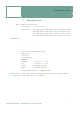
Chapter 1 Identification 1 Model Identification RFID Reader UF70 Certum Serial number 00 – 0001 – UF70 Part number TUG-E1ML-4O00-F4-00E1 ETSI version, protection class IP40 TFG-E1ML-4O00-F4-00E1 FCC version, protection class IP40 TUG-E1ML-4O00-R4-00E1 ETSI version, protection class IP65 TFG-E1ML-4O00-R4-00E1 FCC version, protection class IP65 Manufacturer Brooks Automation (Germany) GmbH RFID Division Gartenstr.
Chapter 1 Identification Designated use This product is exclusively developed for reading and writing of passive UHF transponders (e.g. EPC Class1 Gen2). Any other use of this device constitutes misuse and renders the user's authority to install and operate the device invalid. This product is designed to be mounted and operated in an industrial setting as a built-in-device only.
Chapter 2 Safety Instructions 2 Safety Instructions This chapter gives you an overview of the following topics: ■ Area of application and symbols ■ ESD instructions ■ Residual risks ■ Additional instructions 2.1 DANGER Area of application and symbols Danger to life, risk of injuries or damage to property Risks exist when disregarding the installation guide and the safety instructions therein. Carefully read the installation guide before initial commissioning.
Chapter 2 Safety Instructions 2.1.2 Warning symbols Warning against Warning against hazardous area hazardous electrical voltage Warning against Warning against electromagnetic flammable materials radiation Warning against Warning against potentially explosive electrostatically atmosphere sensitive components 2.1.3 Prohibition symbols Unauthorized access is Fire, open flame and prohibited smoking is prohibited Switching is prohibited Prohibition 2.1.
Chapter 2 Safety Instructions 2.2 CAUTION ESD instructions Static electricity can damage electronic components in the device. All persons installing the device must be trained in ESD protection. ESD protective measures must be applied when opening the device. Disconnect the power supply prior to removing or adding components.
Chapter 2 Safety Instructions 2.4 Additional instructions ■ Read and understand all safety instructions prior to installing the device. ■ This documentation was written for specifically trained personnel. The installation may only be carried out by specifically trained personnel. ■ Observe all warnings. Follow all warnings on and in the device and in the documentation. ■ Install the device only in accordance with the manufacturer's instructions.
Chapter 3 Product Specifications 3 Product Specifications This chapter gives you an overview of the following topics: ■ Images ■ Description of the components ■ Technical data 3.1 Images 3.1.
Chapter 3 Product Specifications 3.1.
Chapter 3 Product Specifications 3.1.
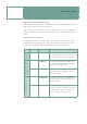
Chapter 3 Product Specifications 3.2 Description of the components Component Description Power LED If the correct voltage is applied to the device, the Power LED is green and the device is operational. Reset button Pressing this button initiates a power-reset of the device. The reset button must be pressed for at least three seconds until all the LEDs of the foil keypad simultaneously start and the hardware reset is executed.
Chapter 3 Product Specifications Component Description I/O ports 1 to 4 A digital input and output can be connected to each antenna port. A 3 wire sensor or dry contact is possible as the input. The output can operate a LED without a series resistor or directly switch 5 V DC (Imax = 100 mA). RS232 interface Communications with the device can be made via the serial interface (9 pin sub-D socket). Baudrates of 1,200 Bd up to 57,600 Bd are possible.
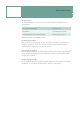
Chapter 3 Product Specifications 3.3 Technical data Technical data Voltage 24 V DC ± 10% Power consumption approx. 0.8 A at 24 V Operating temperature -20 °C to 50 °C -4 °F to 122 °F Storage temperature -40 °C to 85 °C -40 °F to 185 °F Permissible humidity at 50 °C / 122 °F 25 – 85% Protection class IP 40 (optional IP 65) Housing material Passivated aluminum Weight approx.
Chapter 3 Product Specifications 3.3.1 Device label The device label with the CE mark and part/serial number is on the device housing.
Chapter 4 Installation 4 Installation This chapter gives you an overview of the following topics: ■ Safety instructions ■ Qualified installation personnel ■ Unpacking ■ Assembly of the device ■ Antenna installation ■ Power supply ■ Terminal connection ■ External input and output (optional) ■ Commissioning Follow the instructions in the safety chapter Follow the general safety instructions in the chapter Safety Instructions. 4.
Chapter 4 Installation CAUTION Never expose the device to extreme temperature fluctuations, since otherwise condensation develops in the device and causes damage. Do not install the device in the vicinity of voltage lines or other power lines with which they could collide (for example, when drilling), which could result in serious injuries or even death.
Chapter 4 Installation ATTENTION When determining the installation site, keep in mind the length of the antenna wire and the read/write range of the antenna used. 4.2 CAUTION Qualified installation personnel Installation is to be carried out by specially trained personnel only. If you are uncertain about their qualification, contact the manufacturer. CAUTION Installing the device without special training can result in damage to the reader and/or connected devices. 4.
Chapter 4 Installation 4.4 ATTENTION Assembly of the device The mounting surface must be stable, non-flammable, dry and clean. If necessary, clean it before installing the device. The device must be installed so that air can freely circulate vertically through the heat sink, and the operating and environmental conditions specified under Technical data are met at all times.
Chapter 4 Installation 4.5 ATTENTION Antenna installation Consider the required read and write ranges when installing the antenna. The reader can only be used properly if the transponder is located within the individual reading/writing range of the respective antenna. If the transponder is very close to the antenna, the transponder may be detuned by the metal of the antenna and a reading/writing is not possible. We recommend keeping a minimum distance between transponder and antenna of about 10 mm. 4.
Chapter 4 Installation 4.7 Terminal connection The serial interface is a Sub-D socket (9-pin). A normal RS232 extension cable can be used.
Chapter 4 Installation 4.8 External input and output (optional) The following I/O versions are possible: A digital input and output can be connected to each antenna port. A 3 wire sensor or dry contact is possible as the input. The output can operate a LED without a series resistor or directly switch 5 V DC. 4.9 Commissioning 4.9.1 Required operating conditions To operate the reader, the following requirements must be met: An antenna must be connected correctly to the reader.
Chapter 4 Installation 4.9.3 Parameters of the Ethernet interface The Ethernet is connected via an Ethernet module. Tools are available that allow the Ethernet settings to be configured. By using Discovery Tools, all Ethernet devices located in the network can be found. The respective device can be configured via a web server and a web browser via a double click. If the TCP / IP address is known, the web server can also be directly opened in a browser also follows: http://xxx.xxx.xxx.
Chapter 4 Installation Configuration IMPORTANT The "Factory Default Settings" must not be set under any circumstances as they are not the factory settings of Brooks. Any other settings of the Ethernet device (exept the IP address) must not be changed. Otherwise a fault-free communication cannot be guaranteed by Brooks. Digi Device Discovery The tool displays all devices that have a Digi Connect ME. Devices that are not in the same subnet are also displayed.
Chapter 4 Installation Selection window Input window Installation Guide - RFID Reader UF70 Certum 29
Chapter 5 Service and Troubleshooting 5 Service and Troubleshooting This chapter gives you an overview of the following topics: ■ Customer service ■ Troubleshooting 5.1 Customer service Brooks Automation (Germany) GmbH RFID Division Gartenstr. 19 95490 Mistelgau GERMANY Telephone +49 (0) 9279 - 991 550 Fax +49 (0) 9279 - 991 501 E-mail rfid.support@brooks.
Chapter 5 Service and Troubleshooting 5.2 Troubleshooting Follow the instructions specified in the safety chapter Follow the general safety instructions in the chapter Safety Instructions. The transponder reader and its components must be serviced by the manufacturer only! If errors occur, follow the instructions in the Product Manual of the RFID Reader UF70 Certum. If you are uncertain about errors and their handling, contact the manufacturer, see Customer service.
Chapter 6 Dismantling and Disposal 6 Dismantling and Disposal This chapter gives you an overview of the following topics: ■ Dismantling ■ Disposal 6.1 Dismantling Remove the power supply! Remove all cables! Loosen and remove the mounting screws! Remove the device from the installation area! 6.2 Disposal The device and its components are made of various materials. Dispose of these materials separately, and observing the legal regulations of your country.
Index A Assembly 23 C Commissioning 26 D Declaration of conformity 7 Device label 19 E Ethernet settings 27 H Humidity 20 I Installation dimensions 23 M Malfunctions 24 P Power supply 24 Prohibition symbols 10 R Relative humidity 20 S Safety Instructions 9 Safety instructions 20 Safety symbols 9 Serial number 19 Sub-D Socket 25 T Temperature 20 W Warning symbols 10