
Manual


2-3
Models 1350E and 1355E
Section 2 Installation
Installation and Operation Manual
X-VA-1350E-eng
Part Number: 541B082AAG
August, 2012
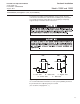
Figure 2-1 Typical Flowmeter Installation
A - Inlet Valve B - Outlet Valve C - Bypass Valve
D - Control Valve E - Drain Valve
HORIZONTAL
LINE
DA
E
C
VERTICAL
LINE
B
B
A
E
FLOWMETER
C
D
FLOWMETER
It is recommended that a final leak test of the system plumbing and meter
be performed before subjecting it to process fluid.
(See Section 4, Paragraph 4-2, e.)
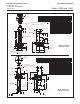
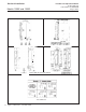
2-5 Installation (See Figures 2-1, 2-2, 2-3, 2-4 and 2-5)
The flowmeter should be mounted within 6° of true vertical. The inlet
connection to the flowmeter is in the bottom end fitting. The connections
are normally horizontal, female NPT. Be sure the piping is adequately
supported to prevent undue strain on the meter.