
Owner manual

4-8
Brooks
®
Model 5851E
Section 4 Maintenance
Installation and Operation Manual
X-TMF-5851E-MFC-eng
Part Number: 541B104AAG
November, 2008
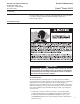
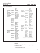
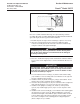
9. Install the coil assembly (2) over the valve stem assembly (6) and
secure with jam nut (1).
10.Install the printed circuit (PC) board (15), secure with the bracket (24)
and two screws. Plug the connector from the sensor assembly onto the
PC Board. The flow arrow on the connector should be pointing toward
the valve assembly.
11.Install the electronics cover (23) on the controller, secure with three
screws (20). Plug the connector from the valve coil into the PC Board
through the hole in electronics cover.
12.Prior to installation leak and pressure test to any applicable pressure
vessel codes.
C. ADJUSTING THE CONTROL VALVE
The Model 5851E control valve has been factory adjusted to insure proper
operation. Readjustment is only required if any of the following parts have
been replaced:
Orifice (12)
valve stem (6)
plunger (7)
lower guide springs (8)
valve seat (11)
The valve is adjusted in Brooks mass flow controllers by adding spacers (9
and 10) to the control valve assembly to vary the air gap and initial preload.
Spacers are used to affect the proper adjustment because they provide a
reliable and repeatable means for adjustment. Screw type adjustment
mechanisms can change with pressure or vibration and introduce an
additional dynamic seal that is a potential leak site and source for
contamination. Refer to Figure 4-2 for spacer locations.
The preload determines the initial force that is required to raise the valve
seat off the orifice and start gas flow. If the preload is insufficient the valve
will not fully close and gas will leak through. If the preload is excessive the
magnetic force generated between the plunger and stem will be insufficient
to raise the plunger and the valve will not open.
The airgap is the space between the top of the plunger and stem. The
airgap determines the force between the plunger and stem at a given
voltage and the total travel of the valve. If the airgap is too small the
plunger travel may be insufficient to fully open the valve, also the magnetic
force may be too high for a given valve coil voltage. If the airgap is too
large the magnetic force will be insufficient to raise the plunger and the
valve will not open.
Note: Prior to starting the valve adjustment procedure check to insure that
the orifice is properly seated and that the valve parts are not bent or
damaged.
1. Adjustment Procedure (Refer to Section 5, Spare Parts for spacer kit)
a. Remove the electronics cover (23) from the controller. Insure that
the connector from the coil assembly (2) is properly reconnected to
the PC Board after the electronics cover is removed.
b. Perform the electrical and gas connections to the controller following
the instructions in Section 2 of this manual. Use a clean dry inert
gas, such as nitrogen for this procedure. Do not apply gas pressure
to the controller at this time.
c. Disassemble the control valve following the procedure given in