
Manual


14
Installation and Operation Manual
X-TMF-FM-MFC-eng
PN 541-C-007-AAG
April, 2008
Flomega, Liquid MFC’s/MFM’s
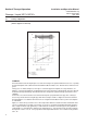
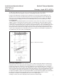
e. Accurate upstream pressure regulation is required to ensure proper valve control operation.
Piping should be sized to avoid excessive pressure drops. It is recommended to install the controller in
a vertical-upwards position. This installation position will release the entrained gas in the valve
compartment more easily. A constant higher back pressure than atmospheric pressure is also
beneficial for the stability of the control valve performance.
2-12 Installation
The Brooks (electrical/electronic) equipment bearing the CE mark has been succesfully tested to the
regulations of the Electro Magnetic Compatability (EMC directive 89/336/EEC). Special attention however
is required when selecting the signal cable to be used with CE marked equipment.
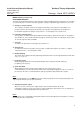
Quality of the signal cable and cable connectors:
• Brooks standard supplies high quality cable(s) which meets the specifications for CE certification.
• If you provide your own signal cable you should use a cable which is overall completely screened with
at least 100% shield.
Cable connectors used should be made from metal and cable glands should either be metal or metal
shielded.
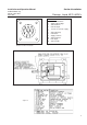
The cable screen should be connected to the metal connector or gland and shielded at both ends over
360 degrees. For pin configuration, please refer to fig. 2-1 and 2-2 or 2-3 and 2-4.
The cable entry device for the Ex Proof execution, shall be in type of explosion protection flameproof
enclosure “d”, suitable for the conditions of use and correctly installed. The minimum ingress protection
requirement of IP 6X according to EN 60529 must be satisfied.
Cables suitable for a temperature of at least 90°C shall be used.
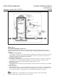
Recommended installation procedures:
a. The flow controller or sensor should be inspected for cleanliness or any visible external
damage after it is removed from its shipping container.
b. The FLOMEGA should be located in an atmosphere with vibration levels lower than SAMA
PMC 31.1 condition 3.
c. Leave sufficient room for access to the electrical components.
d. Install in such a manner that it permits easy removal if the instrument requires cleaning.
CAUTION
When installing the controller, care should be taken that no foreign
materials enter the inlet or outlet of the instrument.
CAUTION
The models 5881/5892 can be installed in any position. However,
mounting orientations other than original factory calibration position
(mounting holes down) may require re-zeroing to regain the specified
accuracy.
Section 2 Installation