
Manual


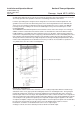

17
Installation and Operation Manual
X-TMF-FM-MFC-eng
PN 541-C-007-AAG
April, 2008
Flomega, Liquid MFC’s/MFM’s
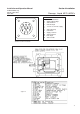
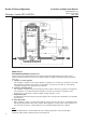
As with relative high flows more heat-current is involved, the thermal “lag”of the fluidum increases. Also the
decreasing operation of the guideline reduces the outstanding performance of the device.
For flows up to 1000 g/h, the design has been changed to overcome above mentioned problems. The
guideline is left out to reduce the thermal lag effects. Since the heat-gradient now varies with flow, two
extra sensors (T5 and T6) are added to measure the heat-gradient at T1, T2 (see figure 3-2). With this
technique, flows up to 1000 g/h can be measured with high accuracy. This new technique is used in
models 5882/5892.
The FLOMEGA model 5881/82 liquid mass flow controller consists of the same unique sensor design. In
addition, an in-line control valve and control electronics are included. This control valve differs from the
traditional Brooks series 5850 mass flow controllers for gases. In the latter, expansion of the flow in the
control valve compartment may lead to outgassing of the fluid and influences the controllability of the mass
flow controller easily. A manual degassing of the valve would be required. Therefore, Brooks Instrument
developed an in-line control valve especially designed for accurately controlling the liquid flowrates. Dead
volumes in the flow path have been eliminated as much as possible to ensure troublefree operation. For
easy maintenance, the valve orifice is field adjustable.
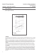
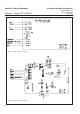
Electronics (see figure 3-3)
There are two control sections in the electronics, one for creating a temperature difference between top
and bottom of the sensor (upper part of block diagram) and one for controlling the valve. The signal gene
rated by the temperature elements T1 and T2 are amplified in such a way that 100% of the customer’s
flowrate equals 100% full scale output. This amplification has a three switch selectable coarse adjustment
and one potentiometer for fine tuning. Using the temperature difference of T5 and T6 (5882/92) the output is
corrected by the heat-gradient. For rapid response output this amplified signal is applied to a “D” action.
A comparison amplifier compares the output signal with the customer adjusted setpoint value and will drive
the valve to the desired value via a P.I.D. action. For specific fluidum which requires a one time
linearisation, a network is created that linearises the sensor’s output signal.
A voltage to current converter is added to provide a 0-20 mA or 4-20 mA output.
Figure 3-2 Measurement Principle
Section 3 Theory of Operation