
Manual


24
Installation and Operation Manual
X-TMF-FM-MFC-eng
PN 541-C-007-AAG
April, 2008
Flomega, Liquid MFC’s/MFM’s
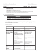
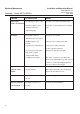
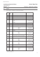
SYMPTOM POSSIBLE CAUSE REMEDY
Output signal 4a) VOR input at +5V to +15V Determine cause of this undesirable input
remains at maximum
4b) Flow too high because Clean orifice or valve. Adjust orifice according
of leakage of the valve to 6a
(valve voltage min)
Oscillation 5a) Unstable upstream/ Check pressure regulator
downstream pressure control
5b) Differential pressure Power pressure or change prop. gain
too high
5c) Gas is valve compartment Purge system: VOR+ (2 minutes)
or 100% setpoint (15 minutes)
5d) Very low viscosity and/or Change prop. gain. Decrease gain
high density of liquid
(compared with water)
5e) Outgassing of liquid Max. temp. of liquid close to boiling point.
Choose proper liquid delivery system. Vertical
position is recommended. Apply higher back
pressure, proper pressurising gas
Low flow at zero 6a) Valve leakage Adjust orifice (turn C.W.), valve should open
setpoint at 5V-7Vdc (1 bar diff. pressure)
Output is fluctuating 7a) Pulsation because Apply damping (potmeter P8)
of pump
Output is stable but 8a) VOR+ has been used Shut valve and wait 20 minutes
flow is too high too long
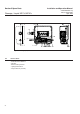
Section 4 Maintenance