Installation and Operation Manual X-PD-BM-Ovals-eng Part Number: 541B031AAG January, 2009 BM Oval Series Brooks® Oval Flowmeters, BM Oval Series, Models BM04 Through BM50
BM Oval Series Installation and Operation Manual X-PD-BM-Ovals-eng Part Number: 541B031AAG January, 2009 Essential Instructions Read this page before proceeding! Brooks Instrument designs, manufactures and tests its products to meet many national and international standards. Because these instruments are sophisticated technical products, you must properly install, use and maintain them to ensure they continue to operate within their normal specifications.
Installation and Operation Manual X-PD-BM-Ovals-eng Part Number: 541B031AAG January, 2009 BM Oval Series Dear Customer, We appreciate this opportunity to service your flow measurement and control requirements with a Brooks Instrument device. Every day, flow customers all over the world turn to Brooks Instrument for solutions to their gas and liquid low-flow applications.
Installation and Operation Manual X-PD-BM-Ovals-eng Part Number: 541B031AAG January, 2009 BM Oval Series THIS PAGE WAS INTENTIONALLY LEFT BLANK
Installation and Operation Manual X-PD-BM-Ovals-eng Part Number: 541B031AAG January, 2009 Contents BM Oval Series Paragraph Page Number Number Section 1 Introduction 1-1 Purpose .................................................................................................................................................... 1-1 1-2 Description ................................................................................................................................................
Contents BM Oval Series Installation and Operation Manual X-PD-BM-Ovals-eng Part Number: 541B031AAG January, 2009 Figures Figure Page Number Number 1-1 Dimensions............................................................................................................................................ 1-4 1-2 Standard LCD Display ........................................................................................................................... 1-5 1-3 Deluxe LCD Display ..........................
Installation and Operation Manual X-PD-BM-Ovals-eng Part Number: 541B031AAG January, 2009 Contents BM Oval Series Tables Table Page Number Number 1-1 Capacities .............................................................................................................................................. 1-1 1-2 Maximum Working Pressures and Temperatures ................................................................................. 1-2 1-3 K-Factors ......................................................
Contents Installation and Operation Manual X-PD-BM-Ovals-eng Part Number: 541B031AAG January, 2009 BM Oval Series THIS PAGE WAS INTENTIONALLY LEFT BLANK iv
Section 1 Introduction Installation and Operation Manual X-PD-BM-Ovals-eng Part Number: 541B031AAG January, 2009 BM Oval Series 1-1 Purpose The Brooks® BM Series Flowmeters, hereafter called flowmeters, are positive displacement meters that measure extremely low flows of clean liquid with high accuracy. The flowmeter generates an electrical signal proportional to flow for use with a wide variety of electronic instrumentation.
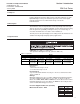
Section 1 Introduction Installation and Operation Manual X-PD-BM-Ovals-eng Part Number: 541B031AAG January, 2009 BM Oval Series Table 1-2 Maximum Working Pressures and Temperatures Materials Body Rotors(Gears) Aluminum, Screwed Aluminum, Flanged, 150 lb Aluminum, Screwed Aluminum, Flanged, 150 lb. 316SS, Screwed 316SS, Flanged, 150 lb. 316SS, Screwed 316SS, Flanged, 150 lb.
Section 1 Introduction Installation and Operation Manual X-PD-BM-Ovals-eng Part Number: 541B031AAG January, 2009 BM Oval Series (Refer to Table 1-3, below) Nominal K-Factor for both Reed and Hall effect switch: Table 1-3 K-Factors Model BM04 BM07 BM10 BM40 BM50 K-Factors/Pulse Output Resolution Gallons Liters Single Switch Dual Switch Single Switch Dual Switch 424.3 197 136.3 54.9 25.29 848.6 394 272.6 109.8 50.58 112 52 36 14.5 6.68 224 104 72 29 13.
Section 1 Introduction BM Oval Series Figure 1-1 Dimensions 1-4 Installation and Operation Manual X-PD-BM-Ovals-eng Part Number: 541B031AAG January, 2009
Section 1 Introduction Installation and Operation Manual X-PD-BM-Ovals-eng Part Number: 541B031AAG January, 2009 BM Oval Series 1-4 Display Options Standard LCD Display The standard liquid crystal (LC) display is available on the BM04,BM07, BM10, BM40 and BM50 models. Features: • Seven (7) digit x 11/16" (17 mm) Liquid Crystal Display • Rotatable in 900 increments. • Selectable flow rate display in U.S.
Section 1 Introduction Installation and Operation Manual X-PD-BM-Ovals-eng Part Number: 541B031AAG January, 2009 BM Oval Series Deluxe LCD Display The deluxe liquid crystal (LC) display is available on the models BM04, BM07,BM10, BM40 and BM50 models. Features: • Seven (7) digit x 1/2" (12.7 mm) Liquid Crystal Display • Rotatable in 90° increments • Selectable flow rate display in U.S. Gallons or Liters (according to model selected) • 2 total displays - resettable and non-resettable, up to 999999.
Section 1 Introduction Installation and Operation Manual X-PD-BM-Ovals-eng Part Number: 541B031AAG January, 2009 BM Oval Series Mechanical Display The mechanical display is available on the BM04, BM10, BM40 and BM50 models. Features: • U.S. Gallons or Liters • 2 total displays 1 to 9,999 liters or 1/10 to 999.9 U.S. Gallons (resettable) 1 to 999;999 Liters (X10) or 1 to 999,999 U.S.
Section 1 Introduction Installation and Operation Manual X-PD-BM-Ovals-eng Part Number: 541B031AAG January, 2009 BM Oval Series 1-5 Accessories and Options (Refer to Table 1-7) • Standard LCD Display • High Viscosity Rotors (gears) • Deluxe LCD Display • High Temperature Rotors (gears) • Mechanical Register • Heating Jacket • Recommended Strainer Sizes, (Refer to table 1-6) Table 1-6 Recommended Strainer Sizes Strainer Recommendations Model Max Partical Size BM04 0.011" (0.28mm) BM07 0.011" (0.
Section 1 Introduction Installation and Operation Manual X-PD-BM-Ovals-eng Part Number: 541B031AAG January, 2009 BM Oval Series Table 1-9 Model Codes MODEL BASIC MODEL BM BROOKS-OVAL CODE NOMINAL SIZE 04 1/2 INCH 07 1 INCH 10 1 INCH 40 1/12 INCH 50 2 INCH CODE REVISION A CURRENT REVISION CODE BODY MATERIAL A ALUMINUM B BRONZE (BM10 METER ONLY) R PPS (BM7 METER ONLY) S 316 STAINLESS STEEL CODE ROTOR/GEAR MATERIAL R PPS ROTOR (GEAR) SET S 316 STAINLESS STEEL ROTOR (GEAR) SET CODE PULSER/DISPLAY P PULSE OUT
Section 1 Introduction Installation and Operation Manual X-PD-BM-Ovals-eng Part Number: 541B031AAG January, 2009 BM Oval Series THIS PAGE WAS INTENTIONALLY LEFT BLANK 1-10
Section 2 Installation Installation and Operation Manual X-PD-BM-Ovals-eng Part Number: 541B031AAG January, 2009 BM Oval Series Installation 2-1 General This section contains the procedures for the receipt and installation of the flowmeter. Do not attempt to start the system until the flowmeter has been permanently installed. It is extremely important that the start-up procedures be followed in the exact sequence presented.
Section 2 Installation Installation and Operation Manual X-PD-BM-Ovals-eng Part Number: 541B031AAG January, 2009 BM Oval Series 2-4 Return Shipment Prior to returning any instrument to the factory visit the Brooks website www.BrooksInstrument.com for a Return Materials Authorization Number (RMA#), or contact one of the following locations: Brooks Instrument 407 W. Vine Street P.O.
Section 2 Installation Installation and Operation Manual X-PD-BM-Ovals-eng Part Number: 541B031AAG January, 2009 BM Oval Series 2-6 Installation To provide for optimum system performances the following guidelines should be observed: 1. Before use, confirm the fluid to be used is compatible with the meter. 2. The flowmeter must be installed so the shafts of the rotors are horizontal, never vertical or “on end”. Severe damage to components may be the result, (See Figure 2-1). 3.
Section 2 Installation BM Oval Series Figure 2-3 Reed Switch Connections for PCB Terminals Figure 2-4 4-20 mA Loop Powered Transmitter 2-4 Installation and Operation Manual X-PD-BM-Ovals-eng Part Number: 541B031AAG January, 2009
Section 2 Installation Installation and Operation Manual X-PD-BM-Ovals-eng Part Number: 541B031AAG January, 2009 BM Oval Series (Refer to Table 2-1 for strainer size), ( See Figures 2-5 and 2-6). 4. Valves should be installed to facilitate removal of the flowmeter and strainer, (See Figures 2-4 and 2-5). 5. Install the flowmeter on the discharge side of a pump whenever possible. 6. Before installing the flowmeter, wash and clean the inside of the pipeline with compressed air or steam.
Section 2 Installation Installation and Operation Manual X-PD-BM-Ovals-eng Part Number: 541B031AAG January, 2009 BM Oval Series VERTICAL LINE Control Valve Outlet Valve OVAL GEAR FLOWMETER Bypass Valve STRAINER Inlet Valve Drain Valve Figures 2-6 Vertical Installation.
Section 3 Operation Installation and Operation Manual X-PD-BM-Ovals-eng Part Number: 541B031AAG January, 2009 BM Oval Series 3-1 General The flowmeter has been completely assembled, checked and calibrated at the factory. Therefore, no adjustments are required for installation. 3-2 Flowmeter Principle of Operation (See Figure 3-1) 2 B B 1 A A The Oval Flowmeter accurately measures liquid flow by using a slight pressure differential to rotate a pair of oval gears.
Section 3 Operation Installation and Operation Manual X-PD-BM-Ovals-eng Part Number: 541B031AAG January, 2009 BM Oval Series 3-3 Pulse Generator Principle of Operation (See Figure 3-1) Pulse Generator: When fluid passes through the meter, rotors turn. The magnets which are located in the rotors will pass across the pulser circuit board (containing either Reed Switches or Hall Effect sensors).
Section 3 Operation Installation and Operation Manual X-PD-BM-Ovals-eng Part Number: 541B031AAG January, 2009 BM Oval Series 3-5 Operating Precautions Periodic inspections should be made during flowmeter operation. The following points should be checked and the flowmeter shut down if any discrepancy is found. 1. When changing flowrates In applications where the flowrate varies or where shut-off valveopening and closure takes place in batch operation, avoid rapid changes in flowrate across the meter.
Section 3 Operation Installation and Operation Manual X-PD-BM-Ovals-eng Part Number: 541B031AAG January, 2009 BM Oval Series 3. Liquids that readily adhere or gel. Liquids that tend to adhere and solidify or gel at flow velocities around zero must thoroughly be washed away from the meter interior with running cleaning fluid before shutdown. Negligence of this precaution could produce an immovable mass of components when the operator attempts to resume meter operation.
Section 3 Operation Installation and Operation Manual X-PD-BM-Ovals-eng Part Number: 541B031AAG January, 2009 BM Oval Series Brief Description of the Standard Display The Standard display is a microprocessor driven instrument designed to display flowrate, Total and accumulated Total. The Standard Display is designed to be implemented in many types of applications. For that reason, a SETUP-level is available to configure your Standard Display according to your specific requirements.
Section 3 Operation Installation and Operation Manual X-PD-BM-Ovals-eng Part Number: 541B031AAG January, 2009 BM Oval Series Alarm 01 - 03: When Alarm is displayed, please consultSection 4 for Problem solving. Programming Setup-Level: Configuration of the Standard Display is done at SETUP-level. SETUPlevel can be reached by pressing the PROG/ENTER key for 7 seconds; at which time, both arrows will be displayed. In order to return to the operator level, PROG will have to be pressed for three seconds.
Installation and Operation Manual X-PD-BM-Ovals-eng Part Number: 541B031AAG January, 2009 Section 3 Operation BM Oval Series Programming Procedure The Programming procedure (PROG) is applicable for programming, selecting or deleting values on SETUP-level. The procedure is executed as follows: 1) Enter the desired SETUP sublevel as detailed in Section 3.2.1 2) Press PROG briefly, 3) Enter a value or make a selection with the pu keys. 4) Set the operation by pressing ENTER.
Section 3 Operation BM Oval Series 3-8 Installation and Operation Manual X-PD-BM-Ovals-eng Part Number: 541B031AAG January, 2009 Flowrate - 2 The settings for Total and flowrate are entirely separated. In this way, different measurement units can be used like cubic meters for Total and litres for flowrate. FLOWRATE; MEASUREMENT UNIT - SETUP LEVEL 21: Setup - 21 determines the measurement unit for flowrate. The following units can be selected: mL - L - m 3 - mg - g - kg - ton - GAL - bbl - lb.
Section 3 Operation Installation and Operation Manual X-PD-BM-Ovals-eng Part Number: 541B031AAG January, 2009 BM Oval Series Power Management - 4 As the Standard Display is normally battery powered, the user will have the concern of reliable measurement over a long period of time. The Standard Display has several smart power management functions to extend the battery life time significantly.
Section 3 Operation Installation and Operation Manual X-PD-BM-Ovals-eng Part Number: 541B031AAG January, 2009 BM Oval Series OTHERS; SERIAL NUMBER - SETUP LEVEL 63: For support and maintenance it is important to have information about the characteristics of the Standard Display. Your supplier will ask for this information in the case of a serious breakdown or to assess the suitability of your model for upgrade considerations. OTHERS; PASSWORD - SETUP LEVEL 64: All SETUP-values can be password protected.
Section 3 Operation Installation and Operation Manual X-PD-BM-Ovals-eng Part Number: 541B031AAG January, 2009 BM Oval Series Remarks Terminal Connectors: Terminal 1-3; Flowmeter Inputs The pulse has to be connected to terminal 2. The screen of the signal wire must be connected to terminal 3 (GND). The voltage supply (3.2 Vdc) to the flowmeter should be connected to terminal 4. Please read par. 4.2. for power supply flowmeter.
Section 3 Operation BM Oval Series Installation and Operation Manual X-PD-BM-Ovals-eng Part Number: 541B031AAG January, 2009 3-8 Deluxe LCD Display Description Normal Operation The quantity of liquid passing through the meter will be measured and displayed (partial quantity counter). No additional devices are required. Automatic Operation (Presettable Batch Controller) A preset quantity can be transferred in automatic operation.
Section 3 Operation Installation and Operation Manual X-PD-BM-Ovals-eng Part Number: 541B031AAG January, 2009 BM Oval Series Figure 3-7 Batch Control Diagram Table 3-2 Calibration Settings by Model Number 3-13
Section 3 Operation Installation and Operation Manual X-PD-BM-Ovals-eng Part Number: 541B031AAG January, 2009 BM Oval Series 3-9 Deluxe LCD Specifications Figure 3-8 Deluxe LCD The Deluxe Liquid Crystal Display Measuring Unit: Can be set to Liters, US Gallons, or Imperial Gallons. Imperial Gallons = "IMP GAL" = 4.5460 Liters US Gallons = "US GAL" = 3.7854 Liters Calibration Constant: 10 different constants can be recorded. Each constant can be set by keys within the range of 0.0000 to 0.99999.
Section 3 Operation Installation and Operation Manual X-PD-BM-Ovals-eng Part Number: 541B031AAG January, 2009 BM Oval Series 3-10 Deluxe LCD Operation Meter Keys Overview Figure 3-9 Locations and Functions of Meter Keys 3-15
Section 3 Operation Installation and Operation Manual X-PD-BM-Ovals-eng Part Number: 541B031AAG January, 2009 BM Oval Series Figure 3-10 Operation View (Normal Mode) Figure 3-11 Cancel Total Quantity (Normal Mode) Figure 3-12 Display of Flowrate (Normal Mode) Normal Operation Mode: To perform the following procedures in normal operation mode (Refer to Figure 3-10).
Section 3 Operation Installation and Operation Manual X-PD-BM-Ovals-eng Part Number: 541B031AAG January, 2009 BM Oval Series Automatic Operation Mode: Display is flashing; change respective setting by "+";"-" or "1-10". The setting will be confirmed by pressing "ENTER". To perform the following procedures in automatic mode: (Refer to Figure 3-12).
Section 3 Operation BM Oval Series Figure 3-15 Operation View (Automatic Mode) 3-18 Installation and Operation Manual X-PD-BM-Ovals-eng Part Number: 541B031AAG January, 2009
Installation and Operation Manual X-PD-BM-Ovals-eng Part Number: 541B031AAG January, 2009 Section 3 Operation BM Oval Series Table 3-3 Fault Indicator Figure 3-16 Calibration Constant 3-19
Section 3 Operation BM Oval Series Figure 3-17 Select Measuring Unit Figure 3-18 Connections Diagram 3-20 Installation and Operation Manual X-PD-BM-Ovals-eng Part Number: 541B031AAG January, 2009
Section 3 Operation Installation and Operation Manual X-PD-BM-Ovals-eng Part Number: 541B031AAG January, 2009 BM Oval Series Figure 3-19 Amplifier Diagram Example Application: Connections and Diagrams are typical. Actual installations may vary from those shown in this publication. 1. Electronic display mounted on liquid meter; amplifier with 1 output signal for installationinto a switchboard for controlling 1 valve. (Refer to Figure 3-16). Figure 3-20 Example Application #1.
Section 3 Operation Installation and Operation Manual X-PD-BM-Ovals-eng Part Number: 541B031AAG January, 2009 BM Oval Series Necessary Cable Connections; A. Control cable from meter to amplifier. B. Voltage cable from amplifier to meter. Figure 3-21 Example Application #2. 2. Electronic display mounted on liquid meter; amplifier with 1 output signal for installation into a switchboard for controlling 1 valve; external Start/Stop device. (Refer to Figure 3-17). Necessary Cable Connections: A.
Section 3 Operation Installation and Operation Manual X-PD-BM-Ovals-eng Part Number: 541B031AAG January, 2009 BM Oval Series Figure 3-22 Example Application #3. Necessary Cable Connections: A. Pulse cable from LC-Display to quick action tap (Max. 12m). B. Control Cable from quick action tap to amplifier. C. Supply voltage cable from amplifier to valve. Summary Tables: If the battery has not been removed within one minute, all registered constants will be reset to 0500.
Section 3 Operation Installation and Operation Manual X-PD-BM-Ovals-eng Part Number: 541B031AAG January, 2009 BM Oval Series THIS PAGE WAS INTENTIONALLY LEFT BLANK 3-24
Section 4 Maintenance Installation and Operation Manual X-PD-BM-Ovals-eng Part Number: 541B031AAG January, 2009 BM Oval Series 4-1 General No routine maintenance, cleaning or lubrication is required on the flowmeter. The user should establish a schedule for the periodic checking and cleaning of the strainer. Cleaning the strainer depends upon product application and time of use. 4-2 Manufacturer’s Maintenance Recommendations The following items apply to all flowmeters.
Section 4 Maintenance BM Oval Series Installation and Operation Manual X-PD-BM-Ovals-eng Part Number: 541B031AAG January, 2009 4-3 Disassembly - General Before proceeding with any disassembly, follow these steps: 1. Close all valves and isolate the meter from line pressure or back pressure. 2. If used at elevated temperatures, reduce temperature of meter (including internals) to ambient. 3. Disconnect any electrical lines to or from the meter. 3a.
Section 4 Maintenance Installation and Operation Manual X-PD-BM-Ovals-eng Part Number: 541B031AAG January, 2009 BM Oval Series remove the four retaining screws on the display face (item 16). Lift off the display unit and remove the 9 pin connector at the back of the display unit. (Refer to Figure 5-3). 4. (See Figure 5-1) Reduce the pressure inside the meter to zero by draining that section of the line which is isolated along with the meter.
Section 4 Maintenance Installation and Operation Manual X-PD-BM-Ovals-eng Part Number: 541B031AAG January, 2009 BM Oval Series 4-5 Cleaning Clean and inspect all parts removed from the flowmeter assembly. It is recommended to wash all parts thoroughly in a light weight solvent. Dry thoroughly with compressed air and/or lint free wipers. 4-6 Assembly - Flowmeter (Refer to Figure 5-1) It is recommended that new O-rings be installed upon assembly. No lubricant is recommended or required for the O-rings.
Installation and Operation Manual X-PD-BM-Ovals-eng Part Number: 541B031AAG January, 2009 Section 4 Maintenance BM Oval Series 4-7 Battery Replacement 1. Deluxe LCD Display (Refer to Figures 4-2 and 4-3) A.In order to change the battery, you have to remove the electronic display unit from the meter. Replacement of the battery must take place outside of the hazardous area (if applicable). B. Remove the four slotted screws and carefully take off the electronics display unit.
Section 4 Maintenance Installation and Operation Manual X-PD-BM-Ovals-eng Part Number: 541B031AAG January, 2009 BM Oval Series Figure 4-2 Deluxe LCD Display Assembly Parts Figure 4-3 Deluxe LCD Display Assembly Parts 4-8 General Maintenance for the Standard Display • Installation, use, maintenance and de-mounting of this equipment must be carried out by authorised technicians only. • Take good notice of the “Safety rules and precautionary measures” in the front of this manual.
Installation and Operation Manual X-PD-BM-Ovals-eng Part Number: 541B031AAG January, 2009 Section 4 Maintenance BM Oval Series To extend battery life it is advised to disable unused functions. Check periodic: • The condition of the casing and front panel. • The wiring of components for reliability and ageing symptoms. • The process accuracy. As a result of wear and tear, re-calibration of the flowmeter might be necessary. Do re-enter any subsequent K-factors alterations. • The indication for low-battery.
Section 4 Maintenance BM Oval Series Installation and Operation Manual X-PD-BM-Ovals-eng Part Number: 541B031AAG January, 2009 Flowrate: 8mm character-size or 17mm character-size - 5 digits. Settings independent of TOTAL. Measuring units: mL, L, m3, Gallons, KG, ton, lb, bl, cf, rnd, no unit. Time units: second, minute, hour, day. K-factor: 7 positions 0.000010 - 9,999,999. Number of decimals: max. three.
Section 4 Maintenance Installation and Operation Manual X-PD-BM-Ovals-eng Part Number: 541B031AAG January, 2009 BM Oval Series List of DefaultSettings Use this chart to store any changes made to the various SETUP settings: Settings Default Settings Modified: Date: 1.
Section 4 Maintenance BM Oval Series Table 4-1 Troubleshooting 4-10 Installation and Operation Manual X-PD-BM-Ovals-eng Part Number: 541B031AAG January, 2009
Section 5 Parts List Installation and Operation Manual X-PD-BM-Ovals-eng Part Number: 541B031AAG January, 2009 BM Oval Series 5-1 General This section contains the necessary parts required to make up any standard unit that is covered in this instruction manual. Each parts list also contains the recommended spare and replacement parts denoted by an asterisk. For items that are not listed or require additional information, consult the factory.
Section 5 Parts List BM Oval Series Figure 5-1 Exploded Parts Drawing for Model BM04 Pulse Meter 5-2 Installation and Operation Manual X-PD-BM-Ovals-eng Part Number: 541B031AAG January, 2009
Installation and Operation Manual X-PD-BM-Ovals-eng Part Number: 541B031AAG January, 2009 Section 5 Parts List BM Oval Series Figure 5-2 Exploded Parts Drawing for Model BM07 Pulse Meter 5-3
Section 5 Parts List BM Oval Series Figure 5-3 Exploded Display Parts Drawings for Models BM04 and BM07 Pulse Meter 5-4 Installation and Operation Manual X-PD-BM-Ovals-eng Part Number: 541B031AAG January, 2009
Installation and Operation Manual X-PD-BM-Ovals-eng Part Number: 541B031AAG January, 2009 Section 5 Parts List BM Oval Series Figure 5-4 Exploded Parts Drawing for Model BM10 Pulse Meter 5-5
Section 5 Parts List BM Oval Series Figure 5-5 Exploded Parts Drawings for Model BM40 Pulse Meter 5-6 Installation and Operation Manual X-PD-BM-Ovals-eng Part Number: 541B031AAG January, 2009
Installation and Operation Manual X-PD-BM-Ovals-eng Part Number: 541B031AAG January, 2009 Section 5 Parts List BM Oval Series Figure 5-6 Exploded Parts Drawing for Model BM50 Pulse Meter 5-7
Section 5 Parts List BM Oval Series Figure 5-7 Exploded Display Parts Drawings for Models BM10/BM40/BM50 5-8 Installation and Operation Manual X-PD-BM-Ovals-eng Part Number: 541B031AAG January, 2009
Installation and Operation Manual X-PD-BM-Ovals-eng Part Number: 541B031AAG January, 2009 Section 5 Parts List BM Oval Series Figure 5-8 Exploded Parts Drawing - BM10 Mechanical Meter 5-9
Section 5 Parts List BM Oval Series Figure 5-8 BM10 Mechanical Meter (continued) 5-10 Installation and Operation Manual X-PD-BM-Ovals-eng Part Number: 541B031AAG January, 2009
Installation and Operation Manual X-PD-BM-Ovals-eng Part Number: 541B031AAG January, 2009 Section 5 Parts List BM Oval Series Figure 5-9 Exploded Parts Drawing - BM40 Mechanical Meter 5-11
Section 5 Parts List BM Oval Series Figure 5-9 BM40 Mechanical Meter (continued) 5-12 Installation and Operation Manual X-PD-BM-Ovals-eng Part Number: 541B031AAG January, 2009
Installation and Operation Manual X-PD-BM-Ovals-eng Part Number: 541B031AAG January, 2009 Section 5 Parts List BM Oval Series Figure 5-10 Exploded Parts Drawing - BM50 Mechanical Meter 5-13
Section 5 Parts List BM Oval Series Figure 5-10 BM50 Mechanical Meter (continued) 5-14 Installation and Operation Manual X-PD-BM-Ovals-eng Part Number: 541B031AAG January, 2009
Installation and Operation Manual X-PD-BM-Ovals-eng Part Number: 541B031AAG January, 2009 BM Oval Series THIS PAGE WAS INTENTIONALLY LEFT BLANK
Installation and Operation Manual X-PD-BM-Ovals-eng Part Number: 541B031AAG January, 2009 BM Oval Series LIMITED WARRANTY Seller warrants that the Goods manufactured by Seller will be free from defects in materials or workmanship under normal use and service and that the Software will execute the programming instructions provided by Seller until the expiration of the earlier of twelve (12) months from the date of initial installation or eighteen (18) months from the date of shipment by Seller.