Installation and Operation Manual X-VA-GT1000-eng Part Number: 541B078AAG March, 2014 GT1000 Series Brooks® GT1000 Industrial Glass Tube Variable Area Flowmeter Model GT1020 Model GT1024
GT1000 Series Installation and Operation Manual X-VA-GT1000-eng Part Number: 541B078AAG March, 2014
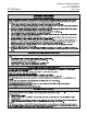
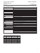
Installation and Operation Manual X-VA-GT1000-eng Part Number: 541B078AAG March, 2014 WARNING GT1000 Series WARNING GLASS TUBE EXPLOSION HAZARD GLASS TUBE EXPLOSION HAZARD Plastic protective sleeve must remain over glass tube. (Meter sizes 7 -13 only) Fasten meter windows securely. Do not operate above pressure and temperature limits. Avoid pressure and flow surges. Do not service or repair while pressurized. Read and understand instruction manual.
GT1000 Series Installation and Operation Manual X-VA-GT1000-eng Part Number: 541B078AAG March, 2014 Dear Customer, We appreciate this opportunity to service your flow measurement and control requirements with a Brooks Instrument device. Every day, flow customers all over the world turn to Brooks Instrument for solutions to their gas and liquid low-flow applications.
Installation and Operation Manual X-VA-GT1000-eng Part Number: 541B078AAG March, 2014 Paragraph Number Contents GT1000 Series Page Number Section 1 Introduction 1-1 Description .......................................................................................................................................... 1-1 1-2 Principle of Operation .......................................................................................................................... 1-1 1-3 Specifications ...............
Contents GT1000 Series Installation and Operation Manual X-VA-GT1000-eng Part Number: 541B078AAG March, 2014 Figures Figure Page Number Number 1-1 Principle of Operation .......................................................................................................................... 1-1 1-2 Cross-Section - GT1000 Flow Tubes with Rib Guides ........................................................................ 1-2 1-3 GT1000 Floats (Descriptions refer to floats used in the same size tube)) ....
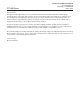
Section 1 Introduction Installation and Operation Manual X-VA-GT1000-eng Part Number: 541B078AAG March, 2014 GT1000 Series 1-1 Description The Brooks® GT1000 combines ruggedness and simplicity in design to provide a versatile glass tube flowmeter suitable for a wide range of applications. The GT1000 O-ring construction minimizes process downtime by allowing for convenient in-line removal of the glass tube for cleaning and maintenance.
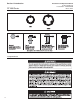
Section 1 Introduction GT1000 Series Figure 1-2 Cross-Section - GT1000 Flow Tubes with Rib Guides Figure 1-3 GT1000 Floats (Descriptions refer to floats used in the same size tube) 1-3 Specifications 1-2 Installation and Operation Manual X-VA-GT1000-eng Part Number: 541B078AAG March, 2014
Installation and Operation Manual X-VA-GT1000-eng Part Number: 541B078AAG March, 2014 Section 1 Introduction GT1000 Series Table 1-1 Specifications - GT1000 Capacities and Pressure Drops See Capacities and Pressure Drop Tables 1-3, 1-4 and 1-5 Flow Accur acy Accuracy Standard: ±2% Full Scale, Class 2.5 acc VDI/VDE Optional: ±1% Full Scale, Class 1.6 acc VDI/VDE Repeatability ≤ 0.
Section 1 Introduction Installation and Operation Manual X-VA-GT1000-eng Part Number: 541B078AAG March, 2014 GT1000 Series Table 1-3 Capacities and Pressure Drop Meter Sizes 2 & 6: Spherical Floats WATER SPHERICAL TUBE Flow Rate AIR* Pressure Drop V. I. C.** Flow Rate Pressure Drop FLOAT cc/min. l/h Inches WC kPa cSt slpm m3/nh Inches WC kPa GLASS 0.42 0.025 0.3 0.08 1.0 0.039 0.0021 0.3 0.08 SIZE 2 SAPPHIRE 0.84 0.05 0.4 0.09 1.0 0.06 0.0033 0.4 0.
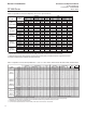
Installation and Operation Manual X-VA-GT1000-eng Part Number: 541B078AAG March, 2014 Section 1 Introduction GT1000 Series Table 1-5 Capacities and Pressure Drop Meter Sizes 2 thru 13: 127mm, 200mm, 250mm Scale, Rib Guided Tubes, Alarm Floats Water Air**** Pressure Drop V. I. C.** Flow Rate Pressure Drop REQ. TUBE FLOAT INCHES W.C. kPa cSt SCFM m3n/h INCHES W.C. kPa psi(*) Size 2 Refer to Capacity Table for Sizes 2 & 6*** Size 6 Refer to Capacity Table for Sizes 2 & 6*** Size 7 R-7M-25-1FT 7-XV-11A 0.
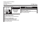
Section 1 Introduction Installation and Operation Manual X-VA-GT1000-eng Part Number: 541B078AAG March, 2014 GT1000 Series 1-4 Optional Equipment - Alarms & Valves GT1000 Alarm Contacts Meter Sizes 7 to 13 The Brooks reed switch alarm is a normally open, latching switch used in conjunction with the GT1000 glass tube flow meter for signaling high and/or low flow or a deviation from a flow setting. A magnet embedded and sealed in the float actuates the alarm switch.
Section 1 Introduction Installation and Operation Manual X-VA-GT1000-eng Part Number: 541B078AAG March, 2014 GT1000 Series Alarm Specifications: Operating Fluid Temperature Limits Reed Switch: Same as meter Inductive: 185°F (85°C) max. Reed Switch Limits - Non-hazardous Locations Maximum Voltage*: 175Vdc, 124Vac Maximum Current*: 250mA Maximum Contact Rating: 3 Watts *(Maximum Switch Specifications) Alarm Hysteresis 8 mm typical (0.
Section 1 Introduction GT1000 Series NPT Connections Flanged Connections Alarm Options 1-8 Figure 1-4 GT1000 Family: NPT, Flanged and w/Alarm Options Installation and Operation Manual X-VA-GT1000-eng Part Number: 541B078AAG March, 2014
Section 1 Introduction Installation and Operation Manual X-VA-GT1000-eng Part Number: 541B078AAG March, 2014 GT1000 Series Inductive Alarms, Alarm Contacts Meter Sizes 2 and 6 Inductive coils for high and/or low flow alarm may be mounted to the instrument to create a highly sensitive, stable and accurate device for signaling high or low flows or deviations from a controlled flow. The inductive alarm can only be used in combination with 316 SS or Carboloy® ball floats.
Section 1 Introduction GT1000 Series Figure 1-5 Alarm Switch(es) for GT1000 Sizes 7 - 13 1-10 Installation and Operation Manual X-VA-GT1000-eng Part Number: 541B078AAG March, 2014
Installation and Operation Manual X-VA-GT1000-eng Part Number: 541B078AAG March, 2014 Section 1 Introduction GT1000 Series Figure 1-6 Dimensions and Specs, Intrinsically Safe Switch Isolators.
Section 1 Introduction GT1000 Series Installation and Operation Manual X-VA-GT1000-eng Part Number: 541B078AAG March, 2014 981Y024 Rev A Figure 1-7 Alarm Wiring Diagram, Reed Switch & Inductive Alarm with Agency Approved Power Supply/Relay Isolator and 1-12 Alarm Wiring Diagram, Reed Switch with Customer Supplied Barrier
Section 2 Installation Installation and Operation Manual X-VA-GT1000-eng Part Number: 541B078AAG March, 2014 Model GT1000 Series 2-1 General This section contains the procedures for the receipt and installation of the instrument. Do not attempt to start the system until the instrument has been permanently installed. It is extremely important that the start-up procedures be followed in the exact sequence presented.
Section 2 Installation Installation and Operation Manual X-VA-GT1000-eng Part Number: 541B078AAG March, 2014 Model GT1000 Series 2-4 Return Shipment Prior to returning any instrument to the factory visit the Brooks website www.BrooksInstrument for a Return Materials Authorization Number (RMA#), or contact one of the following locations: Brooks Instrument 407 W. Vine Street P.O.
Section 2 Installation Installation and Operation Manual X-VA-GT1000-eng Part Number: 541B078AAG March, 2014 Model GT1000 Series VERTICAL LINE HORIZONTAL LINE D FLOWMETER B FLOWMETER B A C D A E E C A - Inlet Valve B - Outlet Valve D - Control Valve C - Bypass Valve E - Drain Valve Figure 2-1 Typical Flowmeter Piping Configuration B. Piping Arrangement It is strongly recommended that the typical piping arrangement shown in Figure 2-1, be used when installing the meter.
Section 2 Installation Installation and Operation Manual X-VA-GT1000-eng Part Number: 541B078AAG March, 2014 Model GT1000 Series THIS PAGE WAS INTENTIONALLY LEFT BLANK 2-4
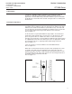
Installation and Operation Manual X-VA-GT1000-eng Part Number: 541B078AAG March, 2014 Section 3 Operation Model GT1000 Series 3-1 Pre-Operational Check Prior to initial start-up and each time the flowmeter is reassembled, the scale alignment should be checked. If the reference line on the tube is aligned with the reference line on the scale, the flowmeter is ready for operation. If the reference lines are not aligned, loosen the screws securing the scale and move it until the marks are in alignment.
Section 3 Operation Installation and Operation Manual X-VA-GT1000-eng Part Number: 541B078AAG March, 2014 Model GT1000 Series To initiate flow through a flowmeter using bypass piping, refer to Figure 3-1. 1. Close flowmeter inlet valve (A) and outlet valve(B). 2. Fully open bypass valve (C) and slightly open control valve (D). 3. Initiate process flow. When flow has stabilized, fully open outlet valve (B), then slowly open inlet valve (A) . 4. Close bypass valve (C). 5.
Installation and Operation Manual X-VA-GT1000-eng Part Number: 541B078AAG March, 2014 Section 4 Maintenance Model GT1000 Series 4-1 Overview 4-1
Section 4 Maintenance Model GT1000 Series Installation and Operation Manual X-VA-GT1000-eng Part Number: 541B078AAG March, 2014 4-2 Cleaning The following procedure may be used for cleaning the tube, float and end fittings. 1. Remove the four screws securing the front window to the meter, then remove the front shield. 2. Slide out the plastic tube retainer holding the tube in position. Do not remove the two screws securing it. 3.
Section 5 Parts Assembly Installation and Operation Manual X-VA-GT1000-eng Part Number: 541B078AAG March, 2014 Model GT1000 Series 5-1 General See Figures 5-1 through 5-3 and Table 5-1 for parts assembly drawings and parts list. Ref.
Section 5 Parts Assembly Model GT1000 Series Figure 5-2 GT1000, Sizes 7-10 Parts Assembly Drawing 5-2 Installation and Operation Manual X-VA-GT1000-eng Part Number: 541B078AAG March, 2014
Installation and Operation Manual X-VA-GT1000-eng Part Number: 541B078AAG March, 2014 Section 5 Parts Assembly Model GT1000 Series Ref.
Section 5 Parts Assembly Installation and Operation Manual X-VA-GT1000-eng Part Number: 541B078AAG March, 2014 Model GT1000 Series Table 5-1 Parts Assembly Item Identification Item # 1 2 3 4 5 6 7 8 10 11 12 13 14 15 16 17 18 19 20 21 22 25 26 27 28 29 30 35 36 37 38 40 41 50 51 52 53 54 55 56 57 58 59 60 65 85 90 91 92 93 5-4 Description HOUSING TUBE BACKING INLET FTG INSERT OUTLET FTG INSERT O-RING (INSERT TO TUBE) INLET END FITTINGS OUTLET END FITTINGS O-RING (INSERT TO FITTING) END FTG RETAINERS BOL
Installation and Operation Manual Section A - Essential Instructions X-VA-GT1000-eng Part Number: 541B078AAG March, 2014 Model GT1000 Series Bulgarian Ɉɫɧɨɜɧɢ ɢɧɫɬɪɭɤɰɢɢ ɉɪɨɱɟɬɟɬɟ ɩɪɟɞɢ ɪɚɛɨɬɚ! Brooks Instrument ɩɪɨɟɤɬɢɪɚ, ɩɪɨɢɡɜɟɠɞɚ ɢ ɬɟɫɬɜɚ ɩɪɨɞɭɤɬɢɬɟ ɫɢ ɩɨ ɬɚɤɴɜ ɧɚɱɢɧ, ɱɟ ɬɟ ɞɚ ɨɬɝɨɜɚɪɹɬ ɧɚ ɦɧɨɝɨɛɪɨɣɧɢ ɧɚɰɢɨɧɚɥɧɢ ɢ ɦɟɠɞɭɧɚɪɨɞɧɢ ɫɬɚɧɞɚɪɬɢ. Ɍɟɡɢ ɨɛɨɪɭɞɜɚɧɢɹ ɬɪɹɛɜɚ ɩɪɚɜɢɥɧɨ ɞɚ ɫɟ ɢɧɫɬɚɥɢɪɚɬ, ɟɤɫɩɥɨɚɬɢɪɚɬ ɢ ɩɨɞɞɴɪɠɚɬ ɡɚ ɞɚ ɫɟ ɝɚɪɚɧɬɢɪɚ, ɱɟ ɳɟ ɦɨɝɚɬ ɞɚ ɪɚɛɨɬɹɬ ɫɴɨɬɜɟɬɧɨ ɧɚ ɬɟɯɧɢɬɟ ɧɨɪɦɚɥɧɢ ɫɩɟɰɢɮɢɤɚɰɢɢ.
Section A - Essential Instructions Installation and Operation Manual X-VA-GF1000-eng Part Number: 541B078AAG March, 2014 Model GT1000 Series Czech Základní instrukce PĜed instalací si pĜeþtČte následující instrukce! Spoleþnost Brooks Instrument konstruuje, vyrábí a testuje tento produkt tak, aby splnil mnoho národních a mezinárodních standardĤ. PĜístroje musí být ĜádnČ nainstalovány, používány a udržovány tak, aby byl zajištČn jejich nepĜetržitý provoz v rámci normálních technických specifikací.
Installation and Operation Manual Section A - Essential Instructions X-VA-GT1000-eng Part Number: 541B078AAG March, 2014 Model GT1000 Series Dansk Grundlæggende vejledninger Læs disse før anvendelse! Brooks Instruments designer, fremstiller og afprøver sine produkter således, at de tilpasser sig både de indenrigs og internationale standarder. Disse udstyr bør installeres, bruges og repareres omhyggeligt, så at de kan virke tilsvarende deres normale anvendelsesperiode.
Section A - Essential Instructions Installation and Operation Manual X-VA-GF1000-eng Part Number: 541B078AAG March, 2014 Model GT1000 Series Dutch Essentiële instructies Lees ze voordat u verder gaat! Brooks Instrument ontwerpt, produceert en test haar producten zodanig dat ze voldoen aan vele nationale en internationale normen. Deze producten moeten correct worden geïnstalleerd, bediend en onderhouden zodat ze binnen hun normale specificaties blijven werken.
Section A - Essential Instructions Installation and Operation Manual X-VA-GT1000-eng Part Number: 541B078AAG March, 2014 Model GT1000 Series Estonian Olulised juhised Enne kasutamist lugege hoolikalt läbi! Brooks Instrument konstrueerib, valmistab ja katsetab oma tooteid selliselt, et need vastaksid paljude erinevate riiklike ja rahvusvaheliste standardite nõuetele. Ainult nõuetekohane paigaldamine, kasutamine ja hooldamine tagab toodete katkematu talitluse tavaspetsifikatsiooni raames.
Section A - Essential Instructions Installation and Operation Manual X-VA-GF1000-eng Part Number: 541B078AAG March, 2014 Model GT1000 Series Finnish Perusohjeet Lue ensin ohjeet huolellisesti! Brooks Instrument suunnittelee, valmistaa ja testaa laitteensa vastaamaan useimpien kotimaisten ja kansainvälisten standardien vaatimuksia. Tuotteet tulee asentaa, käyttää ja huoltaa käyttöohjeiden mukaan jotta niiden toimivuus taataan.
Installation and Operation Manual Section A - Essential Instructions X-VA-GT1000-eng Part Number: 541B078AAG March, 2014 Model GT1000 Series French Instructions essentielles A lire avant de commencer ! Brooks Instrument conçoit, fabrique et teste ses produits pour répondre à de nombreuses normes nationales et internationales. Ces produits doivent être correctement installés, utilisés et entretenus pour pouvoir fonctionner dans le cadre de leurs spécifications normales.
Section A - Essential Instructions Installation and Operation Manual X-VA-GF1000-eng Part Number: 541B078AAG March, 2014 Model GT1000 Series German Wichtige Anweisungen Bitte zuerst lesen! Brooks Instrument entwickelt, produziert und testet seine Produkte derart, dass sie viele nationale und internationale Standards erfüllen. Nur bei korrektem Einbau sowie richtiger Bedienung und Wartung dieser Produkte ist ein Betrieb unter Einhaltung der Standardvorgaben sichergestellt.
Installation and Operation Manual Section A - Essential Instructions X-VA-GT1000-eng Part Number: 541B078AAG March, 2014 Model GT1000 Series Greek ǺĮıȚțȑȢ ȠįȘȖȓİȢ ǻȚĮȕȐıIJİ ʌȡȚȞ ıȣȞİȤȓıİIJİ! Ǿ Brooks Instrument ıȤİįȚȐȗİȚ, ʌĮȡȐȖİȚ țĮȚ įȠțȚȝȐȗİȚ IJĮ ʌȡȠȧȩȞIJĮ IJȘȢ ıİ ıȣȝȝȩȡijȦıȘ ȝİ ʌȜȒșȠȢ İșȞȚțȫȞ țĮȚ įȚİșȞȫȞ ʌȡȠIJȪʌȦȞ. Ǿ ıȦıIJȒ İȖțĮIJȐıIJĮıȘ, ȤȡȒıȘ țĮȚ ıȣȞIJȒȡȘıȒ IJȠȣȢ ĮʌȠIJİȜİȓ ĮʌĮȡĮȓIJȘIJȘ ʌȡȠȨʌȩșİıȘ IJȘȢ ȜİȚIJȠȣȡȖȓĮȢ İȞIJȩȢ IJȦȞ țĮȞȠȞȚțȫȞ ȠȡȓȦȞ.
Section A - Essential Instructions Installation and Operation Manual X-VA-GF1000-eng Part Number: 541B078AAG March, 2014 Model GT1000 Series Hungarian AlapvetĘ utasítások ElĘször olvassa el ezeket! A Brooks Instrument olyan módon tervezi, gyártja és teszteli termékeit, hogy azok megfeleljenek számos belföldi és nemzetközi szabványnak. Ezeket a berendezéseket megfelelĘen kell telepíteni, üzemeltetni és karbantartani ahhoz, hogy mindenképpen a normál mĦködési tartományuknak megfelelĘen üzemelhessenek.
Installation and Operation Manual Section A - Essential Instructions X-VA-GT1000-eng Part Number: 541B078AAG March, 2014 Model GT1000 Series Italian Istruzioni fondamentali Leggerle subito! La Brooks Instrument progetta, fabbrica e collauda i propri prodotti in maniera tale che siano conformi ai vari standard nazionali ed internazionali.
Section A - Essential Instructions Installation and Operation Manual X-VA-GF1000-eng Part Number: 541B078AAG March, 2014 Model GT1000 Series Latvian SvarƯga instrukcija Pirms turpinƗt izlasiet! „Brooks Instrument” projektƝ, ražo un pƗrbauda savus ražojumus atbilstoši daudziem nacionƗlajiem un starptautiskajiem standartiem. Lai nodrošinƗtu šo izstrƗdƗjumu turpmƗku darbƯbu atbilstoši noteiktajiem parametriem, tie ir pareizi jƗuzstƗda, jƗlieto un jƗapkopj.
Section A - Essential Instructions Installation and Operation Manual X-VA-GT1000-eng Part Number: 541B078AAG March, 2014 Model GT1000 Series Lithuanian Pagrindinơs instrukcijos Perskaitykite prieš tĊsdami! „Brooks Instrument“ projektuoja, gamina ir išbando savo gaminius, kad jie atitiktǐ Ƴvairius nacionalinius ir tarptautinius standartus. Šie gaminiai turi bnjti tinkamai montuojami, eksploatuojami ir prižinjrimi, kad ir toliau veiktǐ pagal jiems bnjdingus techninius parametrus.
Section A - Essential Instructions Installation and Operation Manual X-VA-GF1000-eng Part Number: 541B078AAG March, 2014 Model GT1000 Series Polish Zalecenia wstĊpne Prosimy przeczytaü przed rozpoczĊciem uĪytkowania! Brooks Instrument projektuje, wytwarza i testuje swoje produkty tak, aby speániaáy wymagania licznych norm krajowych i miĊdzynarodowych. Te produkty muszą byü poprawnie instalowane, obsáugiwane oraz konserwowane, aby zapewniü ich prawidáowe dziaáanie zgodnie ze specyfikacją techniczną.
Installation and Operation Manual Section A - Essential Instructions X-VA-GT1000-eng Part Number: 541B078AAG March, 2014 Model GT1000 Series Portuguese Instruções Básicas Ler antes de proceder! A Brooks Instrument projecta, fabrica e testa os seus produtos de forma a satisfazer numerosas normas nacionais e internacionais. Estes equipamentos devem ser instalados, utilizados e mantidos de forma adequada, e devem funcionar dentro da sua gama de utilização.
Section A - Essential Instructions Installation and Operation Manual X-VA-GF1000-eng Part Number: 541B078AAG March, 2014 Model GT1000 Series Romanian IndicaĠii de referinĠă CitiĠi-le întâi pe acestea! Brooks Instrument îúi proiectează, produce úi testează produsele într-un mod ce respectă un mare număr de standarde autohtone úi internaĠionale. Aceste instalaĠii trebuie amplasate, exploatate úi întreĠinute corespunzător, pentru ca în toate situaĠiile, domeniul lor de lucru să corespundă operării normale.
Installation and Operation Manual Section A - Essential Instructions X-VA-GT1000-eng Part Number: 541B078AAG March, 2014 Model GT1000 Series Slovak Základné príkazy PreþítaĢ pred inštaláciou! Brooks Instrument svoje výrobky projektuje, vyrába a testuje takým spôsobom, aby tieto vyhoveli domácim aj medzinárodným normám. Tieto zariadenia je potrebné predpísaným spôsobom inštalovaĢ, prevádzkovaĢ a udržiavaĢ, na zabezpeþenie ich spoĐahlivej a normálnej prevádzky v celom pracovnom rozsahu.
Section A - Essential Instructions Installation and Operation Manual X-VA-GF1000-eng Part Number: 541B078AAG March, 2014 Model GT1000 Series Slovene Osnovna navodila Najprej preberite jih Brooks Instrument tako konstruira, izdeluje in terstira svoje izdelke, da oni ustrezajo številnim domaþim in mednarodnim standardom. Te naprave se morajo ustrezno instalirati, koristiti in vzdrževati, da vsekakor delajo ustrezno normalnom podroþju funkcioniranja.
Section A - Essential Instructions Installation and Operation Manual X-VA-GT1000-eng Part Number: 541B078AAG March, 2014 Model GT1000 Series Spanish Instrucciones básicas ¡Léalos primero! El Brooks Instrument proyecta, fabrica y prueba sus productos de manera que éstos respondan a numerosas normas nacionales e internacionales. Dichas instalaciones deben ser emplazadas, operadas y mantenidas adecuadamente, para que puedan marchar de todas formas en conformidad con el alcance normal de funcionamiento.
Section A - Essential Instructions Installation and Operation Manual X-VA-GF1000-eng Part Number: 541B078AAG March, 2014 Model GT1000 Series Swedish Väsentliga anvisningar. Läs detta innan du fortsätter ! Brooks Instrument konstruerar, tillverkar och testar sina produkter med syfte att uppfylla alla nationella och internationella standarder. Dessa produkter måste installeras på rätt sätt, handhas och underhållas för att de skall fungera kontinuerligt enligt deras normala specifikation.
Installation and Operation Manual X-VA-GT1000-eng Part Number: 541B078AAG March, 2014 Model GT1000 Series THIS PAGE WAS INTENTIONALLY LEFT BLANK
Model GT1000 Series Installation and Operation Manual X-VA-GT1000-eng Part Number: 541B078AHG March, 2014 LIMITED WARRANTY Seller warrants that the Goods manufactured by Seller will be free from defects in materials or workmanship under normal use and service and that the Software will execute the programming instructions provided by Seller until the expiration of the earlier of twelve (12) months from the date of initial installation or eighteen (18) months from the date of shipment by Seller.