
User guide


1-4
Section 1 Introduction
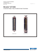
GT1000 Series
Installation and Operation Manual
X-VA-GT1000-eng
Part Number: 541B078AAG
March, 2014
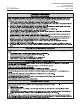
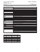
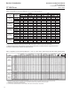
Table 1-4 Capacities and Pressure Drop Meter Sizes 7, 8, 9, 10, 12 &13: 200mm, 250mm Scale, Rib Guided Tubes, Standard Floats
Table 1-3 Capacities and Pressure Drop Meter Sizes 2 & 6: Spherical Floats
*RIARETAW
**.C .I .VetaR wolFLACIREHPS
TUBE FLOAT cc/min. l/h Inches WC kPa cSt slpm m3/nh Inches WC kPa
GLASS 0.42 0.025 0.3 0.08 1.0 0.039 0.0021 0.3 0.08
SIZE 2 SAPPHIRE 0.84 0.05 0.4 0.09 1.0 0.06 0.0033 0.4 0.1
R-2-127-AAAAT 316 SS 1.9 0.11 0.7 0.17 1.0 0.11 0.0066 0.8 0.19
CARBOLOY 3.9 0.23 1.1 0.27 1.0 0.2 0.011 1.2 0.3
GLASS 4.2 0.25 0.3 0.08 1.0 0.3 0.016 0.3 0.08
SIZE 2 SAPPHIRE 8.0 0.48 0.4 0.1 1.0 0.41 0.023 0.4 0.11
R-2-127-DT 316 SS 16 0.98 0.9 0.22 1.0 0.68 0.038 1.0 0.24
CARBOLOY 27 1.6 1.5 0.38 1.0 1.0 0.057 1.7 0.42
GLASS 47 2.8 0.6 0.16 1.0 2.0 0.11 0.7 0.18
SIZE 2 SAPPHIRE 71 4.2 0.8 0.21 1.0 2.7 0.15 0.9 0.23
R-2-127-BT 316 SS 110 7.1 1.8 0.45 1.0 4.1 0.23 2.0 0.51
CARBOLOY 170 10 3.0 0.75 1.0 5.9 0.33 3.3 0.83
GLASS 160 10 1.8 0.45 1.0 7.3 0.4 2.0 0.5
SIZE 6 SAPPHIRE 240 14 2.9 0.72 1.0 9.4 0.52 3.2 0.8
R-6-127-AT 316 SS 410 24 6.1 1.53 1.0 14 0.78 6.8 1.7
CARBOLOY 610 36 10.5 2.61 1.0 19 1.1 11.6 2.9
GLASS 450 27 9.4 2.34 1.0 19 1.0 10.4 2.6
SIZE 6 SAPPHIRE 660 40 14.9 3.7
1.0 24 1.3 16.5 4.1
R-6-127-BT 316 SS 1000 65 30.1 7.5 1.0 35 1.9 33.3 8.3
CARBOLOY 1500 95 57.8 14.4 1.0 49 2.7 64.2 16
Note: 316 SS and Carboloy float capacities listed above can be used to size meters with optional inductance-type alarms
(*) Air flow rates in standard units are at 70'F and 14.7 PSIA, air flow rates in normal units are at 1.013 bar & 20'C
(**) When the viscosity of the fluid exceeds the viscosity immunity ceiling (VIC), a calculated correction is applied to account for
the difference between factory calibration fluid and process fluid.
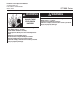
porD erusserPporD erusserP Flow Rate
*****riAretaW
Flow Rate Pressure Drop V. I. C.** Flow Rate Pressure Drop REQ. REQ.
TUBE FLOAT GPM l/h INCHES W.C. kPa cSt SCFM m3n/h INCHES W.C. kPa psi (*) bar(*)
Size 7 GLASS 0.16 36 2.0 0.5 1.0 0.88 1.4 2.0 0.5 0 0
R-7M-25-1FT 316 SS 0.38 86 3.0 0.75 1.0 1.6 2.6 4.0 1 0 0
8-RV-3 0.77 170 3.0 0.75 2.0 3.1 5.0 3.0 0.75 0 0
8-RV-8 1.0 240 5.0 1.3 3.7 4.4 7.0 5.0 1.3 0 0
Size 8 8-RS-8 1.3 310 6.0 1.5 1.8 5.8 9.2 6.0 1.5 0 0
8-8M-25-4FT 8-RS-14 1.8 410 10 2.5 1.9 7.5 11 11 2.8 0 0
8-RV-14 1.4 320 8.0 2 5.4 5.8 9.2 8.0 2 0 0
8-RV-31 2.0 460 16 4 7.0 8.3 13 17 4.3 30 2
8-RS-31 2.5 580 20 5 3.1 10 16 22 5.5 30 2
8-LJ-48 **** 4.8 1100 52 13 1.0 20 33 57 14 30 2
9-RV-33 2.5 570 6.0 1.5 11 10 16 7.0 1.8 0 0
Size 9 9-RS-33 3.2 730 4.0 1 2.4 13 21 8.0 2.0 0 0
R-9M-25-3FT 9-RV-87 3.9 890 14 3.5 17 16 26 16 4.0 30 2
9-RS-87 5.1 1100 18 4.5 3.5 21 35 19 4.8 30 2
10-RV-64 6.2 1400 12 3 15 25 40 14 3.5 0 0
Size 10 10-RS-64 7.8 1700 16 4 3.7 32 50 18 4.5 0 0
R-10M-25-3FT 10-RS-138 1
0 2400 30 7.5 5.5 46 76 36 9 30 2
10-LJ-238 **** 20 4600 104 26 1.0 92 150 16 4 30 2
12-RV-119 13 2900 4.0 1 30 56 88 4.0 1 0 0
Size 12 12-RV-221 17 3900 10 2.5 32 70 110 12 3 0 0
R-12M-20-5FT 12-RV-343 20 4700 16 4 24 86 140 20 5 30 2
12-HF-455 **** 42 9700 30 7.5 10 170 280 32 8 30 2
13-RV-510 31 7200 26 6.5 40 130 200 28 7 0 0
Size 13 13-RS-510 42 9600 36 9 20 170 270 40 10 0 0
R-13M-20-3FT 13-HF-758 **** 62 14000 40 10 12 270 440 44 11 30 2
13-LJ-1394 **** 98 22000 200 50 1.0 NOT INTENDED FOR GAS SERVICE
(*) Minimum operating downstream pressure for gas service in PSIG.
(**) Viscosity immunity ceiling listed is for stainless steel float, fluid specific gravity 1.0. When the viscosity of the fluid exceeds the viscosity immunity
ceiling (VIC), a calculated correction is applied to account for the difference between factory calibration fluid and proc
ess fluid.
(****) Extended range - nonviscosity compensating floats.
(*****) Air flow rates in standard units are at 70'F and 14.7 PSIA, air flow rates in normal units are at 1.013 bar & 20'C