
User guide

1-5
Section 1 Introduction
Installation and Operation Manual
X-VA-GT1000-eng
Part Number: 541B078AAG
March, 2014
GT1000 Series
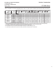
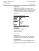
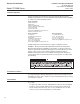
Table 1-5 Capacities and Pressure Drop Meter Sizes 2 thru 13: 127mm, 200mm, 250mm Scale, Rib Guided Tubes, Alarm Floats
****riAretaW
Flow Rate Pressure Drop V. I. C.** Flow Rate Pressure Drop REQ. REQ.
TUBE FLOAT GPM l/h INCHES W.C. kPa cSt SCFM m3n/h INCHES W.C. kPa psi(*) bar(*)
***6 & 2 seziS rof elbaT yticapaC ot refeR2 eziS
***6 & 2 seziS rof elbaT yticapaC ot
refeR6 eziS
Size 7 R-7M-25-1FT 7-XV-11A 0.48 100 8.0 2.0 3.0 1.9 3.0 10 2.5 0 0
Size 8 8-XV-14 1.4 320 8.0 2.0 5.4 6 9.2 8.0 2.0 0 0
R-8M-25-4FT 8-XS-14 1.8 410 10 2.5 1.9 8 11 11 2.8 0 0
Size 9 9-XV-40 2.8 630 6.0 1.5 11 10 18 7.0 1.8 0 0
R-9M-25-3FT 9-XS-40 3.5 810 4.0 1.0 2.4 13 22 8.0 2.0 0 0
Size 10 10-XV-64 6.2 1400 11 2.8 15 25 40 13 3.3 0 0
R-10M-25-3FT 10-XS-138 10 2400 30 7.5 5.5 45 75 36 9.0 30 2
Size 12 12-XV-221 17 3900 10 2.5 29 70 110 12 3.0 0 0
R-12M-20-5FT 12-XV-343 20 4700 16 4.0 36 94 150 18 4.5 30 2
Size 13 13-XV-510 31 7200 26 6.5 42 130 200 28 7.0 0 0
R-13M-20-3FT 13-XS-510 42 9600 36 9.0 7.6 170 270 40 10 0 0
13-XHF-758
62.00 14000 40 10 1.0 270 450 44 11 30 2
(*) Minimum operating downstream pressure for gas service (psig)
(**) Viscosity immunity ceiling listed is for stainless steel float, fluid specific gravity 1.0. When the viscosity of the flui
d exceeds the viscosity immunity
ceiling (VIC), a calculated correction is applied to account for the difference between factory calibration fluid and process fluid.
Note 1: All size 8-13 floats listed are 316 SS with integral magnet for use with reed switch alarm.
(***) Alarm option for sizes 2 and 6 requires metallic float (SS or carboloy) for use with inductive type alarm.
(****) Air flow rates in standard units are at 70'F and 14.7 PSIA, air flow rates in normal units are at 1.013 bar & 20'C