
User guide


ii
Contents
GT1000 Series
Installation and Operation Manual
X-VA-GT1000-eng
Part Number: 541B078AAG
March, 2014
Figures
Figure Page
Number Number
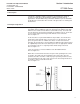
1-1 Principle of Operation .......................................................................................................................... 1-1
1-2 Cross-Section - GT1000 Flow Tubes with Rib Guides ........................................................................ 1-2
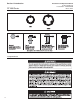
1-3 GT1000 Floats (Descriptions refer to floats used in the same size tube))........................................... 1-2
1-4 GT1000 Family: NPT, Flanged and w/AlarmOptions ........................................................................... 1-8
1-5 Alarm Switch(es) for GT1000 Sizes 7-13 ........................................................................................... 1-10
1-6 Dimensions and Specs, Intrinsically Safe Switch Isolators................................................................. 1-11
1-7 Alarm Wiring Diagram, Reed Switch & Inductive Alarm with Agency Approved Power Supply/Relay
Isolator Alarm Wiring Diagram, Reed Switch with Customer Supplied Barrier ................................... 1-12
2-1 Typical Flowmeter Piping Configuration .............................................................................................. 2-3
3-1 Typical Flowmeter Piping Configuration .............................................................................................. 3-2
5-1 GT1000, Sizes 2 and 6 Parts Assembly Drawing ................................................................................ 5-1
5-2 GT1000, Sizes 7-10 Parts Assembly Drawing ..................................................................................... 5-2
5-3 GT1000, Sizes 12 and 13 Parts Assembly Drawing ............................................................................ 5-3
Tables
Table Page
Number Number
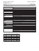
1-1 Specifications - GT1000 ...................................................................................................................... 1-3
1-2 GT1000 Pressure Ratings and PED Categories ................................................................................. 1-3
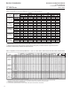
1-3 Capacities and Pressure Drop Meter Sizes 2 & 6: Spherical Floats .................................................... 1-4
1-4 Capacities and Pressure Drop Meter Sizes 7, 8, 9, 10, 12 & 13: 200mm, 250mm Scale, Rib Guided
Tubes, Standard Floats ................................................................................................................... 1-4
1-5 Capacities and Pressure Drop Meter Sizes 2 thru 13: 127mm, 200mm, 250mm Scale, Rib Guided
Tubes, Alarm Floats ........................................................................................................................ 1-5
1-6 Data 10&15-14-N3 Inductive Coils ...................................................................................................... 1-9
5-1 Parts Assembly Item Identification....................................................................................................... 5-4