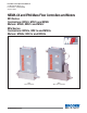
Installation and Operation Manual X-TMF-Mfi-Mfx-MFC-eng Part Number: 541B074AAG August, 2009 Brooks® Mf Series NEMA 4X and IP66 Mass Flow Controllers and Meters Mfi Series Controllers: Mf50i, Mf51i and Mf53i Meters: Mf60i, Mf61i and Mf63i Mfx Series Controllers: Mf50x, Mf51x and Mf53x Meters: Mf60x, Mf61x and Mf63x Mf61 Mass Flowmeter Mf50 Mass Flow Controller
Brooks® Mf Series Installation and Operation Manual X-TMF-Mfi-Mfx-MFC-eng Part Number: 541B074AAG August, 2009 Essential Instructions Read this page before proceeding! Brooks Instrument designs, manufactures and tests its products to meet many national and international standards. Because these instruments are sophisticated technical products, you must properly install, use and maintain them to ensure they continue to operate within their normal specifications.
Installation and Operation Manual X-TMF-Mfi-Mfx-MFC-eng Part Number: 541B074AAG August, 2009 Brooks® Mf Series Dear Customer, We appreciate this opportunity to service your flow measurement and control requirements with a Brooks Instrument device. Every day, flow customers all over the world turn to Brooks Instrument for solutions to their gas and liquid low-flow applications.
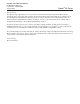
Brooks® Mf Series Installation and Operation Manual X-TMF-Mfi-Mfx-MFC-eng Part Number: 541B074AAG August, 2009 Mf Series Summary Installation Overview (shows cable gland option) Terminal Strip Label:
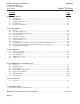
Installation and Operation Manual X-TMF-Mfi-Mfx-MFC-eng Part Number: 541B074AAG August, 2009 Paragraph Number Contents Brooks® Mf Series Page Number Section 1 Introduction 1-1 Description ................................................................................................................................. 1-1 1-2 Design Features ......................................................................................................................... 1-1 1-3 Principle of Operation .............
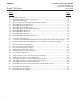
Contents Brooks® Mf Series Figure Number ii Installation and Operation Manual X-TMF-Mfi-Mfx-MFC-eng Part Number: 541B074AAG August, 2009 Page Number 1-1 1-2 1-3 1-4 1-5 1-6 1-7 1-8 1-9 1-10 1-11 1-12 Principle of Operation ................................................................................................................. 1-2 Maximum Allowable Output Loop Resistance ............................................................................ 1-5 Terminal Strip Labeling ...................
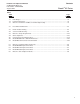
Installation and Operation Manual X-TMF-Mfi-Mfx-MFC-eng Part Number: 541B074AAG August, 2009 Tables Table Number Contents Brooks® Mf Series Page Number 1-1 1-2 1-3 Flow Ranges .............................................................................................................................. 1-2 Power Requirements .................................................................................................................. 1-4 Mf Series Controllers and Meters Terminal Strip Hookup ......
Contents Installation and Operation Manual X-TMF-Mfi-Mfx-MFC-eng Part Number: 541B074AAG August, 2009 Brooks® Mf Series THIS PAGE WAS INTENTIONALLY LEFT BLANK iv
Installation and Operation Manual X-TMF-Mfi-Mfx-MFC-eng Part Number: 541B074AAG August, 2009 Section 1 Introduction Brooks® Mf Series 1-1 Description The Brooks® MfTM Series mass flow controllers and meters are specifically designed to be used in an industrial environment. These controllers and meters offer high accuracy, control and measurement of industrial gases with the added integrity of NEMA 4X, IP66 industrial packaging.
Section 1 Introduction Installation and Operation Manual X-TMF-Mfi-Mfx-MFC-eng Part Number: 541B074AAG August, 2009 Brooks® Mf Series and positions the precision solenoid control valve. When the command signal is below 1% of full scale, the control valve is positioned to fully closed. The control valve can be latched fully open or closed by activating the valve override circuit.
Section 1 Introduction Installation and Operation Manual X-TMF-Mfi-Mfx-MFC-eng Part Number: 541B074AAG August, 2009 Brooks® Mf Series Repeatability 0.25% of rate Sensitivity to Mounting Attitude ±0.5% full scale maximum deviation from specified accuracy after re-zeroing under 200 psig. Specify mounting attitude at time of order to insure optimum performance. Temperature Sensitivity Zero: Less than ±0.075% F.S. per degree C Span: Less than ±1.0% F.S.
Section 1 Introduction Installation and Operation Manual X-TMF-Mfi-Mfx-MFC-eng Part Number: 541B074AAG August, 2009 Brooks® Mf Series 1-5 Electrical Specifications Setpoint Command Requirements (Controllers) 4-20 mA (75 ohms input resistance). The 4-20mA setpoint signal must be supplied from the customers side(sourcing type). The input load for this signal is 75 ohms.
Section 1 Introduction Installation and Operation Manual X-TMF-Mfi-Mfx-MFC-eng Part Number: 541B074AAG August, 2009 Brooks® Mf Series Table 1-3 Mf Series Controllers and Meters Terminal Strip Hookup TB-1 Label Terminal 1-6 Identification 1 VSUP 2 SUPCOM 3 NC 4 SUPCOM 5 VSIG 6 ISIG TB-2 Label Terminal 1-9 Identification 1 NC 2 GND 3 NC 4 VREF 5 VOR 6 NC 7 CMDCOM 8 VCMD 9 ICMD TB-3 Label Terminal 1 & 2 Identification 1 NONE 2 NONE Function Supply Voltage Plus (+) See Table 3 Supply Voltage Common Not Used
Section 1 Introduction Installation and Operation Manual X-TMF-Mfi-Mfx-MFC-eng Part Number: 541B074AAG August, 2009 Brooks® Mf Series TB-1 VALVE IG IS IG VS OM C G SI Figure 1-3 Terminal Strip Labeling Figure 1-4 Mf Series Typical Hookup to Brooks 0151i Power Supply 1-6 C D N G N VO R VR EF N C C C N M D D C M VC IC M D O M U C N OM PC SU + P VS TB-2 TB-3
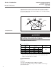
Installation and Operation Manual X-TMF-Mfi-Mfx-MFC-eng Part Number: 541B074AAG August, 2009 Section 1 Introduction Brooks® Mf Series Connections 9/16 -18 UNF 1/4" Tube Compr. 1/8" Tube Compr. 1/4" VCRTM 1/4" VCOTM 1/4" NPT 6mm Tube Compr. "A" Dim. 5.28/134 7.30/185 7.13/181 7.17/182 6.85/174 6.89/175 7.32/186 Dimensions in inches/mm Figure 1-5 Model Mf50 Controller Dimensions Connections 9/16 -18 UNF 1/4" Tube Compr. 3/8" Tube Compr. 1/4" VCR 1/4" VCO "A" Dim. 5.85/148.5 7.87/199.9 7.99/203.0 7.
Section 1 Introduction Brooks® Mf Series Installation and Operation Manual X-TMF-Mfi-Mfx-MFC-eng Part Number: 541B074AAG August, 2009 Connections 1/2" Tube Compr. 3/4" Tube Compr. 1" Tube Compr. 1/2" VCO 3/4" VCO 1/2" VCR 0.5", 0.1", 1.5" NPT or 1-1/16"-12 "A" Dim. 11.96/303.8 11.96/303.8 12.31/312.8 10.86/275.8 11.57/293.8 11.17/283.8 9.28/235.8 Dimensions in inches/mm Figure 1-7 Model Mf53 Controller Dimensions Flange DIN DN14 DIN DN25 DIN DN40 DIN DN50 ANSI 0.5" ANSI 0.5" ANSI 1" ANSI 1" ANSI 1.
Installation and Operation Manual X-TMF-Mfi-Mfx-MFC-eng Part Number: 541B074AAG August, 2009 Section 1 Introduction Brooks® Mf Series Connections 9/16 -18 UNF 1/4" Tube Compr. 1/8" Tube Compr. 1/4" VCR 1/4" VCO 1/4" NPT 6 mm Tube Compr. "A" Dim. 3.89/98.7 5.93/150.7 5.74/145.7 5.78/146.7 5.46/138.7 5.50/139.7 5.93/150.7 Dimensions in inches/mm Figure 1-9 Model Mf60 Meter Dimensions Connections 9/16 -18 UNF 1/4" Tube Compr. 3/8" Tube Compr. 1/4" VCR 1/4" VCO "A" Dim. 4.45/113.1 6.48/164.5 6.60/167.
Section 1 Introduction Brooks® Mf Series Installation and Operation Manual X-TMF-Mfi-Mfx-MFC-eng Part Number: 541B074AAG August, 2009 Connections 1/2" Tube Compr. 3/4" Tube Compr. 1" Tube Compr. 1/2" VCO 3/4" VCO 1/2" VCR 0.5", 1", 1.5" NPT or 1-1/16" - 12 "A" Dim. 10.23/260 10.23/260 10.59/269 9.13/232 9.84/250 9.44/240 7.55/192 Dimensions in inches/mm Figure 1-11 Model Mf63 Meter Dimensions Flange DIN DN15 DIN DN25 DIN DN40 DIN DN50 ANSI 0.5" ANSI 0.5" ANSI 1" ANSI 1" ANSI 1.5" ANSI 1.
Section 2 Installation Installation and Operation Manual X-TMF-Mfi-Mfx-eng Part Number: 541B074AAG August, 2009 Brooks® Mf Series 2-1 General This section contains the procedures for the receipt and installation of the instrument. See Section 1 for dimensional and connection requirements. Do not attempt to start the system until the instrument has been permanently installed. It is important that the start-up procedures be followed in the exact sequence presented.
Section 2 Installation Installation and Operation Manual X-TMF-Mfi-Mfx-eng Part Number: 541B074AAG August, 2009 Brooks® Mf Series 2-4 Return Shipment Prior to returning any instrument to the factory, contact your nearest Brooks location for a Return Materials Authorization Number (RMA#). This can be obtained from one of the following locations: Brooks Instrument 407 W. Vine Street P.O.
Section 2 Installation Installation and Operation Manual X-TMF-Mfi-Mfx-eng Part Number: 541B074AAG August, 2009 Brooks® Mf Series 2-7 Gas Connections Refer to Tables 5-1 through 5-4 for the available process connection types and sizes. It is recommended that good tubing and piping practice be followed. It is also recommended that for very low flows in meter size Mf50's that tubing 1/4 or less be used and for flows over 10 slpm 3/8 tubing be applied.
Section 2 Installation Brooks® Mf Series Installation and Operation Manual X-TMF-Mfi-Mfx-eng Part Number: 541B074AAG August, 2009 Recommended installation procedures: a. The Mf Series instrument should be located in an environment relatively free from shock and vibration. b. Leave sufficient room for access to the electrical components. c. Install in such a manner that permits easy removal if the instrument requires cleaning.
Section 2 Installation Installation and Operation Manual X-TMF-Mfi-Mfx-eng Part Number: 541B074AAG August, 2009 Brooks® Mf Series pressures and/or pressure differentials that the Mf53 is exposed to may be different from the final process conditions. For higher pressure applications, and especially those with the low force bellows, it is important to bring the pressure up in a controlled manner in order to prevent a possible pressure spike to the bellows spring and main valve diaphragm.
Section 2 Installation Brooks® Mf Series Figure 2-1 Common Electrical Hookups 2-6 Installation and Operation Manual X-TMF-Mfi-Mfx-eng Part Number: 541B074AAG August, 2009
Installation and Operation Manual X-TMF-Mfi-Mfx-eng Part Number: 541B074AAG August, 2009 Section 2 Installation Brooks® Mf Series Figure 2-2 Recommended I/O Wiring Configuration for Current Signals (Non-Isolated Power Supply) Figure 2-3 Recommended I/O Wiring Configuration for Current Signals (Isolated Power Supply) 2-7
Section 2 Installation Installation and Operation Manual X-TMF-Mfi-Mfx-eng Part Number: 541B074AAG August, 2009 Brooks® Mf Series 2-10 Electrical Interfacing (Electrical Specifications Refer to Section 1-5) To insure proper operation, the Mf device must be connected per Figures Figure 1-2 (Maximum Allowable Loop Resistance); Figure 1-3 and Table 1-3 (Terminal Strip Hookup); and Figures1-7 through 1-12 (Dimension Drawings). Configure in accordance to Section 2-9 and Figure 3-5.
Section 2 Installation Installation and Operation Manual X-TMF-Mfi-Mfx-eng Part Number: 541B074AAG August, 2009 Brooks® Mf Series Chassis Ground Connect earth ground to TB-2, Terminal 2. Valve Override - Controller Only (connection optional) The valve override function allows full opening and closing of the valve independent of the setpoint: • To open the valve, apply voltage (15-24) Vdc to TB-2, Terminal 5. • To close the valve, connection TB-2, Terminal 5 to power supply common.
Section 2 Installation Installation and Operation Manual X-TMF-Mfi-Mfx-eng Part Number: 541B074AAG August, 2009 Brooks® Mf Series THIS PAGE WAS INTENTIONALLY LEFT BLANK 2-10
Section 3 Operation Installation and Operation Manual X-TMF-Mfi-Mfx-MFC-eng Part Number: 541B074AAG August, 2009 Brooks® Mf Series 3-1 Theory of Operation The thermal mass flow sensing technique used in the Mf Series works as follows: A precision power supply provides a constant power heat input (P) to the heater which is located at the midpoint of the sensor tube. Refer to Figure 3-1. At zero or no flow conditions, the heat reaching each temperature sensor is equal.
Section 3 Operation Installation and Operation Manual X-TMF-Mfi-Mfx-MFC-eng Part Number: 541B074AAG August, 2009 Brooks® Mf Series • Precision 5 Volt Reference allows the direct connection of a setpoint potentiometer to produce a 0-5 Volt command signal to the controller. A precision ten-turn 2 K ohm potentiometer with an integral turns counter is recommended. This will permit repeatable adjustments of setpoint to 1 part in 1,000.
Section 3 Operation Installation and Operation Manual X-TMF-Mfi-Mfx-MFC-eng Part Number: 541B074AAG August, 2009 Brooks® Mf Series 3-3 Zero Adjustment Each Mf Series controller and meter is factory adjusted to provide a zero ±10 mVdc signal or a 4 mAdc ±.05 mAdc signal at zero flow. The adjustment is made in our calibration laboratory which is temperature controlled to 21.1°C (70°F ±2°F).
Section 3 Operation Installation and Operation Manual X-TMF-Mfi-Mfx-MFC-eng Part Number: 541B074AAG August, 2009 Brooks® Mf Series 3-4 Calibration Procedure Note 1: If the valve has been disassembled and any of the following parts have been replaced, the control valve adjustment procedure in Section 44c must be performed before the Mf Series instrument is calibrated.
Section 3 Operation Installation and Operation Manual X-TMF-Mfi-Mfx-MFC-eng Part Number: 541B074AAG August, 2009 Brooks® Mf Series f. Connect the DVM positive lead to TP1 (100x sensor voltage) and the negative lead to TP4 (circuit common). The setpoint should still be set at 100% flow (5.000 V). Measure the flow rate using a suitable volumetric calibration equipment.
Section 3 Operation Installation and Operation Manual X-TMF-Mfi-Mfx-MFC-eng Part Number: 541B074AAG August, 2009 Brooks® Mf Series stabilized for at least two minutes. Repeat this check and adjustment procedure until the measured flow rate is within 1% of the desired flow rate. Note: The voltage at TP1 is 100 times the output voltage of the sensor. This voltage can range from 1.2 to 12 Volts, however, it is recommended that this voltage stays between 2.0 and 9.0 Volts for proper operation.
Section 3 Operation Installation and Operation Manual X-TMF-Mfi-Mfx-MFC-eng Part Number: 541B074AAG August, 2009 Brooks® Mf Series Example: What is the percent of full scale error when full scale is equal to 100 sccm? Measure flow rate = 48.5 sccm Desired flow rate = 50.0 sccm i. Calculate the TP2 correction voltage: (error recorded in Step h) x 0.450 Volts Example: Error = -1.5% TP2 correction voltage = -1.5 x 0.450 = -0.675 Volts New TP2 voltage = 0 Volts + (-0.675) = -0.675 Volts j.
Section 3 Operation Installation and Operation Manual X-TMF-Mfi-Mfx-MFC-eng Part Number: 541B074AAG August, 2009 Brooks® Mf Series 3-5 Response Fast Response Adjustment (Controller) Two methods of adjusting the step response of the Mf Series mass flow controllers can be used. Number 1 below, describes a method that will get the step response close to optimum quickly and without any flow measuring equipment.
Installation and Operation Manual X-TMF-Mfi-Mfx-MFC-eng Part Number: 541B074AAG August, 2009 Section 3 Operation Brooks® Mf Series seconds after setpoint change requires the use of a fast response flowmeter (500 millisecond response to be within 0.2% of final value or better) in series with the Mf Series and a storage oscilloscope or recorder. a. Allow the flow controller to stabilize at 0% setpoint for at least thirty seconds.
Section 3 Operation Installation and Operation Manual X-TMF-Mfi-Mfx-MFC-eng Part Number: 541B074AAG August, 2009 Brooks® Mf Series THIS PAGE WAS INTENTIONALLY LEFT BLANK 3-10
Installation and Operation Manual X-TMF-Mfi-Mfx-MFC-eng Part Number: 541B074AAG August, 2009 Section 4 Maintenance & Troubleshooting Brooks® Mf Series 4-1 General WARNING It becomes necessary to remove the instrument from the system after exposure to toxic, pyrophoric, flammable or corrosive gas, purge the controller thoroughly with a dry inert gas such as nitrogen before disconnecting the gas connections. Failure to correctly purge the controller could result in fire, explosion or death.
Section 4 Maintenance & Troubleshooting Brooks® Mf Series Installation and Operation Manual X-TMF-Mfi-Mfx-MFC-eng Part Number: 541B074AAG August, 2009 This product contains elastomers that are used to seal the process gas and also to maintain a water tight and dust tight enclosure. Elastomers will deteriorate and fail over time. The elastomer seals used in this product have a maximum shelf life of five years, but severe service conditions may shorten their lifetime.
Section 4 Maintenance & Troubleshooting Installation and Operation Manual X-TMF-Mfi-Mfx-MFC-eng Part Number: 541B074AAG August, 2009 Brooks® Mf Series Table 4-1 Bench Troubleshooting Trouble Possible Cause Check/Corrective Action Actual flow overshoots controller setpoint by more than 5% full scale.* Anticipate potentiometer out of adjustment Adjust anticipate potentiometer. Refer to Section 3-5. Output stays at zero and there is flow through instrument Clogged sensor. Clean sensor.
Section 4 Maintenance & Troubleshooting Brooks® Mf Series Installation and Operation Manual X-TMF-Mfi-Mfx-MFC-eng Part Number: 541B074AAG August, 2009 CAUTION When used with a reactive (sometimes toxic) gas, contamination or corrosion may occur as a result of plumbing leaks or improper purging. Plumbing should be checked carefully for leaks and the controller purged with dry Nitrogen before use. B. Bench Troubleshooting 1.
Section 4 Maintenance & Troubleshooting Installation and Operation Manual X-TMF-Mfi-Mfx-MFC-eng Part Number: 541B074AAG August, 2009 Brooks® Mf Series 2. Connect the instrument to a source of gas on which it was originally calibrated. Adjust the setpoint for 100% flow. Adjust flow to 100% indication (5.00 V) and adjust the inlet and outlet pressures to the calibration conditions. Verify that the output signal reaches and stabilizes at 5.00 Volts or 20 mA.
Section 4 Maintenance & Troubleshooting Brooks® Mf Series Installation and Operation Manual X-TMF-Mfi-Mfx-MFC-eng Part Number: 541B074AAG August, 2009 3. The Mfx Series sensor is not removable. The controller and meter should be disassembled following the instructions in Section 4-4. The sensor/body assembly can then be inspected for contamination and purged with clean, dry Nitrogen. The remaining component parts may be immersed in a deionized water bath using ultrasonic agitation to enhance cleaning.
Installation and Operation Manual X-TMF-Mfi-Mfx-MFC-eng Part Number: 541B074AAG August, 2009 Section 4 Maintenance & Troubleshooting Brooks® Mf Series 4-3 Sensor Tube The sensor tube is part of a calibrated flow divider that is designed to operate within a preset gas flow range. The Mfi Series sensor assembly may be removed or replaced by referring to Section 4-4, disassembly and assembly. If the sensor assembly is cleaned and reinstalled, a calibration check should be performed. Refer to Section 3-4.
Section 4 Maintenance & Troubleshooting Brooks® Mf Series Installation and Operation Manual X-TMF-Mfi-Mfx-MFC-eng Part Number: 541B074AAG August, 2009 4. Carefully remove the valve stem assembly (24). 5. Remove the plunger assembly (26, 29, 28B and 32). 6. Remove and note the position of the valve spring spacers (28A) which may be located above and/or below the lower valve springs (29). 7. Unscrew the orifice (33) from the flow controller body. 8.
Installation and Operation Manual X-TMF-Mfi-Mfx-MFC-eng Part Number: 541B074AAG August, 2009 Section 4 Maintenance & Troubleshooting Brooks® Mf Series Figure 4-2 Voltmeter Connections for Valve Adjustment 17.For Mf51/61, remove the four screws from the end block and carefully remove the end block. B. Assembly (Mfx Series sensor assembly is not removable) Note: It is recommended that all service O-rings be replaced during instrument assembly.
Section 4 Maintenance & Troubleshooting Installation and Operation Manual X-TMF-Mfi-Mfx-MFC-eng Part Number: 541B074AAG August, 2009 Brooks® Mf Series 3. For Mf51/61, place the end block O-ring in position and install the end block with the 4 hex socket screws. 4. (Mfi Series only), press the lubricated sensor O-rings (25B) into the flow controller body. Install the sensor assembly and secure with two screws (37) and washers (38) and tighten. 5.
Section 4 Maintenance & Troubleshooting Installation and Operation Manual X-TMF-Mfi-Mfx-MFC-eng Part Number: 541B074AAG August, 2009 Brooks® Mf Series 10.Install the coil assembly (21) over the valve stem assembly (24) and secure with jam nut (20). Make sure O-rings (1) are installed on retaining plate (23) and jam nut (20). 11.Install the PC board (20) and two screws. Plug the connector from the sensor assembly onto the PC board.
Section 4 Maintenance & Troubleshooting Brooks® Mf Series Figure 4-3a Valve Adjusting Spacer Locations ( Normally Closed Valve ) 4-12 Installation and Operation Manual X-TMF-Mfi-Mfx-MFC-eng Part Number: 541B074AAG August, 2009
Installation and Operation Manual X-TMF-Mfi-Mfx-MFC-eng Part Number: 541B074AAG August, 2009 Section 4 Maintenance & Troubleshooting Brooks® Mf Series Figure 4-3b Valve Adjusting Spacer Locations ( Normally Open Valve ) 4-13
Section 4 Maintenance & Troubleshooting Brooks® Mf Series Installation and Operation Manual X-TMF-Mfi-Mfx-MFC-eng Part Number: 541B074AAG August, 2009 The preload determines the initial force that is required to raise the valve seat off the orifice and start gas flow. If the preload is insufficient, the valve will not fully close and gas will leak through.
Installation and Operation Manual X-TMF-Mfi-Mfx-MFC-eng Part Number: 541B074AAG August, 2009 Section 4 Maintenance & Troubleshooting Brooks® Mf Series i. Measure the valve voltage by connecting a voltmeter between Test Point 3 (TP3) and Test Point 4 (TP4). Refer to Figure 4-3. j1. If the flow controller output signal is 100% and the valve voltage is less than 11.5 V, the valve adjustment is complete. j2. If the flow controller output signal is 100% and the valve voltage is greater than 11.
Section 4 Maintenance & Troubleshooting Installation and Operation Manual X-TMF-Mfi-Mfx-MFC-eng Part Number: 541B074AAG August, 2009 Brooks® Mf Series Table 4-4 Orifice Capacities Orifice Size (inches) Minimum Flow Rate (sccm) 32°F (0°C) 70°F (21.1°C) 5.3 (5.7) 12.5 (13.5) 39.2 (42.2) 82.5 (88.9) 190 (205) 374 (403) 748 (806) 1364 (1469) 2673 (2879) 6490 (6991) 12980 (13980) 22000 (2879) 31900 (34400) 42500 (45800) 69300 (74700) 95,500 (103,000) 108,200 (116,600) 0.0013 0.002 0.003 0.004 0.0055 0.
Installation and Operation Manual X-TMF-Mfi-Mfx-MFC-eng Part Number: 541B074AAG August, 2009 Section 4 Maintenance & Troubleshooting Brooks® Mf Series If adding two 0.005” thick large diameter flow clearance spacers for controllers with 0.007” and greater orifices or removing both 0.002” thick small diameter flow clearance spacers for orifices less than 0.007” does not provide adequate flow, the orifice size should be checked. See Section 4-6, Orifice Sizing.
Section 4 Maintenance & Troubleshooting Installation and Operation Manual X-TMF-Mfi-Mfx-MFC-eng Part Number: 541B074AAG August, 2009 Brooks® Mf Series 4-5 Gas Conversion Factors If a mass flow controller is operated on a gas other than the gas it was calibrated with, a scale shift will occur in the relation between the output signal and the mass flow rate. This is due to the difference in heat capacities between the two gases.
Section 4 Maintenance & Troubleshooting Installation and Operation Manual X-TMF-Mfi-Mfx-MFC-eng Part Number: 541B074AAG August, 2009 Brooks® Mf Series Table 4-5 Conversion Factors (Nitrogen Base) GAS NAME Acetylene Air Allene Ammonia Argon Arsine Boron Trichloride Boron Trifluoride Bromine Pentafluoride Bromine Trifluoride Bromotrifluoroethylene Bromotrifluoromethane f-13B1 1,3-Butadiene Butane 1-Butene CIS-2-Butene Trans-2-Butene Carbon Dioxide Carbon Disulfide Carbon Monoxide Carbon Tetrachloride Carbo
Section 4 Maintenance & Troubleshooting Installation and Operation Manual X-TMF-Mfi-Mfx-MFC-eng Part Number: 541B074AAG August, 2009 Brooks® Mf Series Table 4-5 Conversion Factors (Nitrogen Base) Continued GAS NAME Ethylene Ethylene Oxide Fluorine Fluoroform f-23 Germane Germanium Tetrachloride Halothane (R-123B1) Helium Hexafluoroacetone Hexaflorobenzine Hexafluoroethane f-116 Hexafuoropropylene (HFP) Hexamethyldisilane (HMDS) Hexane Hydrogen Hydrogen Bromide Hydrogen Chloride Hydrogen Cyanide Hydrogen F
Section 4 Maintenance & Troubleshooting Installation and Operation Manual X-TMF-Mfi-Mfx-MFC-eng Part Number: 541B074AAG August, 2009 Brooks® Mf Series Table 4-5 Conversion Factors (Nitrogen Base) Continued GAS NAME FORMULA Pentane (n-Pentane) Phosgene Phosphine Phosphorous Pentafluoride Phosphorous Trifluoride Propane (same as CH3CH2CH 3) Propylene (Propene) Rhenium Hexafluoride Silane Silicon Tetrachloride Silicon Tetrafluoride Sulfur Dioxide Sulfur Hexafluoride Sulfur Tetrafluoride Sulfur Trioxide Su
Section 4 Maintenance & Troubleshooting Installation and Operation Manual X-TMF-Mfi-Mfx-MFC-eng Part Number: 541B074AAG August, 2009 Brooks® Mf Series 4-6 Restrictor Sizing The restrictor assembly is a ranging device for the sensor portion of of the controller/meter. It creates a pressure drop which is linear with flow rate. This diverts a sample quantity of the process gas flow through the sensor.
Installation and Operation Manual X-TMF-Mfi-Mfx-MFC-eng Part Number: 541B074AAG August, 2009 Section 4 Maintenance & Troubleshooting Brooks® Mf Series Restrictor assembly replacement should be performed only by trained personnel. The tools required for the removal/replacement procedure are as follows: 1. Appropriate size wrench for the removal of the inlet process connection. 2. Restrictor removal tool (contained service tool kit P/N S778D017AAA) 3.
Section 4 Maintenance & Troubleshooting Installation and Operation Manual X-TMF-Mfi-Mfx-MFC-eng Part Number: 541B074AAG August, 2009 Brooks® Mf Series Figure 4-4 Model Mf51/61 Restrictor Element Assembly 5. Install the inlet adapter fitting and O-ring. 6. Recalibration of the controller or meter should be considered in order to maintain correct accuracy. Table 4-7 Model Mf51/61 Restrictor Selection Guide Full Scale Range slpm Nitrogen Equivalent Flow* 4.
Installation and Operation Manual X-TMF-Mfi-Mfx-MFC-eng Part Number: 541B074AAG August, 2009 Section 4 Maintenance & Troubleshooting Brooks® Mf Series 4-7 Orifice Sizing Orifice sizes for all Mf controllers should be sized using the "Brooks Thermal Mass Flowmeter Sizing Selection Program" Revision 8.6 or later. A copy can be requested through your local Brooks Sales Representative or through the Brooks Customer Service Department.
Section 4 Maintenance & Troubleshooting Installation and Operation Manual X-TMF-Mfi-Mfx-MFC-eng Part Number: 541B074AAG August, 2009 Brooks® Mf Series THIS PAGE WAS INTENTIONALLY LEFT BLANK 4-26
Section 5 Parts List Installation and Operation Manual X-TMF-Mfi-Mfx-MFC-eng Part Number: 541B074AAG August, 2009 Brooks® Mf Series 5-1 General When ordering parts, please specify: • Brooks Serial Number • Model Number • Part Description • Part Number • Quantity Refer to Figures 5-1 through 5-3 for exploded parts drawings and Tables 5-1 through 5-4 for parts lists.
Section 5 Parts List Brooks® Mf Series Figure 5-1 Model Mf50/60 Parts Drawing 5-2 Installation and Operation Manual X-TMF-Mfi-Mfx-MFC-eng Part Number: 541B074AAG August, 2009
Installation and Operation Manual X-TMF-Mfi-Mfx-MFC-eng Part Number: 541B074AAG August, 2009 Section 5 Parts List Brooks® Mf Series Figure 5-2 Model Mf51/61 Parts Drawing 5-3
Section 5 Parts List Brooks® Mf Series Figure 5-3 Model Mf53/63 Parts Drawing 5-4 Installation and Operation Manual X-TMF-Mfi-Mfx-MFC-eng Part Number: 541B074AAG August, 2009
Installation and Operation Manual X-TMF-Mfi-Mfx-MFC-eng Part Number: 541B074AAG August, 2009 Section 5 Parts List Brooks® Mf Series Table 5-1 Mf Series Common Replacement Parts *These parts are used only for controllers (Models Mf50i/51i/53i) 5-5
Section 5 Parts List Brooks® Mf Series Table 5-2 Mf50/60 Replacement Parts *These parts are used only for controller (Model Mf50) 5-6 Installation and Operation Manual X-TMF-Mfi-Mfx-MFC-eng Part Number: 541B074AAG August, 2009
Installation and Operation Manual X-TMF-Mfi-Mfx-MFC-eng Part Number: 541B074AAG August, 2009 Section 5 Parts List Brooks® Mf Series Table 5-3 Mf51/61 Replacement Parts *These parts are used only for controller (Model Mf51) 5-7
Section 5 Parts List Brooks® Mf Series Table 5-4 Mf53/63 Replacement Parts *These parts are used only for controller (Model Mf53) 5-8 Installation and Operation Manual X-TMF-Mfi-Mfx-MFC-eng Part Number: 541B074AAG August, 2009
Section 5 Parts List Installation and Operation Manual X-TMF-Mfi-Mfx-MFC-eng Part Number: 541B074AAG August, 2009 Brooks® Mf Series Table 5-5 Mf Series Tool and Spare Part Kits Mfi Service Tool Kit P/N S778D017AAA B. Permits the complete disassembly of the Mf Series for servicing Contains: 1 - .010" Large Spacer 2 - .005" Large Spacers 1 - .010" Small Spacer 2 - .
Section 5 Parts List Installation and Operation Manual X-TMF-Mfi-Mfx-MFC-eng Part Number: 541B074AAG August, 2009 Brooks® Mf Series THIS PAGE WAS INTENTIONALLY LEFT BLANK 5-10
Installation and Operation Manual X-TMF-Mfi-Mfx-MFC-eng Part Number: 541B074AAG August, 2009 Section A, CE Certification of Mass Flow Equipment Brooks® Mf Series Dansk Brooks Instrument 407 West Vine St. Hatfield, PA 19440 U.S.A. Emne : Tillæg til instruktions manual. Reference : CE mærkning af Masse Flow udstyr Dato : Januar-1996. Brooks Instrument har gennemført CE mærkning af elektronisk udstyr med succes, i henhold til regulativet om elektrisk støj (EMC direktivet 89/336/EEC).
Section A, CE Certification of Mass Flow Equipment Brooks® Mf Series Installation and Operation Manual X-TMF-Mfi-Mfx-MFC-eng Part Number: 541B074AAG August, 2009 English Brooks Instrument 407 West Vine St. Hatfield, PA 19440 U.S.A. Subject : Addendum to the Instruction Manual. Reference : CE certification of Mass Flow Equipment Date : January-1996.
Installation and Operation Manual X-TMF-Mfi-Mfx-MFC-eng Part Number: 541B074AAG August, 2009 Section A, CE Certification of Mass Flow Equipment Brooks® Mf Series Français Brooks Instrument 407 West Vine St. Hatfield, PA 19440 U.S.A. Sujet : Annexe au Manuel d’Instructions. Référence : Certification CE des Débitmètres Massiques à Effet Thermique. Date : Janvier 1996.
Section A, CE Certification of Mass Flow Equipment Brooks® Mf Series Installation and Operation Manual X-TMF-Mfi-Mfx-MFC-eng Part Number: 541B074AAG August, 2009 Italiano Brooks Instrument 407 West Vine St. Hatfield, PA 19440 U.S.A. Oggetto : Addendum al manuale di istruzioni. Riferimento : Certificazione CE dei misuratori termici di portata in massa Data : Gennaio 1996.
Installation and Operation Manual X-TMF-Mfi-Mfx-MFC-eng Part Number: 541B074AAG August, 2009 Norsk Brooks Instrument 407 West Vine St. Hatfield, PA 19440 U.S.A.
Section A, CE Certification of Mass Flow Equipment Brooks® Mf Series Installation and Operation Manual X-TMF-Mfi-Mfx-MFC-eng Part Number: 541B074AAG August, 2009 Suomi Brooks Instrument 407 West Vine St. Hatfield, PA 19440 U.S.A. Asia : Lisäys Käyttöohjeisiin Viite : Massamäärämittareiden CE sertifiointi Päivämäärä : Tammikuu 1996 Brooksin CE merkillä varustetut sähköiset laitteet ovat läpäissyt EMC testit (direktiivi 89/336/EEC). Erityistä huomiota on kuitenkin kiinnitettävä signaalikaapelin valintaan.
Installation and Operation Manual X-TMF-Mfi-Mfx-MFC-eng Part Number: 541B074AAG August, 2009 Brooks® Mf Series THIS PAGE WAS INTENTIONALLY LEFT BLANK
Brooks® Mf Series Installation and Operation Manual X-TMF-Mfi-Mfx-MFC-eng Part Number: 541B074AAG August, 2009 LIMITED WARRANTY Seller warrants that the Goods manufactured by Seller will be free from defects in materials or workmanship under normal use and service and that the Software will execute the programming instructions provided by Seller until the expiration of the earlier of twelve (12) months from the date of initial installation or eighteen (18) months from the date of shipment by Seller.