Installation and Operation Manual X-VA-MT3809-3819-eng Part Number: 541B049AHG September, 2008 Models MT 3809 & 3819 5 Brooks® Model MT 3809 and 3819 Metal Tube Variable Area Flowmeters with Optional Electronics Based on Smart Meter ManagerTM Technology Model MT 3809
Installation and Operation Manual Models MT 3809 & 3819 X-VA-MT3809-3819-eng Part Number: 541B049AHG September, 2008 Essential Instructions Read this page before proceeding! Brooks Instrument designs, manufactures and tests its products to meet many national and international standards. Because these instruments are sophisticated technical products, you must properly install, use and maintain them to ensure they continue to operate within their normal specifications.
Installation and Operation Manual X-VA-MT3809-3819-eng Part Number: 541B049AHG September, 2008 Models MT 3809 & 3819 Dear Customer, We appreciate this opportunity to service your flow measurement and control requirements with a Brooks Instrument device. Every day, flow customers all over the world turn to Brooks Instrument for solutions to their gas and liquid low-flow applications.
Installation and Operation Manual X-VA-MT3809-3819-eng Part Number: 541B049AHG September, 2008 Models MT 3809 & 3819 THIS PAGE WAS INTENTIONALLY LEFT BLANK
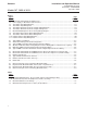
Installation and Operation Manual X-VA-MT3809-3819-eng Part Number: 541B049AHG September, 2008 Contents Models MT 3809 & 3819 Section 1 Introduction Paragraph Page Number Number 1-1 Description ....................................................................................................................................... 1-1 1-2 Design Features ...............................................................................................................................
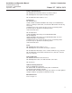
Contents Models MT 3809 & 3819 Installation and Operation Manual X-VA-MT3809-3819-eng Part Number: 541B049AHG September, 2008 Figures Figure Page Number Number 1-1 Models MT 3809 and MT 3819 Dimensions ..................................................................................... 1-6 1-2 Power Supply vs. Maximum Load Resistance ................................................................................. 1-9 1-3 Transmitter Only Wiring Diagram ..................................................
Section 1 Introduction Installation and Operation Manual X-VA-MT3809-3819-eng Part Number: 541B049AHG September, 2008 Models MT 3809 & 3819 1-1 Description The Brooks® Models MT 3809 and MT 3819 Variable Area Flowmeters are rugged, all metal flowmeters offering 2% full scale accuracy.
Section 1 Introduction Installation and Operation Manual X-VA-MT3809-3819-eng Part Number: 541B049AHG September, 2008 Models MT 3809 & 3819 Repeatability 0.25% Full Scale Pressure Ratings Refer to Table 1-2 for Model MT 3809 maximum non-shock pressure. Model MT 3819 pressure rating is dependant on flange rating.
Installation and Operation Manual X-VA-MT3809-3819-eng Part Number: 541B049AHG September, 2008 Section 1 Introduction Models MT 3809 & 3819 Flanges and End Fittings MT 3809 Standard: 316/316L stainless steel dual certified MT 3809 Optional: Hastelloy B, Hastelloy C, titanium MT 3819 Standard: 316L stainless steel Connections MT 3809 Standard: 150 lbs, 300 lbs or 600 lbs RF ANSI B 16.
Section 1 Introduction Installation and Operation Manual X-VA-MT3809-3819-eng Part Number: 541B049AHG September, 2008 Models MT 3809 & 3819 Table 1-1A Model MT 3809 Capacities, Pressure Drop and Viscosity Immunity Ceiling METER SIZE CONNECTION SIZE DIN ANSI DN mm inches 15 1/2" 7 15 1/2" 25 1" 40 1 1/2" 50 2" 80 3" 100 4" 8 10 12 13 15 16 FLOAT CODE A B* C D* A B C D A B C D A B C D A B C D A B C A B C WATER l/h gpm 25 0.11 65 0.28 130 0.59 200 0.88 250 1.1 400 1.7 650 2.8 1000 4.
Section 1 Introduction Installation and Operation Manual X-VA-MT3809-3819-eng Part Number: 541B049AHG September, 2008 Models MT 3809 & 3819 Table 1-2 Model MT 3809 Pressure Ratings* 316/316L Stainless Steel (psig at indicated temperature) Flange Rating** -20°F to 100°F 200°F 300°F 400°F 500°F 600°F 617°F 150 lb. 275 240 215 195 170 140 134 448 899 300 lb. 720 620 560 515 480 450 600 lb.
Section 1 Introduction Installation and Operation Manual X-VA-MT3809-3819-eng Part Number: 541B049AHG September, 2008 Models MT 3809 & 3819 Model MT 3809 with NPT-F Connections mm (inches)* D B A± 2 D 135 (5.31) 108 (4.25) E C 104 (4.10) 122 (4.80) A B C D E WEIGHT (Approx.)** 1/2" NPT-F 225 (8.85) 88 (3.46) 72 (2.83) 53 (2.09) 59 (2.32) 1.3 kg (3 lbs.) 10 1" NPT-F 300 (11.81) 95 (3.78) 80 (3.15) 59 (2.32) 96 (3.78) 2.8 kg (7 lbs.) 12 1-1/2" NPT-F 300 (11.81) 105 (4.
Installation and Operation Manual X-VA-MT3809-3819-eng Part Number: 541B049AHG September, 2008 Section 1 Introduction Models MT 3809 & 3819 1-4 Optional Accessories Needle control valves, sight flow indicators and flow controllers (available on the MT 3809 only) For flow rate control, needle control valves or flow controllers may be externally piped into the inlet or outlet side of the instrument. Needle control valves and flow controllers can be supplied up to size 10 (1”) maximum 6.
Section 1 Introduction Installation and Operation Manual X-VA-MT3809-3819-eng Part Number: 541B049AHG September, 2008 Models MT 3809 & 3819 In operation the microprocessor transmitter converts the measured process flow into a 4-20mA output with HART protocol. The signal originates when the float magnet inside the metering tube passes a magnetic sensor mounted on the transmitter.
Section 1 Introduction Installation and Operation Manual X-VA-MT3809-3819-eng Part Number: 541B049AHG September, 2008 Models MT 3809 & 3819 Non-Incendive United States and Canada UL Listed, E73889, Vol. 1, Sect. 15 Class I, II, III, Division 2, Groups A, B, C,D F, and G; T4 Europe – KEMA 01ATEX1236 II 3 G EEx nA II T4 II 3 D T135o C Explosion- proof/ Flame-proof United States and Canada UL Listed, E73889, Vol. 1, Sect.
Section 1 Introduction Installation and Operation Manual X-VA-MT3809-3819-eng Part Number: 541B049AHG September, 2008 Models MT 3809 & 3819 Two Alarm Outputs (open collector) Optically isolated outputs assignable to alarms, reverse flow indicator, or manual valve. Maximum off-state voltage: 30 Vdc Maximum off-state current: 0.05 mA Maximum on-state voltage: 1.2 Vdc Maximum on-state current: 20 mA One Pulse Output (open collector) Optically isolated.
Installation and Operation Manual X-VA-MT3809-3819-eng Part Number: 541B049AHG September, 2008 Section 1 Introduction Models MT 3809 & 3819 Ref. No.981Y006 - Rev.
Section 1 Introduction Models MT 3809 & 3819 Installation and Operation Manual X-VA-MT3809-3819-eng Part Number: 541B049AHG September, 2008 Ref. No.981Y006 - Rev.
Installation and Operation Manual X-VA-MT3809-3819-eng Part Number: 541B049AHG September, 2008 Section 1 Introduction Models MT 3809 & 3819 Ref. No.981Y005 - Rev.
Section 1 Introduction Models MT 3809 & 3819 Installation and Operation Manual X-VA-MT3809-3819-eng Part Number: 541B049AHG September, 2008 Ref. No.981Y005 - Rev.
Installation and Operation Manual X-VA-MT3809-3819-eng Part Number: 541B049AHG September, 2008 Section 1 Introduction Models MT 3809 & 3819 Ref. No.981Y008 - Rev.
Section 1 Introduction Models MT 3809 & 3819 Installation and Operation Manual X-VA-MT3809-3819-eng Part Number: 541B049AHG September, 2008 1-7 Microprocessor Transmitter with Inductive Alarms This combined system provides both the sophistication of the microprocessor along with the simplicity of one or two switch inductive alarms. Specifications for the transmitter are as stated previously and specifications for the front adjustable inductive alarms are as follows.
Installation and Operation Manual X-VA-MT3809-3819-eng Part Number: 541B049AHG September, 2008 Section 1 Introduction Models MT 3809 & 3819 Ref. No.981Y007 - Rev.
Section 1 Introduction Installation and Operation Manual X-VA-MT3809-3819-eng Part Number: 541B049AHG September, 2008 Models MT 3809 & 3819 1-8 Inductive Alarm Switches A. Design • 1 or 2 normally open inductive limit switches • Optional intrinsically safe power supply/amplifier/relay unit • For low or high limit signaling/switching • Front adjustable B.
Section 1 Introduction Installation and Operation Manual X-VA-MT3809-3819-eng Part Number: 541B049AHG September, 2008 Models MT 3809 & 3819 Explosion- proof/ Flame-proof United States and Canada UL Listed, E73889, Vol. 1, Sect. 14 Class I, Division 1, Groups C, D; Dust Ignition-proof, Class II, Division 1, Groups E, F, G; Class III; T4 Europe – KEMA 01ATEX2207 X II 2 G EEx d IIB T4 II 2 D T135oC Power Supply 5-25 Vdc; 25 mA max.
Section 1 Introduction Models MT 3809 & 3819 Installation and Operation Manual X-VA-MT3809-3819-eng Part Number: 541B049AHG September, 2008 Ref. No.981Y001 - Rev.
Installation and Operation Manual X-VA-MT3809-3819-eng Part Number: 541B049AHG September, 2008 Section 1 Introduction Models MT 3809 & 3819 Ref. No.981Y001 - Rev.
Section 1 Introduction Installation and Operation Manual X-VA-MT3809-3819-eng Part Number: 541B049AHG September, 2008 Models MT 3809 & 3819 THIS PAGE WAS INTENTIONALLY LEFT BLANK 1-22
Installation and Operation Manual X-VA-MT3809-3819 Part Number: 541B049AHG September, 2008 Section 2 Installation Models MT 3809 & 3819 2-1 General This section contains the procedures for the receipt and installation of the instrument. See Section 1 for dimensional and connection requirements. Do not attempt to start the system until the instrument has been permanently installed. It is important that the start-up procedures be followed in the exact sequence presented.
Section 2 Installation Installation and Operation Manual X-VA-MT3809-3819-eng Part Number: 541B049AHG September, 2008 Models MT 3809 & 3819 2-4 Return Shipment Prior to returning any instrument to the factory, contact your nearest Brooks location for a Return Materials Authorization Number (RMA#). This can be obtained from one of the following locations: Brooks Instrument 407 W. Vine Street P.O.
Installation and Operation Manual Section 2 Installation X-VA-MT3809-3819 Part Number: 541B049AHG September, 2008 Models MT 3809 & 3819 2-7 Installation of Flowmeter WARNING If the inlet and outlet valves adjacent to the indicator are to be closed for any reason, the indicator must be completely drained. Failure to do so may result in thermal expansion of the liquid which can rupture the meter and cause possible personal injury. Recommended installation for Models MT 3809 and MT 3819 is as follows: a.
Section 2 Installation Installation and Operation Manual X-VA-MT3809-3819-eng Part Number: 541B049AHG September, 2008 Models MT 3809 & 3819 2-8 Installation of Models MT 3809 and MT 3819 Flowmeters with a Smart Meter Manager Transmitter with or without Optional Alarms and Pulse Output a. Install the meter as described in Section 2-4. b. Transmitter setup is done solely through proper system wiring and parameter configuration. Common transmitter parameters are set by Brooks prior to shipment.
Installation and Operation Manual Section 2 Installation X-VA-MT3809-3819 Part Number: 541B049AHG September, 2008 Models MT 3809 & 3819 ® inside TM Smart Meter Manager Figure 2-2 Smart Meter Manager Electrical Configuration ® inside TM Smart Meter Manager Figure 2-3 Typical SMM Transmitter Analog Output and Power Wiring 2-5
Section 2 Installation Installation and Operation Manual X-VA-MT3809-3819-eng Part Number: 541B049AHG September, 2008 Models MT 3809 & 3819 ® inside TM Smart Meter Manager Figure 2-4 Alternate SMM Transmitter Analog Output and Power Wiring (Where 4-20 mA signal is not required) ® inside TM Smart Meter Manager ® inside TM Smart Meter Manager Figure 2-5 Multi-drop SMM Transmitter Analog Output and Power Wiring 2-6
Installation and Operation Manual X-VA-MT3809-3819 Part Number: 541B049AHG September, 2008 Section 2 Installation Models MT 3809 & 3819 Typically applications require only the use of the 2 wire loop analog signal. In some applications where transmitters and actuators are widely separated (e.g. tank farms), devices are wired in a multi-drop configuration to save wiring costs.
Section 2 Installation Installation and Operation Manual X-VA-MT3809-3819-eng Part Number: 541B049AHG September, 2008 Models MT 3809 & 3819 7. Under actual flow conditions, verify that the transmitter output matches the mechanical pointer position. If a discrepancy is noted, the HART communications channel can be used to verify or adjust the transmitter settings. The Emerson Model 275 hand held communicator provides a simple means to accomplish this check anywhere in the loop.
Installation and Operation Manual X-VA-MT3809-3819 Part Number: 541B049AHG September, 2008 Section 2 Installation Models MT 3809 & 3819 All internal parameters can be accessed over the HART communications channel, including the configuration of the output signals used for alarms and pulse output. An external termination box is attached for easy hookup of these signals. The alarms are configurable as normally open or normally closed.
Section 2 Installation Installation and Operation Manual X-VA-MT3809-3819-eng Part Number: 541B049AHG September, 2008 Models MT 3809 & 3819 8. After installation and powering of the loop, the transmitter must be zeroed, both electrically and mechanically. This operation will compensate for any stray magnetic effects in the vicinity of the transmitter. Flow must be zero and when the zero function is momentarily activated.
Installation and Operation Manual X-VA-MT3809-3819 Part Number: 541B049AHG September, 2008 Section 2 Installation Models MT 3809 & 3819 1. The inductive alarms can be supplied as a stand alone option or combined with the transmitter. When stand alone, connections to the alarms are made inside the indicator housing. When supplied in combination with the transmitter, connections are made inside the auxiliary terminal box attached to the indicator housing. Refer to Fig.
Section 2 Installation Installation and Operation Manual X-VA-MT3809-3819-eng Part Number: 541B049AHG September, 2008 Models MT 3809 & 3819 THIS PAGE WAS INTENTIONALLY LEFT BLANK 2-12
Section 3 Operation Installation and Operation Manual X-VA-MT3809-3819-eng Part Number: 541B049AHG September, 2008 Models MT 3809 and 3819 3-1 Pre-Start Check After the flowmeter has been properly installed in the process, it is ready for operation. When initiating flow, slowly open the valve to avoid a flow surge.Bypass is a help in bringing the flow on smoothly.
Section 3 Operation Installation and Operation Manual X-VA-MT3809-3819-eng Part Number: 541B049AHG September, 2008 Models MT 3809 and 3819 3-3 Operation of the Models MT 3809 and MT 3819 Flowmeters with a Smart Meter Manager Transmitter with or without Optional Alarms and Pulse Output for totalization a. Start-up the meter as described in Section 3-2. b.
Section 3 Operation Installation and Operation Manual X-VA-MT3809-3819-eng Part Number: 541B049AHG September, 2008 Models MT 3809 and 3819 Device Description Process Variables PV (FlowRate) AO Percent SV (ResettableTotalizer) TV (InventoryTotalizer) QV (unused?) Diagnostics & Service Alarm Status Diagnostic Code Sequence Number Current Float Position Internal Temperature Test Device Analog/Loop Test Set 4mA Set 20mA End Test Contact Out1 Test Set ON Set OFF End Test Contact Out2 Test Set ON Set OFF End
Section 3 Operation Installation and Operation Manual X-VA-MT3809-3819-eng Part Number: 541B049AHG September, 2008 Models MT 3809 and 3819 Detailed Setup Measurements Computations Totalizers Flow FlowRate UOM Meter Configuration Meter Zero LowFlow Cutoff Calibration Factor Meter Calibration CalibFlowRate UOM Calibration Points Float Position#1 FlowRate#1 : Float Position#10 FlowRate#10 Calibration Info Process Fluid Calibration Tool Calibrator Name Calibration Date Calib Temperature UOM Calibration Te
Section 3 Operation Installation and Operation Manual X-VA-MT3809-3819-eng Part Number: 541B049AHG September, 2008 Models MT 3809 and 3819 The HART Communicator is the hand-held interface that provides a common communication link to all HART compatible, microprocessorbased devices. A keypad, liquid crystal display (LCD) and software menu structure make up the HART communicator user interface. The Emerson Model 275 is easy to use.
Section 3 Operation Installation and Operation Manual X-VA-MT3809-3819-eng Part Number: 541B049AHG September, 2008 Models MT 3809 and 3819 Emerson Model 275 Communicator Functions Action Keys and Hot Key Six Action Keys promote easy navigation through the menu structure. You may customize the Hot Key to quickly access a menu of your most frequently performed on-line tasks. The Hot Key Menu is a user-definable menu containing one permanent option, Range Values.
Section 3 Operation Installation and Operation Manual X-VA-MT3809-3819-eng Part Number: 541B049AHG September, 2008 Models MT 3809 and 3819 Function Keys Use the four function keys, marked F1 through F4 located below the LCD to perform software functions as indicated by the dynamic labels. Different labels appear over the four function keys as you move among the various menus. On-line Menu When connected to a HART compatible device, simply press the ON Key to display the On-line Menu.
Section 3 Operation Models MT 3809 and 3819 Installation and Operation Manual X-VA-MT3809-3819-eng Part Number: 541B049AHG September, 2008 Transmitter Analog Output: Analog Output HiRange, Analog Output LoRange d. Optional Programmable Alarm and Pulse Output Parameters and Features Alarm Contact Output: HiLimit, LoLimit One or two digital outputs are available for a alarm signals. Contact output polarity is configurable as Normally Open (N.O.) or Normally Closed (N.C.).
Section 3 Operation Installation and Operation Manual X-VA-MT3809-3819-eng Part Number: 541B049AHG September, 2008 Models MT 3809 and 3819 not be disabled or turned off. When an alarm occurs, it can be posted through the defined ‘destination’ digital contact closure outputs #1, #2 both or neither. Therefore the alarms may be managed according to local operating practices and the need to notify upstream control/safety systems.
Section 3 Operation Installation and Operation Manual X-VA-MT3809-3819-eng Part Number: 541B049AHG September, 2008 Models MT 3809 and 3819 Brooks MT 38xxVA Detailed Setup 1 Measurements 2 Computations 3 Outputs 4 Alarms 5 Device Info SAVE F1 F2 F3 From the Detailed Setup Menu, select Measurements. F4 Brooks MT 38xxVA Measurements 1 Flow 2 Temperature 3 Density 4 Pressure 5 Viscosity SAVE F1 3-10 F2 F3 From the Measurements Menu, select Flow.
Section 3 Operation Installation and Operation Manual X-VA-MT3809-3819-eng Part Number: 541B049AHG September, 2008 Models MT 3809 and 3819 Brooks MT 38xxVA Flow 1 FlowRate Units 2 Configuration 3 Meter Calibration From the Flow Menu, select FlowRate Units of Measure (FlowRate UOM). SAVE F1 F2 F3 F4 Brooks MT 38xxVA FlowRate Units gal/min L/min I mpgal/min ESC F1 F2 F3 ENTER F4 In Flow, scroll through list optional units. Highlight the FlowRate UOM desired.
Section 3 Operation Installation and Operation Manual X-VA-MT3809-3819-eng Part Number: 541B049AHG September, 2008 Models MT 3809 and 3819 Brooks MT 38xxVA Device Setup 1 Process Variables 2 Diags & Services 3 Basic Setup 4 Detailed Setup From the Device Setup Menu, select Basic Setup. SAVE F1 F2 F3 F4 Brooks MT 38xxVA Basic Setup 1 Tag 2 Model 3 Ser No 4 Configuration 5 Analog Output SAVE F1 F2 F3 From the Basic Setup Menu, select Configuration.
Section 3 Operation Installation and Operation Manual X-VA-MT3809-3819-eng Part Number: 541B049AHG September, 2008 Models MT 3809 and 3819 Brooks MT 38xxVA Cutoff 00.00 L/min HELP F1 DEL F2 ESC F3 ENTER F4 Enter the Cutoff value in the same units specified in the FlowRate UOM. Press ENTER (F4) to enter the new information and press SEND (F2) to send this information to the transmitter.
Section 3 Operation Installation and Operation Manual X-VA-MT3809-3819-eng Part Number: 541B049AHG September, 2008 Models MT 3809 and 3819 THIS PAGE WAS INTENTIONALLY LEFT BLANK 3-14
Installation and Operation Manual X-VA-MT3809-3819-eng Part Number: 541B049AHG September, 2008 Section 4 Maintenance Models MT 3809 and 3819 4-1 General Service Information 4-1
Section 4 Maintenance Installation and Operation Manual X-VA-MT3809-3819-eng Part Number: 541B049AHG September, 2008 Models MT 3809 and 3819 WARNING If this equipment is not properly serviced, serious personal injury and/or damage to the equipment can result from potentially high operating pressures. Process line pressure should be removed prior to servicing. There is no routine maintenance required for the Models MT 3809 and MT 3819 flowmeters.
Installation and Operation Manual X-VA-MT3809-3819-eng Part Number: 541B049AHG September, 2008 Section 4 Maintenance Models MT 3809 and 3819 meter inlet. 3. Loosen the float assembly with two screwdrivers one on each end of the meter and turn to loosen the inlet and outlet screws (#2). Remove inlet screw (#2) at the bottom of the meter. 4. Remove the guide vane (#3) at the bottom of the meter and gently push the float assembly up and out the top/outlet side. 5.
Section 4 Maintenance Installation and Operation Manual X-VA-MT3809-3819-eng Part Number: 541B049AHG September, 2008 Models MT 3809 and 3819 outlet screw (#5). 3. Push the float assembly out through the inlet/bottom. 4. To clean the gas damper, unscrew the cylinder head (#6). Then remove the bolt (#7) and carefully take out the small piston so as to not damage the critical surfaces. 5. Reassemble the meter by assembling the damper with float assembly.
Installation and Operation Manual X-VA-MT3809-3819-eng Part Number: 541B049AHG September, 2008 Section 4 Maintenance Models MT 3809 and 3819 the float assembly up and out the top/outlet side. 5. Reassemble by inserting the float assembly into the top of the meter. Replace the guide vane (#3) and secure the float assembly by tightening the inlet and outlet screws (#2). Reinstall and secure the inlet fitting (#4). c. Size 8 (1/2”) NPT Gas Service 1.
Section 4 Maintenance Installation and Operation Manual X-VA-MT3809-3819-eng Part Number: 541B049AHG September, 2008 Models MT 3809 and 3819 Liquid Service Gas Service Figure 4-1 Meter Float Replacement & Cleaning (MT 3809) 4-6
Installation and Operation Manual X-VA-MT3809-3819-eng Part Number: 541B049AHG September, 2008 Section 4 Maintenance Models MT 3809 and 3819 Figure 4-2 Exploded View, Model MT 3809, Size 15 ( Gas or Liquid Service Only) Figure 4-3 Exploded View, Model MT 3809, Size 16 ( Liquid Service Only) 4-7
Section 4 Maintenance Installation and Operation Manual X-VA-MT3809-3819-eng Part Number: 541B049AHG September, 2008 Models MT 3809 and 3819 4-2b Meter Float Replacement and Cleaning (MT 3819) Flanged Connections, All Sizes, Liquid or Gas 1. Remove the meter from the process line and lay the meter horizontal on a table. 2. With a screwdriver, carefully loosen the inlet and outlet inserts (#3, #5). 3. Continue to pull until the inlet and outlet inserts are removed from the meter. 4.
Section 4 Maintenance Installation and Operation Manual X-VA-MT3809-3819-eng Part Number: 541B049AHG September, 2008 Models MT 3809 and 3819 support. e. Place the switch on the bracket with the open end facing towards the center of the scale plate and the wires facing away from the scale plate. f. Place the switch screw through the opening in the switch, and the support bracket. Use the nut to secure the screw and tighten. g. Plug in the switches. h. Replace the scale and tighten two clamping screws.
Section 4 Maintenance Installation and Operation Manual X-VA-MT3809-3819-eng Part Number: 541B049AHG September, 2008 Models MT 3809 and 3819 i. Set the alarm position, by loosening the two pointer screws, moving the point of the desired alarm setting, and tightening the screws. j. Connect the field wiring. k. Replace the indicator housing cover and secure with four screws.
Installation and Operation Manual X-VA-MT3809-3819-eng Part Number: 541B049AHG September, 2008 Appendix A CE Certification Models MT 3809 and 3819 Dansk Brooks Instrument 407 West Vine St. Hatfield, PA 19440 U.S.A. Emne : Tillæg til instruktions manual. Reference : CE mærkning af Masse Flow udstyr Dato : Januar-1996. Brooks Instrument har gennemført CE mærkning af elektronisk udstyr med succes, i henhold til regulativet om elektrisk støj (EMC direktivet 89/336/EEC).
Appendix A CE Certification Models MT 3809 and 3819 Installation and Operation Manual X-VA-MT3809-3819-eng Part Number: 541B049AHG September, 2008 English Brooks Instrument 407 West Vine St. Hatfield, PA 19440 U.S.A. Subject : Addendum to the Instruction Manual. Reference : CE certification of Mass Flow Equipment Date : January-1996.
Installation and Operation Manual X-VA-MT3809-3819-eng Part Number: 541B049AHG September, 2008 Appendix A CE Certification Models MT 3809 and 3819 Français Brooks Instrument 407 West Vine St. Hatfield, PA 19440 U.S.A. Sujet : Annexe au Manuel d’Instructions. Référence : Certification CE des Débitmètres Massiques à Effet Thermique. Date : Janvier 1996.
Appendix A CE Certification Models MT 3809 and 3819 Installation and Operation Manual X-VA-MT3809-3819-eng Part Number: 541B049AHG September, 2008 Italiano Brooks Instrument 407 West Vine St. Hatfield, PA 19440 U.S.A. Oggetto : Addendum al manuale di istruzioni. Riferimento : Certificazione CE dei misuratori termici di portata in massa Data : Gennaio 1996.
Installation and Operation Manual X-VA-MT3809-3819-eng Part Number: 541B049AHG September, 2008 Appendix A CE Certification Models MT 3809 and 3819 Norsk Brooks Instrument 407 West Vine St. Hatfield, PA 19440 U.S.A.
Appendix A CE Certification Models MT 3809 and 3819 Installation and Operation Manual X-VA-MT3809-3819-eng Part Number: 541B049AHG September, 2008 Suomi Brooks Instrument 407 West Vine St. Hatfield, PA 19440 U.S.A. Asia : Lisäys Käyttöohjeisiin Viite : Massamäärämittareiden CE sertifiointi Päivämäärä : Tammikuu 1996 Brooksin CE merkillä varustetut sähköiset laitteet ovat läpäissyt EMC testit (direktiivi 89/336/EEC). Erityistä huomiota on kuitenkin kiinnitettävä signaalikaapelin valintaan.
Installation and Operation Manual X-VA-MT3809-3819-eng Part Number: 541B049AHG September, 2008 Models MT 3809 and 3819 THIS PAGE WAS INTENTIONALLY LEFT BLANK
Installation and Operation Manual X-VA-MT3809-3819-eng Part Number: 541B049AHG September, 2008 Models MT 3809 and 3819 LIMITED WARRANTY Seller warrants that the Goods manufactured by Seller will be free from defects in materials or workmanship under normal use and service and that the Software will execute the programming instructions provided by Seller until the expiration of the earlier of twelve (12) months from the date of initial installation or eighteen (18) months from the date of shipment by Selle