
Service manual

4-14
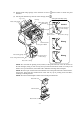
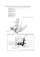
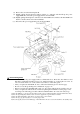
(8) Remove the screw from the FG plate R.
(9) Slightly pull up the FG plate R, pull two latches "a" outwards, and then lift up the power
supply PCB. Disconnect the power supply harness from the PCB.
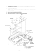
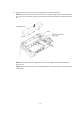
(10) Slightly pull up the FG plate L and release the main PCB from it. Release the NCU PCB from
latch "b" and disconnect it from the main PCB.
(11) Disconnect the power supply harness from the main PCB.
Reassembling Notes
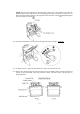
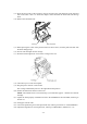
• Be sure to route the power supply harness as illustrated above. Route the other harnesses and
flat cables as illustrated in Subsection 4.1.22, "Harness Routing A." At the right rear corner, be
sure to hook the ferrite core of the scanner motor harness on the cable guide.
• After you replace the main PCB, be sure to follow the flowchart given on the next page.
• Be sure to route the grounding wire as illustrated on page 4-12.
• When you replace the main PCB with a new one, also replace ink absorber box with a new one.
• After you replace the ink absorber box without replacing the main PCB, reset the purge count
according to the following procedure. Otherwise, Machine Error 46 occurs at an early stage.
1) Press the [Menu], [*], [2], [8], [6] and [4] keys in this order to make the machine enter the maintenance mode.
2) Press the [8] and [0] keys in this order to show the equipment’s log information on LCD.
3) Press the [Fax Start] button nine times to show the purge count on LCD.
4) Press the [2], [7], [8] and [3] keys to reset the purge count.
5) Press the [9] key twice in the initial stage of the maintenance mode to restore the machine to the standby state.