
Service manual


VI-1
CHAPTER VI DIAGRAMS
1. PREFACE
1.1 How to Use the BSD
1. Enter the chain specified in the chapter of troubleshooting.
2. See the contents to enter the appropriate Chain.
3. Diagnose the failure in the appropriate Chain.
4. If the failure can be isolated, refer to the Parts List No or Adjustment No go to
the index of parts or the appropriate adjustment.
WARNING
Perform installation and removal of parts with the main power switch turned off and
the power cord unplugged to avoid electric shock and injury.
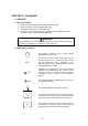
1.2 Explanations of Symbols
1
This symbol is used to refer to Notes usually
described in the same page.
PL7.7
This symbol is used to refer to the Parts List. PL
stands for Parts List; 7.7 denote Plate No. It shows
that the appropriate part is described in the
designated plate. This symbol is added to all the
exchangeable parts on BSD.
7.7.1
Reference to adjustments in the Service Manual
Section4 will be indicated by this symbol. In this
case, the number 7.7.1 indicate that the Adjustment
Procedure is found in ADJ 7.7.1 of the Service
Manual.
VR3
This symbol identifies a variable resistor, which can
be adjusted in the field.
TP
This symbol identifies a test point of a signal.
1.3
This symbol is used to show the location from where
the input to the Function comes. It shows that the
input comes from the Group Functions in Chain1-3.
6.1
This symbol is used to show the location where the
output from the Functions goes. It shows that the
output goes to the Group functions in Chain6-1.