
Service manual


HL-5030/5040/5050/5070N SERVICE MANUAL
3-17
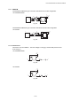
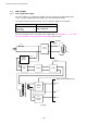
1.4 Engine PCB
The gate array which transforms the serial signal from the main PCB into the parallel signal is
mounted on the engine PCB.
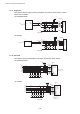
The engine PCB controls the following parts by using the transferred signal data;
• Main motor
• Solenoid
• Fan motor
• Upper cassette sensor
• Thermistor
• Lower cassette sensor
• Polygon motor • Upper paper exit sensor
• High-voltage power supply • Lower paper exit sensor
• Toner sensor • Lower cassette exit sensor
• Cover sensor • Paper eject sensor
• Front registration sensor • Fixing unit cover sensor
• Rear registration sensor • Multi-purpose tray paper exit sensor
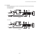
For the circuit diagram of the engine PCB, see APPENDIX 9. and 10. ‘ENGINE PCB CIRCUIT
DIAGRAM’ in this manual.
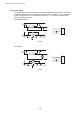
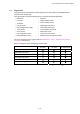
Sensor configuration varies according to machine types.
HL-5030 HL-5040 HL-5050/5070N
Upper cassette sensor
Upper paper exit sensor
Lower cassette sensor
Lower paper exit sensor
Lower cassette exit sensor
Multi-purpose tray paper exit sensor
: Built-in : Not built-in