LK3-B448E / BA-16 INSTRUCTION MANUAL Please read this manual before using the machine. Please keep this manual within easy reach for quick reference.
Thank you very much for buying a BROTHER sewing machine. Before using your new machine, please read the safety instructions below and the explanations given in the instruction manual. With industrial sewing machines, it is normal to carry out work while positioned directly in front of moving parts such as the needle and thread take-up lever, and consequently there is always a danger of injury that can be caused by these parts.
DANGER Wait at least 5 minutes after turning off the power switch and disconnecting the power cord from the wall outlet before opening the face plate of the control box. Touching areas where high voltages are present can result in severe injury. CAUTION Environmental requirements Use the sewing machine in an area which is free from sources of strong electrical noise such as highfrequency welders. Sources of strong electrical noise may cause problems with correct operation.
CAUTION Sewing This sewing machine should only be used by operators who have received the necessary training in safe use beforehand. If using a work table which has casters, the casters should be secured in such a way so that they cannot move. The sewing machine should not be used for any applications other than sewing. Attach all safety devices before using the sewing machine. If the machine is used without these devices attached, injury may result.
Warning labels c ★ The following warning labels appear on the sewing machine. Please follow the instructions on the labels at all times when using the machine. If the labels have been removed or are difficult to read, please contact your nearest Brother dealer. 1 Hazardous voltage will cause injury. Turn off main switch and wait 5 minutes before opening this cover. 2 Hochspannung verletzungsgefahr! Bitte schalten sie den hauptschalter aus und warten sie 5 minuten, bevor sie diese abdeckung ffnen.
CONTENTS 1. Name of each part ................................................................................................................. 2. Specifications .......................................................................................................................... 1 2 2-1. Specifications .............................................................................................................................. 2 2-2. Program list ......................................................
8. Sewing ......................................................................................................................................... 33 9. Maintenance and inspection .......................................................................................... 34 9-1. Cleaning the rotary hook ........................................................................................................... 9-2. Cleaning the control box air inlet port ......................................................
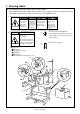
1.Name of each part 1.
2. Specifications 2. Specifications 2-1. Specifications Stitch formation Maximum sewing speed Maximum pattern size Needle Dimensions of buttons that can be sewn Button clamp height Thread knot Feed mechanism Stitch length Number of stitches Single needle lock stitch 2,500 rpm 0 - 6.4 ✕ 0 - 6.4 mm TQ ✕ 1#12 Outer diameter of button 9 - 22 mm Space between the button holes 2.5 - 6.4 mm 10 mm (standard) Knot tied by needle R-θ intermittent feed mechanism (pulse-motor driven mechanism) 0.1 - 6.
2. Specifications 2-2. Program list Sewing patterns are limited as shown in the table below. (Any program is available as long as the needle drops down in the hole of the button.) Program No. No. of button holes Sewing pattern No. of threads No. of crossover stitches No.
2. Specifications No. of threads No. of crossover stitches 16 6-5 1 19 17 8-7 1 23 30 10-9 1 27 6-6 1 20 8-8 1 24 10-10 1 28 12-12 1 32 6-6 0 26 8-8 0 30 10-10 0 34 6-6 1 20 10-10 1 28 6-6 0 26 35 10-10 0 34 46 6-6 1 20 47 8-8 1 24 Program No. 18 19 31 45 20 32 33 21 34 No. of button holes *2 *2 *2 *2 *3 *3 *3 *2 *2 *2*3 22 *2*3 Sewing pattern No. of Standard Standard stitches sewing length X sewing width Y 3.4mm 3.4mm 2.4mm 3.4mm 3.4mm 3.
2. Specifications No. of threads No. of crossover stitches 36 6-6 0 26 37 8-8 0 30 38 10-10 0 34 39 12-12 0 38 6-6 0 26 41 8-8 0 30 42 10-10 0 34 6-6 0 26 No. of Program No. button holes 4 40 43 44 Sewing pattern * * 10-10 0 No. of Standard Standard stitches sewing length X sewing width Y 3.4mm 3.4mm 2.4mm 3.4mm 34 *2 Do not use the button lifter spring.
2. Specifications 2-3. Optional parts ■ Liquid cooling tank This helps to prevent thread breakages caused by friction when using synthetic threads. Fill the tank with silicone oil (100 mm2/s). ■ Two-pedal foot switch The switch has an independent presser switch (left side) and start switch (right side). ■ Solenoid-type thread wiper When sewing without crossover threads (program Nos 14, 15, 20 and 22, 28, 29 and 32, 33, 35), do not move the button clamp assembly vertically while sewing is in pro-gress.
3. Installation 3. Installation CAUTION Machine installation should only be carried out by a qualified technician. result in personal injury or damage to the machine. Contact your Brother dealer or a qualified electrician for any electrical work that may need to be done. All cords should be secured at least 25 mm away from any moving parts. Furthermore, do not excessively bend the cable or secure it too firmly staples, otherwise there is the danger that fire or electric shocks could occur.
3. Installation 3-2. Installing the motor Install the motor u to the work table with the four accessory bolts q, cushions w, cushion collars e, flat washers r, spring washers t and nuts y. At that time, fix by setting bolts q a little to the right of oval hole on motor. NOTE: Tighten the nuts so that the clearance between the table and the cushion collars is approximately 1 mm. Table 1 mm 3-3.
3. Installation 3-4. Installing the control box Table Cushions Cushion collars 3 mm Rubber collars Flat washers Nuts 1. Remove the 12 screws q, and then open the covers (panel mounting assembly w and main P.C. board mounting plate e). NOTE: When opening the cover, hold it securely so that it does not fall down. 2. Install the control box with the four accessory bolts r, cushions t, cushion collars y, rubber collars u, flat washers i and nuts o as shown in the illustration above.
3. Installation 3-5. Installing the oil pan 1. Insert the tabs of the oil pan w into the holes for the cushions q, and then secure it in place with the five nails e so that the oil pan w is not at an angle. 2. While pushing the oil pan w down from above, screw in the oil container r. 3-6. Installing the cushions e w 1. Place the washers q and cushions w into the two holes in the work table. * Adjust the height of the machine head to the button feeder by the number of the washers q. 2.
3. Installation 3-7. Installing the machine head 1. Insert the two hinge assemblies q into the machine head so that they are parallel, and then secure them with the two set screw w. w q 2. Place the machine head gently on the table. NOTE: Pull the cords e out as shown in the illustration above in order to prevent them from being clamped by the machine head. 1 mm 3. Secure the two hinge assemblies q with the washers r, the spring washers t, and the bolts y, and install the machine head. e r t y 3-8.
3. Installation 3-9. Installing the liquid cooling tank, optional 1. Remove the rubber plug, and then push the liquid cooling tank q. 2. Tighten it with the set screw w. 3-10. Installing the vibrating bowl 1. Install the vibration bowl q with bolts w, spring washers e, and washers r. 2. Pass the wires from the vibration bowl q through the hole in the table. 3-11. Installing the control box (for vibrating bowl) 1. Mount the control box q to the bottom of the box stay e with screws w. 2.
3. Installation 3-12. Installing the button feeder 1. Move button feeder base q to the front and rear and left and right as necessary to install it by using hole bolts w, spring washers e and washers r. (And install ground wires ty.) To vibrating bowl To control box (For vibrating bowl) 3-13. Installing the shooter 1. Raise the shooter lock pin w on the vibrating bowl q, and secure the shooter e by inserting the pin w, through the notch in the shooter. 2.
3. Installation 3-14. Connecting the cords P8 P1 P2 P3 P4 P5 P6 P7 P11 Machine head connectors Connection location Connection location on circuit board No.
3. Installation ■ Button feeder connection Pull on the connector to make sure it will not come disconnected after connecting the pins.
3. Installation ■ Power switch connection Power switch connector (control box) Control box (for vibrating bowl) Green/Yerrow Black White Red B A Control box side A Green/Yerrow Black White Red Control box side B Green/Yerrow Red White 3-15. Installing the button feeder cover Attach the button feeder cover q to the button feeder w with screws e, spring washers r, and washers t. * Be sure to pass the wires through the hole in the cover when attaching the button feeder cover q.
3. Installation 3-16. Installing the operation panel The operation panel can be installed to either the top or bottom of the work table. r e w q 1. Install the operation panel presser plate q to the top of the button feeder cover with the two screws w. 2. Insert the panel e into the operation panel presser plate q, and then secure it with the two screws r. 3. Insert the connector cord t into the control box through the hole at the side of the box. Refer to “3-13.
3. Installation 3-18. Installing the V-belt Approx. 1 mm Approx. 9 - 10 mm 10 N 1. Gently tilt back the machine head, and then place the V-belt q into the V grooves on the machine head pulley w and the motor pulley e. NOTE: After tilting back the machine head, do not push the face plate side or the pulley side from above. 2. Gently return the machine head to its original position. * Be careful not to clamp the cords at this time. 3.
3. Installation 3-19. Installing the belt cover w q e t u r y 1. Loosen the two screws w of the upper cover q and the two screws r of bed cover L e. 2. Insert the belt cover t in the direction of the arrow, and then secure it with the two screws w. * When tilting back the machine head, loosen the screws w and r, remove the screw y and then remove the belt cover t first. 3. Attach the rubber plug u to the belt cover. 3-20.
3. Installation 3-21 . Installing the motor cover q w r 1. Install the motor cover q to the motor back cover w with the screws e and the flat washers r. 2. Pass the motor shaft through the notch in the motor back cover w, and then tighten the screws y and the washers u so that the clearance between the motor pulley t and the motor cover q is uniform. e u y t 3-22 .
3. Installation 3-24. Adjustment by the accessory spring If you would like the button to be raised up more after it is sewn, install the accessory spring. w q e r t 1. Install the spring support q with the bolt w. 2. Install the spring e with the washer r and the screw t.
4. Lubrication 4. Lubrication CAUTION Turn off the power switch before starting lubricating, otherwise the machine may operate if the foot switch is depressed by mistake, which could result in injury. Be sure to wear protective goggles and gloves when handling the lubricating oil and grease, so that they do not get into your eyes or onto your skin, otherwise inflammation can result. Furthermore, do not drink the oil or eat the grease under any circumstances, as they can cause vomiting and diarrhoea.
4. Lubrication 4-2. Applying grease Do not apply too much grease in the place indicated by the arrow. If too much grease is applied here, the button clamp may not move up and down smoothly and error [E-6 ] may appear on the display. 4-3. Draining the oil 1. Remove and empty the waste oil container q whenever it is full. 2. After emptying the waste oil container q, screw it back into its original position.
5. Operation 5 . Operation 5-1 . Name and function of each operation panel item u q P POWER w RESET i o Y-SCALE P2 P3 P4 SPEED r TEST P1 X-SCALE !0 e PROGRAM NO. !4 !1 COUNTER t BOBBIN.WIND SELECT y q POWER indicator ................... Illuminates when the power switch has been turned on. w RESET switch ........................ Press this switch to reset the machine when an error occurs. e TEST switch ...........................
5. Operation P POWER RESET i BOBBIN.WIND P1 P2 !3 X-SCALE o Y-SCALE !0 TEST PROGRAM NO. P3 P4 SPEED !4 !1 COUNTER SELECT !2 y i X-SCALE indicator ................. Illuminates when the SELECT switch y is pressed to shown the X-scale setting. o Y-SCALE indicator ................. Illuminates when the SELECT switch y is pressed to shown the Y-scale setting. !0 SPEED indicator .................... Illuminates when the SELECT switch y is pressed to shown the speed setting.
5. Operation 5-2 . Operating procedure NOTE: Be sure to check the sewing pattern (refer to page 20) after setting has been completed to make sure that the needle drops down into the hole of the button. Preparation Turn on the power switch. (The POWER indicator q will illuminate and the program number will flash in the display window !4.4 ) Factory default Variable range Program No.
5. Operation 5-3. Operating the button feeder AUTO 1 OFF q q AUTO 2 e w w BA-1 6 1. Button feeder switch q AUTO1 ... Buttons are supplied automatically after sewing is complete. AUTO2 ... When sewing is complete and the button clamp releases its button, the next button is supplied. OFF ........ Buttons are not supplied automatically. 2. Trouble indicator w (1) When buttons are being fed to the button clamp, the trouble indicator w will be OFF.
6. Checking the sewing pattern 6. Checking the sewing pattern ■ When checking by operating only the feed mechanism 1. Turn on the power switch. (The POWER indicator will illuminate and the program number will flash in the display window.) 2. Depress the foot switch to the second step. (After the home position is detected, the button clamp will rise.) 3. Set the button. (Press the MANUAL switch on the button feeder.) 4.
7. Correct use 7. Correct use 7-1 . Selecting the needle and thread Needle Thread Refer to the table at right for details on which needle and thread to select. TQ × 1 #11 NOTE: Use buttons which have a hole diameter that is greater than the value given in the table, to ensure that the needle does not touch the button. TQ × 1 #14 TQ × 1 #12 #60 #50 Button hole diameter 1.5mm or greater 1.6mm or greater 1.7mm or greater 7-2 .
7. Correct use 7-4 . Winding the lower thread CAUTION Do not touch or place anything against any of the moving parts while winding the lower thread, otherwise personal injury or damage to the machine may result. 1. Place the bobbin all the way onto the shaft. 2. Thread the thread as shown in the illustration at right, wind the thread around the bobbin several times in the direction of the arrow, and then press the bobbin presser q. q 3. Turn on the power switch.
7. Correct use 7-5. Replacing the bobbin case and threading the thread CAUTION Turn off the power switch before removing and replacing the bobbin case, otherwise the machine may operate if the foot switch is depressed by mistake and serious injury could result. w r e 30mm q Pull the shuttle race cover q toward Insert a new bobbin into the bobbin Pass the thread through the lever you to open it.
7. Correct use 7-6-3 . Thread take-up spring height Lower 7-6-4. Thread take-up spring tension Higher q q Loosen the set screw q and turn the tensioner body to adjust the thread take-up spring height. Stronger Weaker Turn the tension stud q with a screwdriver. 7-6-5. Adjusting arm thread guide R Become greater A Become less q The standard position of arm thread guide R q is when the screw w is aligned with mark A. To adjust the position, loosen the screw w and then move arm thread guide R q.
8. Sewing 8. Sewing CAUTION Turn off the power switch at the following times, otherwise the machine may operate if the foot switch is depressed by mistake, which could result in injury. • Threading • When replacing the bobbin and needle • When not using the machine and when leaving the machine unattended Do not touch any of the moving parts or press any objects against the machine while sewing, as this may result in personal injury or damage to the machine. Before starting sewing...
9. Maintenance and inspection 9. Maintenance and inspection CAUTION Turn off the power switch before starting any cleaning work, otherwise the machine may operate if the foot switch is depressed by mistake, which could result in injury. Be sure to wear protective goggles and gloves when handling the lubricating oil and grease, so that they do not get into your eyes or onto your skin, otherwise inflammation can result.
9. Maintenance and inspection 9-3. Cleaning the eye guard Wipe the eye guard clean with a soft cloth. NOTE: Do not use solvents such as kerosene or thinner to clean the eye guard. 9-4. Checking the needle Always check that the tip of the needle is not broken and also the needle is not bent before starting sewing.
10. Adjustments 10 . Adjustments CAUTION Maintenance and inspection of the sewing machine should only be carried out by a qualified technician. Ask your Brother dealer or a qualified electrician to carry out any maintenance and inspection of the electrical system. Turn off the power switch and disconnect the power cord from the wall outlet at the following times, otherwise the machine may operate if the foot switch is depressed by mistake, which could result in injury.
10. Adjustments 10-1 . Adjusting the needle bar height q w e A Turn the machine pulley to move the needle bar to the lowest position. Then remove the rubber plug w, loosen the set screw e and then move the needle bar up or down to adjust so that the highest reference line (reference line A) is aligned with the lower edge of the needle bar bush q. 10-2 .
10. Adjustments 10-3 . Adjusting the driver needle guard Needle center line Tip r e e w Turn the machine pulley to align the tip of the rotary hook with the needle center line. Then loosen the set screw w and turn the eccentric shaft e to adjust so that the driver needle guard q contacts the needle. If the needle contact pressure is too great, skipped stitches may occur.
10. Adjustments 10-6.Adjusting the thread take-up amount q Thread take-up amount (stroke) e Become less Become greater w q r At the time of shipment from the factory, the thread take-up amount (stroke) of the thread take-up lever q is set to the standard setting of 5 mm. You may need to adjust this setting depending on the sewing conditions to prevent the thread from pulling out at the sewing start. [Adjustment method] Loosen the screw w and move the stopper (3.
10. Adjustments 10-7-1. Replacing the movable knife and fixed knife q q t w r t e u y 1. Open the large shuttle hook cover, remove the screw q, and then remove the feed plate w. 2. Remove the two screws e and the two screws r, and then remove the needle plate t. 3. Remove the thread trimmer connecting rod y from the connecting rod lever pin u. i !1 !0 o 0.5 mm o 4. Remove the movable knife i and replace it with a new one.
10. Adjustments 10-7-2. Adjusting the engagement of the movable knife and fixed knife Fig. 1 B A C Movable knife D Cutting edge Fix knife Cutting edge Cutting edge Cutting edge A. After the movable knife and fixed knife are properly engaged, tighten the screw as shown in Fig.1. B. Turn the movable knife (in the direction of the arrow) while the screw is still tightened. C. Loosen the screw. D. Turn the movable knife (in the direction of the arrow) while the screw is still loosened.
10. Adjustment 10-9. Adjusting the holding pressure Loosen screw q and turn adjustment screw w so that clamp pressure is as light as possible but high enough so that the material will not slip when pulled lightly. * If the clamp pressure is too high, the buttons may not be fed properly. w q 10-10. Adjusting the position of the button holder 1. Loosen the two hexagonal bolts q and adjust the button holder body w by moving it. 2. Check that the needle will go through the button hole with no contact.
10. Adjustment 10-11. Adjusting the button clamp height Surface A Button Button guide surface Flush Adjustment 1. After turning on the power switch, turn AUTO 1 or AUTO 2 the feeder switch. 2. The button carrier will move slowly if the foot switch is turned on with the manual switch depressed. The sewing machine will operate in inching mode while the manual switch is being pressed, and will stop when the manual switch is released. 3.
10. Adjustment 10-12. Adjusting the needle up stop position The needle up stop position is adjusted so that the index mark w on the machine pulley q is inside the mark r on the belt cover e. If adjustment is necessary, loosen the screw t at the “U” mark of the machine pulley q and adjust the position of the machine pulley q. The machine pulley q stops later if it is turned clockwise, and it stops earlier if it is turned counterclockwise.
10. Adjustment 10-14. Adjusting the vibrating bowl Gap for double row of buttons The vibrating bowl arranges all of the buttons face up and feeds the buttons to the shooter. Be sure to readjust the vibrating bowl whenever the buttons are changed. ■ If buttons are not fed properly, check the following. 1. Loosen screw w and adjust the gap between the bottom of arm B q and the vibrating bowl so that two buttons can pass. 2.
10. Adjustment 10-15. Adjustment for excess buttons in the button shooter 1. Turn the button carrier q by hand in the direction of the arrow, and remove any buttons from the button carrier pin w. 2. With the button carrier q in this position, pull lever e to remove any excess buttons from the shooter at point A. 3. Press the manual switch to feed a button to the button clamp.
10. Adjustment 10-16. Button replacement 10-16-1. Adjustment when the button diameter is changed ■ Slide base adjustment 1. Adjust the width of the slide base assembly w to the button width with slide base screw e so that the bottons q pass smoothly. The bed slide base assembly w can be adjusted for button diameters of 9 to 22 mm. Adjust so that the clearance between the buttons q and the edge of the slide base assembly w is 0.5-1.0 mm. 2. There are 3 different button upper covers r.
10. Adjustment 10-16-2. Adjustment when the button thickness changes Thickness Spacer 1. Check to be sure that buttons q are being smoothly sent to the shooter w. If the buttons are not fed smoothly, replace the shooter. 2. Install accessory spacers (0.4 mm, 0.8 mm, ) as required by the button thickness. 3. Check to be sure that buttons are being securely grasped by the button clamp. * If no spacers are used, button thicknesses from 1.8 to 2.2 mm can be used. 10-16-3.
10. Adjustment 10-16-5. Adjusting the feeder position adjustment * For all programs, the shunting point for the sewing home position point is set to the first stitch position. As long as the button size is not changed, it is not necessary to change the program in order to adjust the feeder position. AUTO 1 OFF q AUTO 2 L-R F-B w BA-1 6 Two holes Four holes 1. Turn on the power switch. 2. Check whether or not the feeder switch q is AUTO 1. 3.
10. Adjustment 10-16-6. Adjusting the needle location Adjustment is required whenever the button carrier is replaced. Make sure the needle is not bent. ■ Horizontal feed position A B Button hole gap Horizontal feed Needle 1. Set the X scale so that the holes A and B in the button are aligned with the point of the needle. (Refer to “Setting the X-scale and Y-scale” on page 45.) 2. Check the positions of the button holes. (Refer to “Checking the sewing pattern” on page 26.
10. Adjustment 10-17. Replacement the V-belt r q e w 1. Then remove the belt cover. (Refer to “Tilting back the machine head” on page 35). 2. Remove the motor back cover q with the screws w and the flat washers e. 3. Remove the wood screw t and washers y securing the motor cover r, and remove the table. y t 4. Gently tilt back the machine head, and then place the V-belt u remove the V grooves on the machine head pulley i and the motor pulley o.
10. Adjustment Sewing machine V-belt NOTE: Use brother specified V-belt (belt, VM). The V-belt may stretch slightly when it is first used, so adjust the belt tension after about 3,000 cycles of use. When above belt tension is weak, this will be cause of following problems; • Noise and vibration become large. • Needle up stop position becomes unstable. • Error message [E-5] is displayed. Check that the motor is positioned so that the V-belt is straight. (Fig.1) Motor Fig.
10. Adjustment 10-18. Checking the input sensor and DIP switch input POWER q P PROGRAM NO. P1 P2 P3 P4 X-SCALE e RESET Y-SCALE SPEED w TEST BOBBIN.WIND r COUNTER SELECT t 1. When the X-SCALE indicator q is illuminated and the RESET switch e is pressed while the TEST switch w is being pressed, the state of the X home position signal will appear on the display window r. · When sensor is ON · When sensor is OFF 2.
10. Adjustment 10-19. Checking the input voltage P PROGRAM NO. POWER P1 P2 P3 P4 X-SCALE r w RESET Y-SCALE SPEED e TEST t COUNTER BOBBIN.WIND SELECT q Specifications Display 200V [090 - 110] 220V [100 - 120] 230V [105 - 125] 100V 380V 400V 415V [100 - 120] Notes “100” is displayed when the input voltage is 200 V. “110” is displayed when the input voltage is 100V (for 100-V spece.), 380V (for 380-V spece.), 400V (for 400-V spece.)or 415V (for 415-V spece.). 1. 2. 3. 4.
10. Adjustment 10-20. Moving stitch patterns • Programs which have already been programmed can be moved up, down and to the left and right. (However, such patterns will be reset if the power supply is turned off or the program number is changed.) • The feed position can be set to the any position desired. w u i r t e y BOBBIN.WIND SELECT q o 1. Select the program number, and then press the start switch once to move the feed mechanism to the sewing start position. 2.
11. Using the counters 11.Using the counters 11-1 . Using the bobbin thread counter If you use the bobbin thread counter to set the number of articles which can be sewn with the amount of bobbin thread available, you can stop the bobbin thread running out in the middle of sewing a pattern. r e w q y t 1. Press the SELECT switch q until the COUNTER indicator w illuminates. 2. While pressing the TEST switch e, press the RESET switch r.
12. Using user programs 12.Using user programs User program ... It can store sixteen different programs which can include details such as the program number, X scale, Y scale and sewing speed. If you are sewing certain patterns over and aver again, it is useful to record the settings for these patterns into a user program. Recording a user program 1. Turn off the power switch and then set DIP switch A3 of the DIP switches q to ON. !1 P PROGRAM NO. POWER P1 P2 P3 P4 X-SCALE 2.
12. Using user programs Using a user program 1. Press the DISPLAY SET switches !0 to select the speed program number for the user program that you would like to use. *The user program numbers P1 to P4 can also be selected using the user program switches !1. 2. Depress the foot switch to the second step. 3. Check the sewing pattern (see P.20), and then sew the pattern selected. Clearing the user programs 1. Switch the machine to recording mode by the procedure in steps 2. of recording a user program. 2.
13. Using the cycle sewing function 13. Using the cycle sewing function What is the cycle sewing function? The cycle sewing function lets you program up to four patterns for cycle sewing of patterns in a predeter mined order. Recording a cycle sewing program q 1. Set DIP switch q-3 to ON, and then record the patterns which you would like to use for cycle sewing. (Refer to “12-4. Using user programs”.) * Cycle sewing cannot be performed using patterns (P1 to P16) which have not had a user program assigned.
13. Using the cycle sewing function Using a cycle sewing program 1. When “c1-1” is flashing in the display window !0, press the foot switch to the second step. 2. Start sewing. 3. “c1-1”, “c1-2”, “c1-3” are sewn in order for each article, and when the last-recorded pattern has been sewn, the display returns to “c1-1”. * If you press one of the DISPLAY SET switches !1 when “c1-*” is displayed, you can return to the previous stitch pattern or skip a stitch pattern.
14. Changing functions using the DIP switches 14. Changing functions using the DIP switches 14-1. Operation panel DIP switches The operation panel DIP switches q are used to change functions which might need to be changed depending on the sewing conditions. NOTE: Always turn off the power before setting the DIP switches. The functions shown in the table below can be changed by means of these DIP switches. * All DIP switches are set to OFF at the time of shipment.
14. Changing functions using the DIP switches 14-3 . DIP switches inside the control box DANGER Wait at least 5 minutes after turning off the power switch and disconnecting the power cord from the wall outlet before opening the face plate of the control box. Touching areas where high voltages are present can result in severe injury. The DIP switches q inside the control box are used to change functions which do not often need to be changed once they have been set.
15. Changing special functions using the memory switches 15. Changing special functions using the memory switches The functions of the switches on the operation panel q can be changed to carry out special functions. NOTE: After changing the memory switch settings, press the power switch to turn the power off and then back on again. The memory switches “00 - 2F” (except “08”) are set to OFF at the time of shipment. 1. Turn on the power switch. 2. While pressing the TEST switch w, press the BOBBIN.
15. Changing special functions using the memory switches ■ Memory switches 10 - 1F Motion when set to ON Switch memo-10 The optional emergency stop switch can be used. memo-11 - memo-13 — memo-14 Solenoid wiper can be used (available as an option). memo-15 — memo-16 Needle cooler output is enabled. (Needle cooler is available by special order.) memo-17 Thread take-up device is not operated at the sewing end. memo-18 Thread take-up device operates one stitch before the sewing end.
16. Table of error codes 16. Table of error codes DANGER Wait at least 5 minutes after turning off the power switch and disconnecting the power cord from the wall outlet before opening the face plate of the control box. Touching areas where high voltages are present can result in severe injury. If a malfunction should occur with the sewing machine, a buzzer will sound and an error code will appear in the display window. Follow the remedy procedure to eliminate the cause of the problem.
16. Table of error codes Code Remedy Cause E-A0 Home position cannot be detected (malfunction of home position sensor), or malfunction of power supply circuit board. Turn off the power and check the connection of home position sensor connector P1. E-b0 You tried to change the program number when DIP switch A-8 was set to ON. Press the RESET switch. Set DIP switch A-8 to OFF before trying to change the program number.
17. Adjustment guide refer to this guide when different button are used 17.
18. Troubleshooting 18. Troubleshooting Problem Cause Check Remedy Page Button clamp lifter amount is too great. Distance between button clamp and top of needle plate Adjust the height of the button clamp to within 13 mm. 46 Presser is contacting thread wiper. Thread wiper standby position Adjust the position of the thread wiper. 48 Button clamp does not drop. Presser lifter link is not moving back. Link return spring is unhooked. Hook the link return spring properly.
18. Troubleshooting Problem Upper thread breaks. Cause Check Skipped stitches occur. Page Upper thread tension is too strong. Upper thread tension Adjust the upper thread tension. 27 Needle is installed incorrectly. Needle direction Install the needle so that the groove is facing forward. 27 Thread is too thick for the needle. Thread and needle Use the correct thread for the needle. 27 Thread takeup spring tension and height Adjust the tension and height of the thread takeup spring.
18. Troubleshooting Problem Cause Check Sharpen or replace the fixed knife. Shuttle race thread guide position Adjust the position of the shuttle race thread guide. 43 Needle bar lift amount Adjust the needle bar lift amount. 41 The movable knife does not pick up the thread because of skipped stitches at the sewing end. Skipped stitches at sewing end Refer to "Skipped stitches occur". Movable knife position is incorrect. Movable knife position Adjust the position of the movable knife.
INSTRUCTION MANUAL BROTHER INDUSTRIES, LTD. 15-1, Naeshiro-cho, Mizuho-ku, Nagoya 467-8561, Japan. Phone: 81-52-824-2177 Printed in Japan 151-916 S93V48-002 2000.06.