
Instruction manual

9. STANDARD ADJUSTMENTS
48
KE-436C
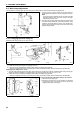
9-15. Checking the input sensor and DIP switch input
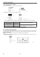
1. When the SPLIT NO. indicator (1) is illuminated and the R/W switch (3) is pressed while the TEST switch (2) is being
pressed, the X-SCALE indicator (4) will illuminate and the state of the X home position signal will appear on the display
screen (5).
When sensor is ON When sensor is OFF
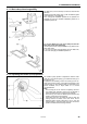
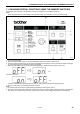
2. Each time the MENU switch (6) is pressed, a different indicator will illuminate and the operating condition for the
corresponding item will appear on the display screen (5).
• When X-SCALE indicator is illuminated : X home position sensor
• When Y-SCALE indicator is illuminated : Y home position sensor
• When SPEED indicator is illuminated : Needle up signal (synchronizer)
• When B.T. COUNTER indicator is illuminated : 24-section signal (synchronizer)
• When SPLIT ON. indicator is illuminated : Needle down signal (synchronizer)
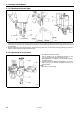
3. If the settings for DIP switch A at the side of the operation panel are changed at this time, the number of theˇychanged switch
will appear in the top row of the program number display (7).
4. If the settings for DIP switch B are changed at this time, the number of the changed switch will appear in the bottom row of
the program number display (7).
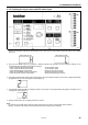
5. Press the TEST switch (2). The display will return to normal.
Note:
You need to move the DIP switch while the power is still turned on in order to check the DIP switch operation.
However, the power must always be turned off before DIP switch settings can be changed.
2729Q