BAS-300G BAS-311G BAS-326G Basic Operation Manual DIRECT DRIVE PROGRAMMABLE ELECTRONIC PATTERN SEWER Please read this manual before using the machine. Please keep this manual within easy reach for quick reference. This basic operation manual describes basic operations including sewing machine operations. For cleaning, standard adjustments and more details, please refer to the instruction manual contained in the Document CD.
Thank you very much for buying a BROTHER sewing machine. Before using your new machine, please read the safety instructions below and the explanations given in the instruction manual. With industrial sewing machines, it is normal to carry out work while positioned directly in front of moving parts such as the needle and thread take-up lever, and consequently there is always a danger of injury that can be caused by these parts.
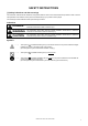
SAFETY INSTRUCTIONS [1] Safety indications and their meanings This instruction manual and the indications and symbols that are used on the machine itself are provided in order to ensure safe operation of this machine and to prevent accidents and injury to yourself or other people. The meanings of these indications and symbols are given below. Indications DANGER The instructions which follow this term indicate situations where failure to follow the instructions will result in death or serious injury.
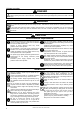
[2] Notes on safety DANGER Wait at least 5 minutes after turning off the power switch and disconnecting the power cord from the wall outlet before opening the cover of the control box. Touching areas where high voltages are present can result in severe injury. WARNING Do not allow any liquids to get onto this sewing machine, otherwise fire, electric shocks or operating problems may occur.
CAUTION Sewing This sewing machine should only be used by operators who have received the necessary training in safe use beforehand. If using a work table which has casters, the casters should be secured in such a way so that they cannot move. The sewing machine should not be used for any applications other than sewing. Attach all safety devices before using the sewing machine. If the machine is used without these devices attached, injury may result.
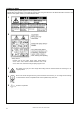
[3] Warning labels The following warning labels appear on the sewing machine. Please follow the instructions on the labels at all times when using the machine. If the labels have been removed or are difficult to read, please contact your nearest Brother dealer. 1 2 .
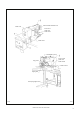
Tension release solenoid cover Motor cover Inner cover L Outer cover Fixed cover L Motor cover L Thread take-up cover Inner cover R Eye guard Outer cover Fixed cover R Motor cover R Finger guard Gas spring support cover 2960B 2961B BAS-300G, BAS-311G, BAS-326G v
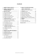
CONTENTS 1. NAMES OF MAJOR PARTS ................ 1 2. USEFUL FUNCTIONS FOR OPTIMUM SEWING .............................. 2 3. INSTALLATION .................................... 3 3-1. Table processing diagram ................................ 4 3-2. Installing the control box................................... 5 3-3. Installing the oil pan.......................................... 5 3-4. Installing the machine head.............................. 6 3-5. Tilting the sewing machine head ......................
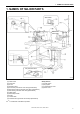
1. NAMES OF MAJOR PARTS 1.
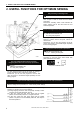
2. USEFUL FUNCTIONS FOR OPTIMUM SEWING 2. USEFUL FUNCTIONS FOR OPTIMUM SEWING Easy threading in threading mode Page 20 When using threading mode for threading, the tension discs will open so that the thread can be threaded more easily. Furthermore, threading mode is safe because the sewing machine will not start even when the foot switch is depressed. Presser foot height can be set easily using the panel Page 30 INSTRUCTION MANUAL CD 6-7.
3. INSTALLATION 3. INSTALLATION CAUTION Machine installation should only be carried out by a qualified technician. Contact your Brother dealer or a qualified electrician for any electrical work that may need to be done. The sewing machine head weighs approximately 88kg. The installation should be carried out by two or more people. Do not connect the power cord until installation is complete. If the foot switch is depressed by mistake, the sewing machine might start operating and injury could result.
3. INSTALLATION 3-1. Table processing diagram • The thickness of the table should be at least 40 mm, and it should be strong enough to bear the weight and vibration of the sewing machine. • If the distance A between the insides of the legs is less than 740 mm, move the control box installation position to the left (B = 261mm). • Check that the control box is at least 10 mm away from the leg. If the control box and the leg are too close together, it may result in incorrect sewing machine operation.
3. INSTALLATION 3-2. Installing the control box Remove the eight screws (1), and then remove the control box cover (2). (3) Control box (4) Bolts [4 pcs.] (5) Plain washers [4 pcs.] (6) Spring washers [4 pcs.] (7) Nuts [8 pcs.] 1840B (8) Power switch (9) Wood screws [2 pcs.] (10) Staples [4 pcs.] Operator 1841B 3-3. Installing the oil pan For motor-driven work clamp specifications, install the treadle unit mounting bolt (A) before installing the oil pan. (Refer to "3-7.
3. INSTALLATION 3-4. Installing the machine head (1) Pins [2 pcs.] (2) Set screws [2 pcs.] (3) Hinge rubber assemblies [2 pcs.] Place the machine head gently on top of the oil pan and the rubber cushions. Pulse motor Approx. 20 mm NOTE: • Be careful not to get the cords clamped between the machine head and the oil pan. • When holding the machine head, do not hold it by the pulse motor. This may cause problems with operation of the pulse motor. Approx.
3. INSTALLATION 2698B (10) Auxiliary plate (11) Bolts with washer [4 pcs.] Loosen the four bolts with washer (11), and adjust so that the auxiliary plate (10) is 0 to 0.5 mm above the needle plate. Needle plate NOTE: Install the auxiliary plate (10) so that it is horizontal. If the auxiliary plate (10) is lower than the needle plate, the feed plate may get caught on the needle plate. (10) Auxiliary plate (11) Bolts with washer [10 pcs.
3. INSTALLATION Be sure to install so that the side with “UP” on it is facing upward. (13) Gas spring holders [2 pcs.] (14) Spacer (15) Bolt (16) Nut (17) Gas spring (18) Shaft collars [2 pcs.] (19) Gas spring shaft D (20) Plain washers [2 pcs.] (21) Retaining rings E [2 pcs.] (22) Bolts [2 pcs.] (23) Plain washers (medium) [2 pcs.] (24) Plain washers (large) [2 pcs.] (25) Spring washers [2 pcs.] (26) Nuts [2 pcs.
3. INSTALLATION Figure 1 Oil pan 2365B • Gently return the machine head to its original position. • Loosen the screw (31). Move the machine head switch (32) to the position shown in the illustration, and then secure the machine head switch (32) with the screw (31) and the accessory M3x16 screw (33). • Check that the machine head switch (32) is turned on as shown in figure 1. NOTE: If the machine head switch is not turned on, errors "E050", "E051" and "E055" will be generated. 3-5.
3. INSTALLATION 3-6. Installing the operation panel 2971B (1) (2) (3) (4) (5) Operation panel set Panel rubber Plain washers [6 pcs.] Bolts [3 pcs.] Nuts [6 pcs.] • Insert the cord from the operation panel (1) which has been passed through the hole in the table into the control box through the hole in the side of the control box. (6) Staples [3 pcs.] (1) (2) (3) (4) (5) (6) (7) Operation panel base Cushion A Plain washers (medium) [3 pcs.
3. INSTALLATION 3-7. Installing the treadle unit (motor-driven work clamp specifications) (1) (2) (3) (4) (5) Treadle unit Bolts [3 pcs.] Plain washers [3 pcs.] Spring washers [3 pcs.] Nuts [3 pcs.] NOTE: • Install the bolt for mounting hole A before installing the oil pan. (Refer to “3-3. Installing the oil pan.”) • Mounting hole B is used to install the gas spring supports with the bolt, plain washer, spring washer and nut. (Refer to "3-4. Installing the machine head".
3. INSTALLATION 3-9. Connecting the cords 1. Gently tilt back the machine head. 2. Pass the cord bundle through the hole in the work table. 3. Loosen the two screws (1), and then open the cord presser plate (2) in the direction of the right arrow and pass the cord bundle through the opening. 4. Securely connect the connectors as indicated in the table below. NOTE: • Check that the connector is facing the correct way, and then insert it firmly until it locks into place.
3. INSTALLATION Press the tab. NOTE: Route the X, Y and work clamp pulse motor harnesses so that they do not touch the PMD PCB. *1 : Be sure to make the ground connection. (Refer to "3-10. Connecting the ground wire".
3. INSTALLATION 5. Close the cord presser plate (2) in the direction of the left arrow, and secure it by tightening the two screws (1). Note: Close the cord presser plate (2) securely so that no foreign objects, insects or small animals can get inside the control box. 6. Check that the cords do not get pulled, and then gently return the machine head to its original position. 4927Q 3-10. Connecting the ground wire CAUTION Be sure to connect the ground.
3. INSTALLATION 3-11. Connecting the power cord 1. Attach an appropriate plug to the power cord (1). (The green and yellow wire is the ground wire.) 2. Insert the plug into a properly-grounded AC power supply. * The inside of the control box uses single-phase power. NOTE: Do not use an extension cord. If this is not observed, it may cause problems with correct operation.
3. INSTALLATION 3-13. Installing the pneumatic unit (pneumatic work clamp specifications) Install underneath the work table. (1) (2) (3) (4) Solenoid valve assembly Washers [2 pcs.] Wood screws [2 pcs.] Rubber hose After installing the pneumatic unit, adjust the air pressure. (Refer to “10-16. Adjusting the air pressure” in the instruction manual CD.) NOTE: Make sure that the pneumatic unit does not touch the control box or the work table leg.
3. INSTALLATION 3-14. Installing the eye guard CAUTION Attach all safety devices before using the sewing machine. If the machine is used without these devices attached, injury may result. (1) (2) (3) (4) (5) Screw (loosen) Eye guard (tilt forward) Eye guard assembly Plain washers [2 pcs.] Screws [2 pcs.] After installing the eye guard assembly (3), return the eye guard (2) to its original angle, and then tighten the screw (1) to secure it in place 2367B 3-15.
3. INSTALLATION 3-16. Lubrication CAUTION Do not connect the power cord until lubrication is complete. If the foot switch is depressed by mistake, the sewing machine might start operating and injury could result. Be sure to wear protective goggles and gloves when handling the lubricating oil and grease, so that they do not get into your eyes or onto your skin. If the oil and grease get into your eyes or onto your skin, inflammation can result.
4. PREPARATION BEFORE SEWING 4. PREPARATION BEFORE SEWING 4-1. Installing the needle CAUTION Turn off the power switch before installing the needle. If the foot switch is depressed by mistake, the sewing machine might start operating and injury could result. 1. Loosen the set screw (1). 2. Insert the needle (2) in a straight line as far as it will go, making sure that the long groove on the needle is at the front, and then securely tighten the set screw (1). 2369B 4-2.
4. PREPARATION BEFORE SEWING Threading mode is safe because the sewing machine will not start even when the foot switch is depressed. 1 Turn on the power switch. 4421Q 2 Press the THREAD/CLAMP key. All indicators switch off • The work clamp will drop. • The tension discs will open. 3 4 THREAD/CLAMP indicator illuminates MENU indicator switches off Threading the thread. • When 5 minutes have passed, the buzzer will sound and the tension discs will close.
4. PREPARATION BEFORE SEWING 4-3. Winding the lower thread CAUTION Do not touch any of the moving parts or press any objects against the machine while winding the lower thread. Injury or damage to the sewing machine may result. 1. Place the bobbin onto the bobbin winder shaft (1). 2. Thread the thread as shown in the illustration, wind the thread around the bobbin several times, and then press the bobbin presser arm (2). 3. Turn on the power switch. 4. Depress the foot switch to the 2nd step.
4. PREPARATION BEFORE SEWING 4-4. Installing the bobbin case CAUTION Turn off the power switch before installing the bobbin case. If the foot switch is depressed by mistake, the sewing machine might start operating and injury could result. 2534Q 30mm 4945Q 1. 2. 3. 4. 5. 6. 2535Q Pull the shuttle race cover (1) downward to open it. While holding the bobbin so that the thread winds to the right, insert the bobbin into the bobbin case.
4. PREPARATION BEFORE SEWING 4-5. Thread tension [Thread tension reference] Specifications Heavy-weight materials (-01[]) Medium-weight materials (-02[]) Seatbelt (-03[]) Upper thread #20 or similar #50 or similar #4 or similar Lower thread #20 or similar #50 or similar #4 or similar Upper thread tension (N) 1.4 − 1.8 0.8 − 1.2 1.2 − 2.0 0.2 − 0.3 Lower thread tension (N) 1.0 − 1.5 Pre-tension (N) 0.1 − 0.6 0.1 − 0.3 0.3 − 0.
4. PREPARATION BEFORE SEWING 4-6. Home position detection 2979B Before starting home position detection, check that the needle bar is at its highest position. Turn the pulley (1) in the direction of the arrow until the ridge at the bottom of the thread take-up (2) is aligned with the processed line on the arm. Aligned 5223Q 4421Q 1. Turn on the power switch. The power indicator (3) will illuminate, and the model number will appear in the PROGRAM No.
5. USING THE OPERATION PANEL (BASIC OPERATIONS) 5. USING THE OPERATION PANEL (BASIC OPERATIONS) 5-1. Name and function of each operation panel item 4435Q (1) Power indicator Illuminates when the power is turned on. (2) CAUTION indicator Illuminates when an error occurs. (3) RESET key Used to reset errors. (4) TEST key Used to start test mode. (5) TEST indicator Illuminates when the TEST key (4) has been pressed. (6) THREAD/CLAMP key Used to start threading mode or work clamp height setting mode.
5. USING THE OPERATION PANEL (BASIC OPERATIONS) 4435Q (12) SPEED indicator Illuminates when the SELECT key (15) is pressed to shown the sewing speed setting. (13) COUNTER indicator Illuminates when the SELECT key (15) is pressed to shown the lower thread or production counter setting. (14) SPLIT No. indicator Illuminates when the SELECT key (15) is pressed to show the split setting when split data (for specifying a pause while the program is running) exists.
5. USING THE OPERATION PANEL (BASIC OPERATIONS) 5-2. Loading sewing data Refer to "5-8. Notes on handling CF cards (sold separately)" for details on using CF cards. 1 With the power turned off, insert the CF card into the CF slot. NOTE: • Make sure the CF card is facing the correct way when inserting it. • Always be sure to keep the cover closed except when inserting and removing the CF card. If this is not done, dust may get inside and cause problems with operation. 4453Q 2 Turn on the power switch.
5. USING THE OPERATION PANEL (BASIC OPERATIONS) 5-4. Setting the X-scale and Y-scale The scales are set to 100 (%) at the time of shipment from the factory. 1. Press the SELECT key (1) so that the X-SCALE indicator (2) (for X-scale setting) or the Y-SCALE indicator (3) (for Y-scale setting) is illuminated. • The setting value (%) will appear in the menu display (4). * When memory switch no. 402 is set to "ON", the settings will be displayed in units of mm. 2.
5. USING THE OPERATION PANEL (BASIC OPERATIONS) 5-6. Checking the sewing pattern Use test feed mode to check the needle movement with only the feed mechanism operating. Check that the needle hole does not come out from the frame of the work clamp. 1 Press the TEST key. TEST indicator illuminates 2 Select the program number to be checked, and then set the X-scale and the Y-scale. • The program number will flash. Depress the foot switch to the 2nd step.
5. USING THE OPERATION PANEL (BASIC OPERATIONS) 5-7. Setting the work clamp lift amount The setting for the work clamp lift amount can be changed using the operation panel. * For pneumatic work clamp specifications, only threading mode and intermittent presser foot height setting mode will be available. 1 2 Press the THREAD/CLAMP key. The sewing machine will switch to threading mode. • " 1" will appear in the PROGRAM No. display, and the work clamp will drop.
5. USING THE OPERATION PANEL (BASIC OPERATIONS) 3 Press the key. The sewing machine will switch to intermittent presser foot height setting mode. • " 4" will appear in the PROGRAM No. display, and the work clamp will rise to the setting value that appears in the menu display. (Intermittent presser foot height setting: 0.0 − 10.0) Press the or key to set the intermittent presser foot height. • The intermittent presser foot will rise or drop to the height of the new value that has been set.
5. USING THE OPERATION PANEL (BASIC OPERATIONS) 5-8. Notes on handling CF cards (sold separately) • Use a CF card with a memory capacity of 32, 64, 128, 256, 512 MB, 1GB or 2GB. (CF cards with a capacity of more than 2GB are not supported.) • Do not disassemble or modify the CF card. • Do not bend, drop or scratch CF cards or place heavy objects on top of them. • Avoid contact with liquids such as water, oil, solvents or drinks.
6. SEWING 6. SEWING WARNING Do not allow any liquids to get onto this sewing machine, otherwise fire, electric shocks or operating problems may occur. If any liquid gets inside the sewing machine (machine head or control box), immediately turn off the power and disconnect the power plug from the electrical outlet, and then contact the place of purchase or a qualified technician. CAUTION Turn off the power switch at the following times.
6. SEWING 6-2. Using the STOP switch If you press the STOP switch (1) while sewing or test feeding is in progress, the CAUTION indicator (2) will illuminate and the sewing machine will stop immediately. 2264B 1. Press the RESET key (3). • The thread will be trimmed, and then the CAUTION indicator (2) will switch off and the buzzer will stop sounding. 2. If you do not wish to continue sewing, press the RESET key (3) once more. • The program number will flash.
MEMO BAS-300G, BAS-311G, BAS-326G 35
Document CD For cleaning, standard adjustments and more details, please refer to the instruction manual contained in the Document CD. 3168M Contents of the Document CD The following documents are contained in PDF format.