KE-430D ELECTRONIC DIRECT DRIVE LOCKSTITCH BAR TACKER BE-438D ELECTRONIC DIRECT DRIVE LOCKSTITCH BUTTON SEWER
KE-430D, BE-438D
Thank you very much for buying a BROTHER sewing machine. Before using your new machine, please read the safety instructions below and the explanations given in the instruction manual. With industrial sewing machines, it is normal to carry out work while positioned directly in front of moving parts such as the needle and thread take-up lever, and consequently there is always a danger of injury that can be caused by these parts.
2. Notes on safety DANGER Wait at least 5 minutes after turning off the power switch and disconnecting the power cord from the wall outlet before opening the face plate of the control box. Touching areas where high voltages are present can result in severe injury. CAUTION Environmental requirements Use the sewing machine in an area which is free from sources of strong electrical noise such as electrical line noise or static electric noise.
CAUTION Sewing This sewing machine should only be used by operators who have received the necessary training in safe use beforehand. If using a work table which has casters, the casters should be secured in such a way so that they cannot move. The sewing machine should not be used for any applications other than sewing. Attach all safety devices before using the sewing machine. If the machine is used without these devices attached, injury may result.
3. Warning labels The following warning labels appear on the sewing machine. Please follow the instructions on the labels at all times when using the machine. If the labels have been removed or are difficult to read, please contact your nearest Brother dealer. 1 2 3 Be sure to connect the ground. If the ground connection is not secure, you run a high risk of receiving a serious electric shock, and problems with correct operation may also occur.
CONTENTS 1. NAMES OF MAJOR PARTS ................ 1 2. SPECIFICATIONS ................................ 2 2-1. Machine specifications ................................... 2 2-2. Program list (KE-430D) .................................. 3 2-3. Program list (BE-438D) .................................. 8 3. INSTALLATION .................................... 11 3-1. Table processing diagram .............................. 11 3-2. Installing the control box................................. 12 3-3.
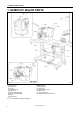
1. NAMES OF MAJOR PARTS 1. NAMES OF MAJOR PARTS 4401Q (1) Power switch (2) Control box (3) CF slot (4) Operation panel (5) Foot switch (6) Work clamp (KE-430D) (7) Button clamp (BE-438D) (8) Pulley (9) Cotton stand CF 1 TM 4400Q Safety devices (10) Finger guard (11) Eye guard (12) Thread take-up cover (13) Back cover (14) Frame side cover (15) Tension release solenoid cover is a trademark of SanDisk Corporation.
2. SPECIFICATIONS 2. SPECIFICATIONS 2-1. Machine specifications 1 2 7 F Ordinary materials Denim Knitted materials Foundation garments KE-430D Electronic direct drive lockstitch bar tacker Stitch formation Maximum sewing speed Pattern size (X x Y) BE-438D Electronic direct drive lockstitch button sewer Single needle lock stitch 3,200 rpm 2,700 rpm 40 x 30 mm max. 6.4 x 6.4 mm max.
2. SPECIFICATIONS 2-2. Program list (KE-430D) The programs shown below have been preset into the sewing machine and can be selected according to specifications. (Any program is available as long as the sewing pattern is within the work clamp and feed plate in size.) Use the work clamp and feed plate that match the respective sewing pattern selected. The sewing size is the length when the enlargement/reduction ratio is 100%. For ordinary materials (-01) No. Sewing pattern No.
2. SPECIFICATIONS For denim (-02) No. No. of stitches Sewing pattern Tacking size (mm) Length Width No. Sewing pattern No. of stitches Tacking size (mm) Length Width 80 31 16 3 83 43 24 3 81 36 16 3 84 57 24 3 82 44 16 3 85 65 24 3 For Knitted materials (-07) and foundation garments (-0F) No. No. of stitches Sewing pattern Tacking size (mm) Length Width No. Sewing pattern No.
2. SPECIFICATIONS Vertical bar tacking No. 5 Sewing pattern No. of stitches Vertical straight bar tacking Tacking size (mm) Length Width No. Sewing pattern No. of stitches Tacking size (mm) Length Width 26 28 3 10 28 19 0.3 10 27 35 3 10 29 21 0.3 10 40 32 3 16 30 28 0.3 10 41 36 3 16 46 27 0.3 20 42 44 3 20 47 44 0.
2. SPECIFICATIONS Crescent bar tacking No. No. of stitches Sewing pattern Tacking size (mm) Length Width No. Sewing pattern No. of stitches Tacking size (mm) Length Width 34 35 12 7 37 57 7 12 35 58 12 7 38 53 7 10 36 57 7 12 39 53 7 10 Crossed tacking Crossed stitching No. Sewing pattern No. of stitches Tacking size (mm) Length Width No. Sewing pattern No. of stitches Tacking size (mm) Length Width 48 70 10 10 50 84 16 16 49 93 9.6 9.
2. SPECIFICATIONS L-pattern tacking No. Sewing pattern No. of stitches Tacking size (mm) Length Width No. Sewing pattern No. of stitches Tacking size (mm) Length Width 52 60 11.3 11.2 53 60 11.3 11.2 54 78 15.3 15.2 55 78 15.3 15.2 Circular stitching No. Sewing pattern No. of stitches Tacking size (mm) Length Width No. Sewing pattern No.
2. SPECIFICATIONS 2-3. Program list (BE-438D) The programs shown below have been preset into the sewing machine. Any program is available as long as the needle drops down in the hole of the button. When sewing programs that do not have crossover stitches, the thread is trimmed after sewing of one side is completed, and then the other side is sewn. No. of threads No. of crossover stitches No.
2. SPECIFICATIONS No. of threads No. of crossover stitches No. of stitches 6-6 0 24 6-6 0 24 8-8 0 28 8-8 0 28 10-10 0 32 10-10 0 32 12-12 0 36 12-12 0 36 16 6-5 1 18 17 8-7 1 22 10-9 1 26 18 6-6 1 19 19 8-8 1 23 31 10-10 1 27 45 12-12 1 31 6-6 0 24 6-6 0 24 8-8 0 28 8-8 0 28 10-10 0 32 10-10 0 32 No. of button holes No.
2. SPECIFICATIONS No. of button holes No. Sewing pattern No. of threads No. of crossover stitches No. of stitches 6-6 1 19 10-10 1 27 6-6 0 24 *2 21 *2 34 *2 *3 22 *2 *4 6-6 0 24 10-10 0 32 10-10 0 32 46 6-6 1 19 47 8-8 1 23 43 *2 *3 35 Sewing size (mm) X Y 2.4 3.4 3.4 3.4 4 *2 *4 44 48 10-10 1 27 49 12-12 1 31 *2 Do not use the button lifter spring. *3 When sewing of one side is completed, the button clamp rises and the thread is trimmed.
3. INSTALLATION 3. INSTALLATION CAUTION Machine installation should only be carried out by a qualified technician. Contact your Brother dealer or a qualified electrician for any electrical work that may need to be done. The sewing machine head weighs approximately 56 kg. The installation should be carried out by two or more people. Do not connect the power cord until installation is complete, otherwise the machine may operate if the foot switch is depressed by mistake, which could result in injury.
3. INSTALLATION 3-2. Installing the control box Remove the eight screws (1), and then remove the control box cover (2). (3) (4) (5) (6) (7) Control box Bolts [4 pcs] Spacers [4 pcs] Plain washers [4 pcs] Nuts [8 pcs] * The recommended tightening torque for the nuts (7) is 4.0±0.1N・m. 4403Q (8) Power switch (9) Wood screws [2 pcs] (10) Staples [4 pcs] Operator 4404Q 3-3.
3. INSTALLATION 3-4. Installing the machine head (1) Pins [2 pcs] (2) Set screws [2 pcs] (3) Rubber cushion assembly [2 pcs] Place the machine head gently on top of the oil pan and the rubber cushions. Pulse motor Approx. 20mm Note: • Be careful not to clamp any cords between the machine head and the oil pan. • When holding the machine head, do not hold it by the pulse motor, otherwise it may damage the pulse motor. Approx.
3. INSTALLATION 3-5. Installing the operation panel (1) Operation panel (2) Wood screws [4 pcs] * Pass the panel cord through the hole in the table, and then insert it into the control box through the hole in the side of the control box. (3) Staples [3 pcs] 4408Q 3-6. Installing the treadle unit (1) (2) (3) (4) (5) Treadle unit Bolts [3 pcs] Plain washers [3 pcs] Spring washers [3 pcs] Nuts [3 pcs] * Use a commercially-available foot switch and connecting rod.
3. INSTALLATION 3-7. Installing the cotton stand (1) Cotton stand Note: Securely tighten the nut (4) so that the two rubber cushions (2) and the washer (3) are securely clamped and so that the cotton stand (1) does not move. 3636M 3-8. Installing the button tray (BE-438D) Install the button tray at a place convenient for operation. (1) (2) (3) (4) Button tray holder Wood screws [2 pcs] Button tray Set screw 4410Q 3-9.
3. INSTALLATION 3-10. Connecting the cords 1. Gently tilt back the machine head. 2. Pass the cord bundle through the hole in the work table. 3. Loosen the two screws (1), and then open the cord presser plate (2) in the direction of the white arrow and pass the cord bundle through the opening. 4. Securely connect the connectors as indicated in the table below. Note: • Check that the connector is facing the correct way, and then insert it firmly until it locks into place.
3. INSTALLATION < Power supply motor P. C. board > Press the tab. < PMD P. C. board > The layout for the connector may differ from that shown in the illustration depending on the version of the PMD P. C. board. Connect to connectors with the same color (e.g. black to black).
3. INSTALLATION 3-11. Connecting the ground wire CAUTION Be sure to connect the ground. If the ground connection is not secure, you run the risk of receiving a serious electric shock, and problems with correct operation may also occur. 4416Q (1) (2) (3) (4) Ground wire from upper shaft motor harness Ground wire from the machine head Ground wires from X, Y and work clamp encoder harnesses (3 wires) Ground wire from operation panel harness * The recommended tightening torque for the ground screws is 1.
3. INSTALLATION 3-12. Installing the back cover (1) Back cover (2) Screws [4 pcs] Note: Be careful not to clamp the cords when installing the back cover (1).
3. INSTALLATION 3-13. Lubrication CAUTION Do not connect the power cord until lubrication has been completed, otherwise the machine may operate if the foot switch is depressed by mistake, which could result in injury. Be sure to wear protective goggles and gloves when handling the lubricating oil and grease, so that they do not get into your eyes or onto your skin, otherwise inflammation can result.
3. INSTALLATION 3-14. Connecting the power cord Insert the power cord plug (1) into a wall outlet. 1. Attach an appropriate plug to the power cord (2). (The green and yellow wire is the ground wire.) 2. Insert the power plug into a properly-grounded AC power supply. * The inside of the control box uses single-phase power.
3. INSTALLATION 3-15. Starting up Before starting home position detection, check that the needle bar is at its highest position. Turn the machine pulley so that the index mark (1) on the pulley is inside the mark (2) on the back cover. Note: If the machine is started while the index mark (1) is not inside the mark (2), error code "E110" will be displayed. (At this time, the error will be cleared if you turn the machine pulley to set the needle to the needle up stop position.) 4420Q 1.
4. PREPARATION BEFORE SEWING 4. PREPARATION BEFORE SEWING 4-1. Installing the needle CAUTION Turn off the power switch before installing the needle, otherwise the machine may operate if the foot switch is depressed by mistake, which could result in injury. 1. Loosen the set screw (1). 2. Insert the needle (2) in a straight line as far as it will go, making sure that the long groove on the needle is at the front, and then securely tighten the screw (1). 4424Q 4-2.
4. PREPARATION BEFORE SEWING Threading mode is safe because the sewing machine will not start even when the foot switch is depressed. Turn on the power switch. 1 4421Q Press the THREAD/CLAMP key. 2 All indicators switch off • The work clamp /button clamp will lower. • The tension discs will open. THREAD/CLAMP indicator lights Menu indicators switch off 4427Q 3 Threading the thread. • When 5 minutes have passed, the buzzer will sound and the tension discs will close.
4. PREPARATION BEFORE SEWING 4-3. Winding the lower thread CAUTION Do not touch any of the moving parts or press any objects against the machine while winding the lower thread, as this may result in personal injury or damage to the machine. 4429Q 1. Place the bobbin onto the bobbin winder shaft (1). 2. Thread the thread as shown in the illustration, wind the thread around the bobbin several times, and then press the bobbin presser arm(2). 3. Turn on the power switch. 4.
4. PREPARATION BEFORE SEWING 4-4. Installing the bobbin case CAUTION Turn off the power switch before installing the bobbin case, otherwise the machine may operate if the foot switch is depressed by mistake, which could result in injury. 2534Q 30mm 2535Q 4433Q 1. 2. 3. 4. 5. 6. Pull the shuttle race cover (1) downward to open it. While holding the bobbin so that the thread winds to the right, insert the bobbin into the bobbin case.
4. PREPARATION BEFORE SEWING 4-5-2. Upper thread tension Turn the tension nut (1) (main tension) to adjust the tension as appropriate for the material being sewn. Furthermore, turn the tension nut (2) (sub-tension) to adjust the remaining length of upper thread to 35 - 40 mm, when the thread take-up lever is not used.
4. PREPARATION BEFORE SEWING 4-6. Thread nipper device This is used to stop the thread from pulling out at the sewing start, and at times when skipped stitches might easily occur. The thread nipper device operates when memory switch no. 500 is set to "ON". However, some limitations apply. Refer to "6-3. List of memory switches" for details. * The default setting for this memory switch is "OFF". [Notes on use] 1.
4. PREPARATION BEFORE SEWING 3. For sewing patterns with a short bar tack length (10 mm or less), the end of the thread that is being held by the thread nipper may poke out from the seam on the underside of the material. It is recommended that you change the thread nipper setting to "OFF" for patterns such as these. (Front) 4. If error [E690] or [E691] frequently occurs, remove the needle plate and remove any thread scraps from underneath the needle plate. (Back) Upper thread 4487Q 5.
4. PREPARATION BEFORE SEWING 4-7. Inserting the button (BE-438D) 1. Press the button clamp plate cam (1) to open the button holder (2). 2. Insert the button, making sure that the button is facing the directing shown in the illustration, then release the button clamp plate cam (1). 4115M 4-8. Adjusting the button clamp (BE-438D) 1. Insert the button in the button clamp. Confirm that the button is securely held by the clamp. 2. Loosen the shoulder screw (1), while the button is held by the clamp.
5. USING THE OPERATION PANEL (BASIC OPERATIONS) 5. USING THE OPERATION PANEL (BASIC OPERATIONS) 5-1. Name and function of each operation panel item 4435Q (1) Power indicator Illuminates when the power is turned on. (2) CAUTION indicator Illuminates when an error occurs. (3) RESET key Used to reset errors. (4) TEST key Used to start test mode. (5) TEST indicator Illuminates when the TEST key (4) has been pressed. (6) THREAD/CLAMP key Used to start threading mode or work clamp height setting mode.
5. USING THE OPERATION PANEL (BASIC OPERATIONS) (10) X-SCALE indicator Illuminates when the SELECT key (15) is pressed to shown the X-scale setting. (11) Y-SCALE indicator Illuminates when the SELECT key (15) is pressed to shown the Y-scale setting. (12) SPEED indicator Illuminates when the SELECT key (15) is pressed to shown the sewing speed setting. (13) COUNTER indicator Illuminates when the SELECT key (15) is pressed to shown the lower thread or production counter setting. (14) SPLIT No.
5. USING THE OPERATION PANEL (BASIC OPERATIONS) 5-2. Setting the program number The program number is set to 0 (feed home position check) at the time of shipment from the factory. 1. Press the or key (1) to select the program number. • The program number will flash in the PROGRAM No. display (2). 2. Depress the foot switch to the 2nd step. • The feed mechanism will move to the home position and the program number will be accepted. • The program number will stop flashing and illuminate steadily.
5. USING THE OPERATION PANEL (BASIC OPERATIONS) 5-5. Checking the sewing pattern (KE-430D) Use test feed mode to check the needle movement with only the feed mechanism operating. Check that the needle hole does not come out from the frame of the work clamp. 1 Press the TEST key. TEST indicator lights 2 Select the program number to be checked, and then set the X-scale and the Y-scale. • The program number will flash. Depress the foot switch to the 2nd step.
5. USING THE OPERATION PANEL (BASIC OPERATIONS) 5-6. Checking the sewing pattern (BE-438D) Use test feed mode to check the needle movement with only the feed mechanism operating. 1 Press the TEST key. TEST indicator lights 2 Select the program number to be checked, and then set the X-scale and the Y-scale. • The program number will flash. Depress the foot switch to the 2nd step. • The feed mechanism will move to the home position and the program number will stop flashing and illuminate steadily.
5. USING THE OPERATION PANEL (BASIC OPERATIONS) 5-7. Adjusting the work clamp / button clamp lift amount The setting for the work clamp/button clamp lift amount can be changed using the operation panel. 1 Carry out home position detection. 4441Q 2 Press the THREAD/CLAMP key. The sewing machine will switch to threading mode. • “ 1” will appear in the PROGRAM No. display, and the work clamp / button clamp will be lowered.
6. USING THE OPERATION PANEL (ADVANCED OPERATIONS) 6. USING THE OPERATION PANEL (ADVANCED OPERATIONS) 6-1. List of advanced functions While holding down the TEST key, press the corresponding combination key. 4488Q 1 Memory switch setting mode Refer to “6-2. Setting memory switches”. 2 Lower thread counter setting mode Refer to “6-4. Using the lower thread counter”. 4489Q 4490Q 3 Production counter setting mode Refer to “6-5. Using the production counter”.
6. USING THE OPERATION PANEL (ADVANCED OPERATIONS) 6-2. Setting memory switches 1 While pressing the SELECT key, turn on the power switch. * Keep pressing the SELECT key until the model name is displayed and the buzzer beeps once. All indicators switch off Or With the power turned on, press the TEST key and the TENSION/WIND key simultaneously. Menu indicators switch off TEST indicator lights 2 • The memory switch number will appear in the PROGRAM No.
6. USING THE OPERATION PANEL (ADVANCED OPERATIONS) 6-3. List of memory switches No. 001 003 100 200 300 400 401 402 500 Setting Setting items range Work clamp/button clamp lift timing when sewing is complete OFF Lifts at the final stitch position. ON Lifts after moving to the home position. 2-step work clamp OFF Disable Stops at intermediate work clamp height setting mode when foot switch is ON depressed to 1st step, and then drops fully and sewing starts when foot switch is depressed to 2nd step.
6. USING THE OPERATION PANEL (ADVANCED OPERATIONS) 6-4. Using the lower thread counter If you use the bobbin thread counter to set the number of articles which can be sewn with the amount of bobbin thread available, you can stop the bobbin thread running out in the middle of sewing a pattern. 1 While pressing the TEST key, press the key. • The initial value which was set previously will appear in the menu display.
6. USING THE OPERATION PANEL (ADVANCED OPERATIONS) 6-5. Using the production counter 1 While pressing the TEST key, press the key. • The counter value will appear in the PROGRAM No. display and the menu display as a 7-digit number. TEST indicator and SPEED indicator light COUNTER indicator flashes 2 4464Q 4465Q Press the or key to set the counter value. • The counter value can be set from [000][0000] to [999][9999].
6. USING THE OPERATION PANEL (ADVANCED OPERATIONS) 6-6. Using user programs Up to 50 different combinations of settings including program no., X-scale, Y-scale, sewing speed and work clamp height can be memorized as user programs (U1 to U50). If you are sewing certain patterns over and over again, it is useful to record the settings for these patterns into a user program. User programs are enabled when memory switch no. 400 is set to "ON".
6. USING THE OPERATION PANEL (ADVANCED OPERATIONS) 6 Next, set the work clamp height. 7 THREAD/CLAMP indicator flashes Next, set the intermediate work clamp height (only when memory switch no. 003 is "ON"). Press the SELECT key. THREAD/CLAMP indicator flashes 8 4476Q Press the or key to set the desired work clamp height. Press the SELECT key. 4477Q Press the or key to set the desired intermediate work clamp height. Press the SELECT key.
6. USING THE OPERATION PANEL (ADVANCED OPERATIONS) 1. Press the or key (1) to select the user program number that you would like to use. • If the user program number is flashing, depress the foot switch to move the feed mechanism to the home position. After this, it is not necessary to detect the home position until the next time the power is turned off and back on, even if you change the user program number.
6. USING THE OPERATION PANEL (ADVANCED OPERATIONS) 6-7. Using cycle programs Sewing patterns that have been recorded in user programs can be recorded in up to nine cycle programs (C-1 to C-9). One cycle program can contain up to a maximum of fifteen steps. When sewing the sewing patterns in numerical order, it can be useful to record them in a cycle program beforehand. Cycle programs are enabled when memory switch nos. 400 and 401 are set to "ON".
6. USING THE OPERATION PANEL (ADVANCED OPERATIONS) 5 To record another cycle program, repeat steps 2 to 4. 6 End cycle program recording mode. Press the TEST key. This completes the recording of cycle programs. • The cycle program number will flash in the PROGRAM No. display, and the sewing machine will switch to home position detection standby. TEST indicator switches off Menu indicators light 4439Q 1.
6. USING THE OPERATION PANEL (ADVANCED OPERATIONS) < Clearing a cycle program> 1 While pressing the TEST key, press the SELECT key. • Switch to user program recording mode. Check that the menu indicators are flashing. TEST indicator lights Menu indicators flash 2 4478Q Press a function key from F1 to F4. • Switch to cycle program recording mode. Press a function key from F1 to F4, or press the or key to select the cycle program number to be cleared.
6. USING THE OPERATION PANEL (ADVANCED OPERATIONS) 6-8. Direct selection You can use the function keys to directly select user program numbers and cycle program numbers. U1 to U4 and C-1 to C-4 can be selected using function keys F1 to F4. U5 to U10 and C-5 to C-9 can be selected by simultaneously pressing combinations of function keys F1 to F4 (addition). U5 / C-5 U6 / C-6 U7 / C-7 Or Or Or U8 / C-8 U9 / C-9 U10 6-9.
7. SEWING 7. SEWING CAUTION Turn off the power switch at the following times, otherwise the machine may operate if the foot switch is depressed by mistake, which could result in injury. • When threading the needle • When replacing the needle and bobbin • When not using the machine and when leaving the machine unattended Do not touch any of the moving parts or press any objects against the machine while sewing, as this may result in personal injury or damage to the machine. 4459Q 1.
8. MAINTENANCE 8. MAINTENANCE CAUTION Turn off the power switch before carrying out cleaning, otherwise the machine may operate if the foot switch is pressed by mistake, which could result in injury. Be sure to wear protective goggles and gloves when handling the lubricating oil and grease, so that they do not get into your eyes or onto your skin, otherwise inflammation can result. Furthermore, do not drink the oil or eat the grease under any circumstances, as they can cause vomiting and diarrhoea.
8. MAINTENANCE 8-2. Cleaning the control box air inlet ports Use a vacuum cleaner to clean the filter in the air inlet ports (2) of the control box (1) at least once a month. 4483Q 8-3. Draining the oil 1. Remove and empty the waste oil container (1) whenever it is full. 2. After emptying the waste oil container (1), screw it back into its original position. 2550Q 8-4. Cleaning the eye guard Wipe the eye guard clean with a soft cloth.
8. MAINTENANCE 8-7. Applying grease (Work clamp: KE-430D) Periodically apply grease to the sliding parts of the work clamp (1) and the work clamp arm (2). Note: After replacing the work clamp (1), be sure to apply grease before using it. Viewed from directly above Grease * It is recommended that you use commercially-available NIPPON OIL CORPORATION Powernoc WB 2 grease for the work clamp (1). 3922M 8-8. Applying grease (When “GREASEUP” appears) If “GrE” and “AS.UP" flash on the PROGRAM No.
8. MAINTENANCE Use Brother-specified “Grease unit (SA8837-001)”. 1. Using the tube 4087M 2. Applying grease Follow the procedure below to apply grease to the places indicated by arrows on the following page. 4502Q Grease Insert the tip of the tube (1) into the hole. While pushing the nozzle (1), squeeze the tube to apply grease to each hole. Tighten the screw (2) to push in the grease. 1. Turn off the power switch. 2. Remove the screw (2).
8. MAINTENANCE 4534Q Turn the machine pulley until the screw (1) can be seen. * Left-hand thread Be careful not to drop the screw (2) when removing it. 4535Q Once the grease has been applied, follow the procedure below to reset the cumulative number of stitches between grease applications. 1. 2. 3. 4. 5. 6. 4536Q Turn on the power switch. "GrE" and "AS.UP" will flash in the program No.
9. TABLE OF ERROR CODES 9. TABLE OF ERROR CODES DANGER Wait at least 5 minutes after turning off the power switch and disconnecting the power cord from the wall outlet before opening the face plate of the control box. Touching areas where high voltages are present can result in severe injury. If a malfunction should occur with the sewing machine, a buzzer will sound and an error code will appear in the display window. Follow the remedy procedure to eliminate the cause of the problem.
9. TABLE OF ERROR CODES Feed mechanism-related errors Code Cause and remedy X feed motor home position cannot be detected. Problem with X feed motor or poor X home position sensor connection. E200 Turn off the power, and then check that connector P10 on the PMD P.C. board and connector P2 on the main P.C. board are properly connected. X feed motor stopped abnormally. E201 Turn off the power and check that there is no problem with the X feed direction.
9. TABLE OF ERROR CODES Code E430 E440 E450 E451 E452 E474 Cause and remedy Data cannot be backed up to main P.C. board. Turn off the power, and then turn it back on again. Data memory error on main P.C. board. Turn off the power, and then turn it back on again. Model selection has not been loaded from the machine head memory. Turn off the power and check that connector P3 on the power supply motor P.C. board is properly connected. Data cannot be backed up to machine head memory.
INSTRUCTION MANUAL □ http://www.brother.com/ KE-430D, BE-438D SA3390-501 2007.12.