BE-438C INSTRUCTION MANUAL Please read this manual before using the machine. Please keep this manual within easy reach for quick reference.
Thank you very much for buying a BROTHER sewing machine. Before using your new machine, please read the safety instructions below and the explanations given in the instruction manual. With industrial sewing machines, it is normal to carry out work while positioned directly in front of moving parts such as the needle and thread take-up lever, and consequently there is always a danger of injury that can be caused by these parts.
2. Notes on safety DANGER Wait at least 5 minutes after turning off the power switch and disconnecting the power cord from the wall outlet before opening the face plate of the control box. Touching areas where high voltages are present can result in severe injury. CAUTION Environmental requirements Use the sewing machine in an area which is free from sources of strong electrical noise such as highfrequency welders. Sources of strong electrical noise may cause problems with correct operation.
CAUTION Sewing This sewing machine should only be used by operators who have received the necessary training in safe use beforehand. If using a work table which has casters, the casters should be secured in such a way so that they cannot move. The sewing machine should not be used for any applications other than sewing. Attach all safety devices before using the sewing machine. If the machine is used without these devices attached, injury may result.
3. Warning labels The following warning labels appear on the sewing machine. Please follow the instructions on the labels at all times when using the machine. If the labels have been removed or are difficult to read, please contact your nearest Brother dealer. 1 2 Safety devices Eye guard Finger guard Thread take-up cover Thread take-up solenoid cover Belt cover Frame side cover, etc. High temperature warning display 3 4 Be sure to connect the ground.
CONTENTS 1. NAME OF EACH PART .............................. 1 9. MAINTENANCE AND INSPECTION .......... 30 9-1. Checking the needle..............................................30 2. SPECIFICATIONS ...................................... 2 9-2. Cleaning the rotary hook .......................................30 2-1. Specifications......................................................... 2 9-3. Lubrication.............................................................31 2-2. Program list...................
1. NAME OF EACH PART 1.
2. SPECIFICATIONS 2. SPECIFICATIONS 2-1. Specifications Stitch formation Single needle lock stitch Maximum sewing speed Maximum pattern size 2,500rpm 0 - 6.4 × 0 - 6.4 mm TQ × 1#12 Needle Dimensions of buttons that can be sewn Outer diameter of button 8 - 30 mm (Use the optional button clamp B for diameters of 20 mm or greater.) Space between the button holes 0 - 6.4 mm Button clamp height 13 mm max.
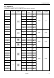
2. SPECIFICATIONS 2-2. Program list Sewing patterns are limited as shown in the table below. (Any program is available as long as the needle drops down in the hole of the button.) No. of threads No. of crossover stitches No.
2. SPECIFICATIONS No. of threads No. of crossover stitches No. of stitches 16 6-5 1 19 17 8-7 1 23 30 10-9 1 27 18 6-6 1 20 19 8-8 1 24 31 10-10 1 28 45 12-12 1 32 6-6 0 26 8-8 0 30 10-10 0 34 6-6 1 20 10-10 1 28 Program No. No. of button holes *3 20 *3 32 *3 33 *2 21 *2 34 *2*3 Sewing pattern 0 26 35 10-10 0 34 46 6-6 1 20 47 8-8 1 24 48 10-10 1 28 49 12-12 1 32 *2*3 Standard sewing width Y 3.4mm 3.4mm 2.4mm 3.4mm 3.4mm 3.
2. SPECIFICATIONS The following programs require the solenoid thread wiper (OP). No. of threads No. of crossover stitches No. of stitches 36 6-6 0 26 37 8-8 0 30 38 10-10 0 34 39 12-12 0 38 6-6 0 26 41 8-8 0 30 42 10-10 0 34 6-6 0 26 Program No. 40 No. of button holes Sewing pattern 4 * 43 * 44 10-10 0 Standard sewing length X Standard sewing width Y 3.4mm 3.4mm 2.4mm 3.4mm 34 * Do not use the button lifter spring.
3. INSTALLATION 3. INSTALLATION CAUTION Machine installation should only be carried out by a qualified technician. Contact your Brother dealer or a qualified electrician for any electrical work that may need to be done. The sewing machine head weighs more than 52 kg. The installation should be carried out by two or more people. Do not connect the power cord until installation is complete, otherwise the machine may operate if the foot switch is depressed by mistake, which could result in injury.
3. INSTALLATION 3-2. Installing the control box Check that the IM sticker is attached to the side of the control box (in the position shown in the illustration). (BE-438C machine heads can only be used with control boxes which have the IM sticker attached.) Spacers Flat washers Nuts 2454Q 1. Remove the 12 screws (1), and then open the covers (panel mounting assembly (2) and main P.C. board mounting plate (3)). Note: When opening the cover, hold it securely so that it does not fall down. 2.
3. INSTALLATION 3-3. Installing the rubber cushions Install the rubber cushions (1) with the nails (2). * Install so that the head of the nail does not protrude from the rubber surface. 2489Q 3-4. Installing the oil pan 2490Q 1. Insert the tabs of the oil pan (2) into the holes for the cushions (1), and then secure it in place with the five nails (3) so that the oil pan (2) is not at an angle. 2. While pushing the oil pan (2) down from above, screw in the oil container (4). 2491Q 3-5.
3. INSTALLATION 3-6. Installing the switching plate Install the switching plate (1) to the work table with the two wood screws (2) in the position shown in the illustration. * The switching plate and the switch bracket which is attached to the machine head prevent the sewing machine from starting when the machine head is tilted back. Therefore, this means that the sewing machine will not start if the switching plate is not installed. 2493Q 3-7. Installing the machine head 2494Q Fig. 1 2495Q 2496Q 1.
3. INSTALLATION 3-8. Installing the head rest Tap the head rest (1) into the table hole. Note: Tap the head rest securely into the table hole. 2497Q 3-9. Installing the liquid cooling tank, optional 1. Remove the rubber plug, and then push the liquid cooling tank (1). 2. Tighten it with the set screw (2).
3. INSTALLATION 3-10. Installing the operation panel The operation panel can be installed to either the top or bottom of the work table. 2500Q Top of work table Bottom of work table Table Table Rubber sheet 2 - 2.5mm 2499Q 0419Q 1. Install the rear frame (1) to the work table (top or bottom) with the four wood screws (2). * At this time, tighten the wood screws (2) until the thickness of the rubber sheet is 2 to 2.5 mm. 2. Install the front frame (3) to the rear frame (1) with the four screws (4).
3. INSTALLATION 3-12.
3. INSTALLATION 1. Gently tilt back the machine head. Note: After tilting back the machine head, do not push the face side or the pulley side from above. 2. Pass the cord bundle (1) from the machine head through the hole (2) in the work table. 3. Gently return the machine head to its original position. 4. Remove the six screws (3), and then open the control box cover (main P.C. board mounting plate (4)). Note: When opening the cover, hold it securely so that it does not fall down. 5.
3. INSTALLATION 3-13. Installing the belt cover 1. Loosen the screw (2) of the upper cover (1). 2. Insert the belt cover (3) in the direction of the arrow, and then secure it with the screw (2) and the two screws (4). Check that the cords do not get clamped by the belt cover at this time. * It is not necessary to remove the belt cover (3) when tilting back the machine head. 2456Q 3-14. Installing the foot switch 2507Q [A] [B] 2508Q 2506Q 1.
3. INSTALLATION 3-15. Installing the spool stand Assemble the spool stand (1) while referring to the spool stand instruction manual, and then install the spool stand (1) at the right side of the work table. 2509Q 3-16. Installing the button tray 1. Install the button tray holder (1) with the two flat wood screws (2) at a place convenient for operation. 2. Insert the button tray (3) into the button tray holder (1), and secure them with the screw (4).
4. LUBRICATION 4. LUBRICATION CAUTION Turn off the power switch before starting lubricating, otherwise the machine may operate if the foot switch is depressed by mistake, which could result in injury. Be sure to wear protective goggles and gloves when handling the lubricating oil and grease, so that they do not get into your eyes or onto your skin, otherwise inflammation can result. Furthermore, do not drink the oil or eat the grease under any circumstances, as they can cause vomiting and diarrhoea.
5. OPERATION 5. OPERATION 5-1. Name and function of each operation panel item 2514Q (1) POWER indicator ................. Illuminates when the power switch has been turned on. (2) RESET switch ...................... Press this switch to reset the machine when an error occurs. (3) TEST switch........................ Use this switch when you want to operate only the feed mechanism in order to check a pattern. (4) TEST indicator ..................... Illuminates when the TEST switch has been pressed.
5. OPERATION 2515Q (8) X-SCALE indicator .............. Illuminates when the SELECT switch (6) is pressed to shown the X-scale setting. (9) Y-SCALE indicator .............. Illuminates when the SELECT switch (6) is pressed to shown the Y-scale setting. (10) SPEED indicator ................. Illuminates when the SELECT switch (6) is pressed to shown the speed setting. (11) COUNTER indicator............
5. OPERATION 5-2. Operating procedure Preparation Turn on the power switch. * The POWER indicator (1) will illuminate and the program number will flash in the display window (14). Program No.
5. OPERATION 5-2-3. Setting the sewing speed 1 Press the SELECT switch (6) until the SPEED indicator illuminates. 2520Q 2 Press the DISPLAY SET switches (12) until the desired speed setting is flashing in the display window. 2603Q Note: Be sure to check the sewing pattern (refer to page 21) after setting has been completed to make sure that the needle drops down into the hole of the botton.
6. CHECKING THE SEWING PATTERN 6. CHECKING THE SEWING PATTERN When checking by operating only the feed mechanism 2. Set the X-scale and Y-scale in accordance with the hole pitch of the buttons being used. 1. Turn on the power switch. The POWER indicator will illuminate and the program number will flash in the display window. (Refer to “5-2-2. Setting the X-scale and Y-scale”.) 4. Press the TEST switch. (The TEST indicator will illuminate.) 0090Q 3. Set the button. (Refer to “7-7.
7. CORRECT USE 7. CORRECT USE 7-1. Selecting the needle and thread Needle Refer to the table at right for details on which needle and thread to select. Note: Use buttons which have a hole diameter that is greater than the value given in the table, to ensure that the needle does not touch the button. Thread TQ × 1 #11 TQ × 1 #12 TQ × 1 #14 #60 #50 Button hole diameter 1.5mm or greater 1.6mm or greater 1.7mm or greater 7-2.
7. CORRECT USE 7-4. Winding the lower thread CAUTION Do not touch any of the moving parts or press any objects against the machine while winding the lower thread, as this may result in personal injury or damage to the machine. 1. Place the bobbin all the way onto the shaft. 2. Thread the thread as shown in the illustration at right, wind the thread around the bobbin several times in the direction of the arrow, and then press the bobbin presser (1). 3. Turn on the power switch.
7. CORRECT USE 7-5. Replacing the bobbin case and threading the thread CAUTION Turn off the power switch before removing or inserting the bobbin case, otherwise the machine may operate if the foot switch is depressed by mistake, which could result in injury. 2610Q 2534Q 30mm 2535Q 1. Pull the shuttle race cover (1) toward you to open it. 2. Insert a new bobbin into the bobbin case, and then pass the thread through the slot (2) and pull it out from the thread hole (3).
7. CORRECT USE 7-6-2. Lower thread tension Adjust the thread tension to the weakest possible tension by turning the thread tension nut (1) until the bobbin case will not drop by its own weight while the thread end coming out of the bobbin case is held. Weaker Stronger 2536Q 7-6-3. Upper thread tension Turn the tension nut (1) (main tension) to adjust the tension as appropriate for the material being sewn.
7. CORRECT USE 7-6-5. Thread take-up spring tension Turn the tension stud (1) with a screwdriver. Stronger Weaker 2657Q 7-6-6. Adjusting arm thread guide R The standard position of arm thread guide R (1) is when the screw (2) is aligned with mark . To adjust the position, loosen the screw (2) and then move arm thread guide R(1). * When sewing thick material, move arm thread guide R(1) to the left. (The thread take-up amount will become greater.
7. CORRECT USE 7-7. Inserting the button 1. Press the cam plate (1) to open the button holder (2). 2. Insert the button, making sure that the button is facing the directing shown in the illustration, then release the cam plate (1). 2659Q 7-8. Adjusting the button holder 1. Insert the button in the button holder. Confirm that the button is securely held by the holder. 2. Loosen the set screw (1), while the button is held by the holder.
7. CORRECT USE 7-10. Replacing the PROM DANGER Wait at least 5 minutes after turning off the power switch and disconnecting the power cord from the wall outlet before opening the face plate of the control box. Touching areas where high voltages are present can result in severe injury. 2542Q 2461Q 2544Q 2543Q 2545Q 1. Turn off the power switch. 2. Remove the six screws (1), and then open the control box cover (main P.C. board mounting plate (2)).
8. SEWING 8. SEWING CAUTION Turn off the power switch at the following times, otherwise the machine may operate if the foot switch is depressed by mistake, which could result in injury. • When threading the needle • When replacing the needle and bobbin • When not using the machine and when leaving the machine unattended. Do not touch any of the moving parts or press any objects against the machine while sewing, as this may result in personal injury or damage to the machine. Before starting sewing ......
9. MAINTENANCE AND INSPECTION 9. MAINTENANCE AND INSPECTION CAUTION Turn off the power switch before carrying out cleaning, otherwise the machine may operate if the foot switch is pressed by mistake, which could result in injury. Be sure to wear protective goggles and gloves when handling the lubricating oil and grease, so that they do not get into your eyes or onto your skin, otherwise inflammation can result.
9. MAINTENANCE AND INSPECTION 9-3. Lubrication Note 1: Fill the machine with oil when the oil level is down to about one-third full in the oil sight glass. If oil is not added and the oil drops below this level, there is the danger that the machine may seize during operation. Note 2: Be sure to let the machine operate for a while after adding the oil. Note 3: If there is no more oil on the felt of the shuttle race base, problems with sewing may result, so add oil to the felt until it is slightly soaked.
9. MAINTENANCE AND INSPECTION 9-4. Draining the oil 1. Remove and empty the waste oil container (1) whenever it is full. 2. After emptying the waste oil container (1), screw it back into its original position. 2550Q 9-5. Cleaning the control box air inlet port Use a vacuum cleaner to clean the filter in the air inlet port (2) of the control box (1) at least once a month. * If the machine is used while the air inlet port is blocked, the inside of the control box will overheat.
10. STANDARD ADJUSTMENTS 10. STANDARD ADJUSTMENTS CAUTION Maintenance and inspection of the sewing machine should only be carried out by a qualified technician. Ask your Brother dealer or a qualified electrician to carry out any maintenance and inspection of the electrical system. Turn off the power switch and disconnect the power cord from the wall outlet at the following times, otherwise the machine may operate if the foot switch is depressed by mistake, which could result in injury.
10. STANDARD ADJUSTMENTS 10-3. Adjusting the driver needle guard Needle center line Tip 0135Q 2555Q 2556Q Turn the machine pulley to align the tip of the rotary hook with the needle center line. Then loosen the set screw (2) and turn the eccentric shaft (3) to adjust so that the driver needle guard (1) contacts the needle. If the needle contact pressure is too great, skipped stitches may occur.
10. STANDARD ADJUSTMENTS 10-6. Adjusting the thread take-up amount Thread take-up amount (stroke) Become less Become greater 2559Q 2560Q At the time of shipment from the factory, the thread take-up amount (stroke) of the thread take-up lever (1) is set to the standard setting of 5 mm. You may need to adjust this setting depending on the sewing conditions to prevent the thread from pulling out at the sewing start. [Adjustment method] Loosen the screw (2) and move the stopper (3.
10. STANDARD ADJUSTMENTS 10-7. Adjusting the movable knife Mark 2561Q 2465Q 1. Remove the top cover (1) while making this adjustment. 2. Press down on the plunger (2) of the thread trimming solenoid as shown in the illustration, and fit the roller (3) into the groove of the thread trimmer cam (4). 3. In this condition, turn the machine pulley to align the position of the roller (3) with the mark on the thread trimmer cam (4) 2563Q 2562Q 4.
10. STANDARD ADJUSTMENTS 10-7-1. Replacing the movable knife and fixed knife 2466Q 2665Q 1. Open the large shuttle hook cover, remove the screws (1) and (2), and then remove the feed plate (3). 2. Remove the two screws (4) and the two screws (5), and then remove the needle plate (6). 3. Remove the thread trimmer connecting rod (7) from the connecting rod lever pin (8). 2944Q 2945Q 4. Remove the movable knife (9) and replace it with a new one.
10. STANDARD ADJUSTMENTS 10-7-2. Adjusting the engagement of the movable knife and fixed knife 0149Q Fig. 1 Movable knife Fixed knife Cutting edge Cutting edge Cutting edge Cutting edge 2949Q 0150Q A. After the movable knife and fixed knife are properly engaged, tighten the screw as shown in Fig. 1. B. Turn the movable knife (in the direction of the arrow) while the screw is still tightened. C. Loosen the screw. D.
10. STANDARD ADJUSTMENTS 10-9. Adjusting the holding pressure Loosen the adjusting nut (1) and turn the adjusting nut (2) to the point where it is just tight enough that the material will not slip out of place when it is slightly pulled (keep pressure as slight as possible). 2667Q 10-10. Adjusting the position of the button holder 1. Loosen the two hexagonal bolts (1) and adjust the button holder body (2) by moving it. 2. Check that the needle will go through the button hole with no contact.
10. STANDARD ADJUSTMENTS 10-11. Adjusting the needle up stop position The needle up stop position is adjusted so that the index mark (2) on the machine pulley (1) is inside the mark (4) on the belt cover (3). If adjustment is necessary, loosen the screw (5) at the “U” mark of the machine pulley (1) and adjust the position of the machine pulley (1). The machine pulley (1) stops later if it is turned clockwise, and it stops earlier if it is turned counterclockwise.
10. STANDARD ADJUSTMENTS 10-13. Checking the input sensor and DIP switch input 2581Q 1. When the X-SCALE indicator (1) is illuminated and the RESET switch (3) is pressed while the TEST switch (2) is being pressed, the state of the X home position signal will appear on the display window (4). • When sensor is ON • When sensor is OFF 2.
10. STANDARD ADJUSTMENTS 10-14. Checking the input voltage 2582Q Specifications Display 200V [090 - 110] 220V [100 - 120] 230V [105 - 125] 100V 380V 400V 415V [100 - 120] Notes “100” is displayed when the input voltage is 200 V. “110” is displayed when the input voltage is 100V (for 100-V specs.), 380V (for 380-V specs.), 400V (for 400-V specs.) or 415V (for 415-V specs.). 1. 2. 3. 4. Turn on the power switch. Press the SELECT switch (1) until the Y-SCALE indicator (2) illuminates.
10. STANDARD ADJUSTMENTS 10-16. Moving stitch patterns • Programs which have already been programmed can be moved up, down and to the left and right. * Once the power switch has been turned off, the amount of movement that has been stored in memory is reset. However, if memory switch memo-28 is set to ON, you can keep the amount of movement recorded in memory. (The amount of movement is retained in memory even when the power switch is turned off.
11. USING THE COUNTERS 11. USING THE COUNTERS 11-1. Using the bobbin thread counter If you use the bobbin thread counter to set the number of articles which can be sewn with the amount of bobbin thread available, you can stop the bobbin thread running out in the middle of sewing a pattern. 1. Press the SELECT switch (1) until the COUNTER indicator (2) illuminates. 2. While pressing the TEST switch (3), press the RESET switch (4).
12. CHANGING FUNCTIONS USING THE DIP SWITCHES 12. CHANGING FUNCTIONS USING THE DIP SWITCHES 12-1. Operation panel DIP switches The functions shown in the table below can be changed by means of these DIP switches (1). * All DIP switches are set to OFF at the time of shipment. Note: Always turn off the power before setting the DIP switches. 2586Q Switch 0176Q Motion when set to ON DIPA-1 Presser does not automatically lift after sewing is completed. DIPA-2 Two-pedal mode is available.
12. CHANGING FUNCTIONS USING THE DIP SWITCHES 12-3. DIP switches inside the control box DANGER Wait at least 5 minutes after turning off the power switch and disconnecting the power cord from the wall outlet before opening the face plate of the control box. Touching areas where high voltages are present can result in severe injury. The functions can be changed as shown in the table below by changing the positions of the DIP switches (1). * All DIP switches are set to OFF at the time of shipment.
12. CHANGING FUNCTIONS USING THE DIP SWITCHES 12-4. Using user programs User program ... It can store sixteen different programs which can include details such as the program number, X scale, Y scale and sewing speed. If you are sewing certain patterns over and over again, it is useful to record the settings for these patterns into a user program. 2588Q Recording a user program 1. Turn off the power switch and then set DIP switch A-3 of the DIP switches (1) to ON. 2. Turn on the power switch.
12. CHANGING FUNCTIONS USING THE DIP SWITCHES Using a user program 1. Press the DISPLAY SET switches (10) to select the speed program number for the user program that you would like to use. * The user program except P16 can also be selected using the user program switches (11). (See below.) 2. Depress the foot switch to the second step. 3. Check the sewing pattern (see P.21), and then sew the pattern selected. * P1 to P4 can be selected using the P1 to P4 user program switches (11).
13. CHANGING SPECIAL FUNCTIONS USING THE MEMORY SWITCHES 13. CHANGING SPECIAL FUNCTIONS USING THE MEMORY SWITCHES The functions of the switches on the operation panel (1) can be changed to carry out special functions. Note: After changing the memory switch settings, press the power switch to turn the power off and then back on again. The memory switches “00 - 2F” (except “08”) are set to OFF at the time of shipment. 1. Turn on the power switch. 2. While pressing the TEST switch (2), press the BOBBIN.
13. CHANGING SPECIAL FUNCTIONS USING THE MEMORY SWITCHES Switch Motion when set to ON memo-10 The optional emergency stop switch can be used. memo-11 On when a two-stage tensioner is used. (Special order device that outputs from option output No. 1) (Normally the tension opens when output is OFF, and the tension closes when option output No. 1 is ON) memo-12 Pneumatic wiper can be used. (Special order device that outputs from option output No.
13. CHANGING SPECIAL FUNCTIONS USING THE MEMORY SWITCHES 30 to 4F are set by entering two-digit values. These values are incremented using the P2 switch, and decremented using the P4 switch. Switch Possible setting range Units Initial value Explanation Limits the maximum area in the horizontal direction (X). (Limited to 6.4 mm when settings have been initialized.) Limits the maximum area in the vertical direction (Y). (Limited to 6.4 mm when settings have been initialized.
13. CHANGING SPECIAL FUNCTIONS USING THE MEMORY SWITCHES 13-1. Using the cycle sewing function What is the cycle sewing function? The cycle sewing function lets you program up to four patterns for cycle sewing of patterns in a predeter mined order. Recording a cycle sewing program 2589Q 1. Set DIP switch (1)-3 to ON, and then record the patterns which you would like to use for cycle sewing. (Refer to “12-4. Using user programs”.
13. CHANGING SPECIAL FUNCTIONS USING THE MEMORY SWITCHES Using a cycle sewing program 1. When “c1-1” is flashing in the display window (10), press the foot switch to the second step. 2. Start sewing. 3. “c1-1”, “c1-2”, “c1-3” are sewn in order for each article, and when the last-recorded pattern has been sewn, the display returns to “c1-1". * * If you press one of the DISPLAY SET switches (11) when “c1-*” is displayed, you can return to the previous stitch pattern or skip a stitch pattern.
14. TABLE OF ERROR CODES 14. TABLE OF ERROR CODES DANGER Wait at least 5 minutes after turning off the power switch and disconnecting the power cord from the wall outlet before opening the face plate of the control box. Touching areas where high voltages are present can result in severe injury. If a malfunction should occur with the sewing machine, a buzzer will sound and an error code will appear in the display window. Follow the remedy procedure to eliminate the cause of the problem.
14. TABLE OF ERROR CODES Code E-A0 E-b0 E-d0 E-E0 Cause Home position cannot be detected (malfunction of home position sensor), or malfunction of power supply circuit board. You tried to change the program number when DIP switch A-8 was set to ON. Heat sink of control circuit board is abnormally hot. Malfunction of EEPROM (malfunction of main circuit board). E-E1 Corrupted EEPROM data, or main PROM version has been upgraded. E-E2 Corrupted EEPROM control information data.
15. GAUGE PARTS LIST 15.
16. TROUBLESHOOTING 16. TROUBLESHOOTING CAUTION Turn off the power switch and disconnect the power cord before carrying out troubleshooting, otherwise the machine will operate if the foot switch is depressed by mistake, which could result in injury. Problem Cause Check Remedy Page Button clamp does not rise. Button clamp lifter amount is too great. Distance between button clamp and top of needle plate Adjust the height of the button clamp to within 13 mm.
16. TROUBLESHOOTING Problem Cause Lower thread breaks. Skipped stitches occur. Remedy Page Lower thread tension Adjust the lower thread tension. 25 Damage File smooth or replace the affected part. Needle clearance Adjust the needle clearance. 34 Needle bar lift amount Adjust the needle bar lift amount. 33 Driver is contacting needle more than is necessary. Clearance between driver and needle Adjust the driver needle guard. 34 Needle is bent. Bent needle Replace the needle.
16. TROUBLESHOOTING Problem Thread jamming. Poor seam finish on reverse side of material. Incorrect tightness. thread Button breaks. Machine does not operate when power is turned on and foot switch is depressed. Cause Check Remedy Page Thread take-up spring tension and height are incorrect. Thread take-up spring tension and height Adjust the tension and height of the thread takeup spring. 25, 26 Incorrect needle rotary hook timing. Needle bar lift amount Adjust the needle bar lift amount.
17. OPTIONAL PARTS 17. OPTIONAL PARTS Two-pedal foot switch Two-step foot switch 0271Q The presser switch and the start switch have been separated, giving the operator more flexibility to select the best method of working. Liquid cooling tank 0272Q This is a pedal-type foot switch. Solenoid thread wiper 0273Q 0275Q This helps to prevent thread breakage caused by friction when using synthetic threads. Fill the tank with silicone oil (100mm2/s).
INSTRUCTION MANUAL 15-1, Naeshiro-cho, Mizuho-ku, Nagoya 467-8561, Japan. Phone: 81-52-824-2177 Printed in Japan 118-V38 S91V38-202 2002.10.