
Instruction manual


3. INSTALLATION
13
BE-438C
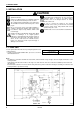
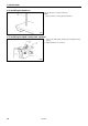
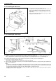
1. Gently tilt back the machine head.
Note:
After tilting back the machine head, do not push the face side or the pulley side from above.
2. Pass the cord bundle (1) from the machine head through the hole (2) in the work table.
3. Gently return the machine head to its original position.
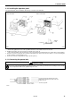
4. Remove the six screws (3), and then open the control box cover (main P.C. board mounting plate (4)).
Note:
When opening the cover, hold it securely so that it does not fall down.
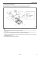
5. Loosen the two screws (5), and then open the cord presser plate (6) in the direction of the white arrow and pass the cord
bundle (1) through the opening.
6. Remove the screw (7), and then pass it through the terminal holes in the ground cord (8) from the machine head and the
ground cord (9) from the operation panel. Then re-tighten the screw (7) so that the ground cords (8) and (9) are secured
as shown in the illustration.
7. Remove the screw (10), and then pass it through the terminal hole in the ground cord (11) from the upper shaft motor.
Then re-tighten the screw (10) so that the ground cord (11) is secured as shown in the illustration.
Note:
Make sure that the ground connections are secure in order to ensure safety.
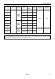
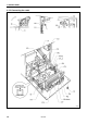
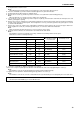
8. Securely connect connectors P1 to P8 and P11 as indicated in the table below.
Note:
Check that the connector is facing the correct way, and then insert it firmly until it locks into place.
Furthermore, lock the cord clamp at the top.
Machine head connectors
Connection location No. of pins Cord mark
Connection location
on circuit board
Cord clamps used
Head position switch 9-pin [1A] P1-A (ORG1) None
X, Y, Sewing sensor 12-pin [1] P1-B (ORG2) None
Synchronizer 5-pin [2] P2 (SYNCHRO) (G)
Machine specification
select connector
8-pin [3] P3 (SELECT) None
Thread take-up solenoid 5-pin [4] P4 (SOL2) (G)(H)
Presser solenoid
Thread trimmer solenoid
4-pin [5] P5 (SOL) (G)(H)
Pulse motor, Y 4-pin (blue) [6] P6 (YPM) (G)(H)
Pulse motor, X 4-pin [7] P7 (XPM) (G)(H)
Operation panel 26-pin None P8 (PANEL) None
Upper shaft motor 3-pin None P11 (UVW) (A)(B)(C)(D)(E)(F)
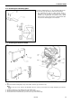
9. Secure the cord bundle (1) with the cord clamps (12) and (13).
10. Close the cord presser plate (6) in the direction of the black arrow, and secure it by tightening the screws (5).
Note:
Check that the cords do not get pulled when the machine head is tilted back gently.
11. Tighten the cover (main P.C. board mounting plate (4)) with the six screws (3).
Note:
Check that the cords do not come into contact with the fan (14) and that they are not clamped by the cover at this time.
Note:
Check that the main PROM (15) is version MN-G or later.