
Specifications


III – 5
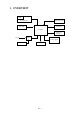
2.3 Power Transmission Mechanism
The equipment has a single drive motor whose power transmission route can be switched by
the planetary gear train and the solenoid. This switching allows the equipment to function in
four operation modes (recording, scanning, copying, and cutter driving modes).
2.3.1 Structure of the gear train
The gear train consists of two groups of gears: one group on the drive unit and the other on
the scanner frame ASSY. Mounting the drive unit onto the scanner frame ASSY makes
those two groups of gears engage with each other so that the rotation torque of the motor on
the drive unit is transmitted to the separation roller, white pressure roller, and platen.
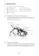
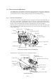
Shown below are a group of gears, the motor and solenoid on the drive unit. The cutter gear
(Q) is integrated in the cutter flange (R) whose boss is placed in the hole provided in the
cutter’s upper blade.
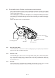
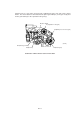
Scanner Frame ASSY
G (Gear 18L)
F (Gear 18)
E (Gear 14/20)
D (Gear 16)
H (Platen gear)
I (Reverse gear)
O (White pressure roller gear)
L (Separation roller gear)
M (Gear 23)
Scanner frame ASSY
(Front)
N (Flanged gear 23)
Clutch arm
Drive Unit (viewed from the motor mounting side)
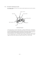
Shown below is a group of gears on the scanner frame ASSY.
Spring
A (Motor gear)
J (Gear 20)
K (Gear 16/24)
C2 (Planet gear 20A)
P (Gear 24)
Q (Cutter gear)
R (Cutter flange)
Boss of cutter flange
Drive unit
Solenoid
(Front)
C1 (Planet gear 20B)
B (Sun gear 18/82)