Please read this manual thoroughly before using the printer. Brother Laser Printer HL-1060 Series User’s Guide Keep this manual in a convenient place for quick and easy reference at all times.
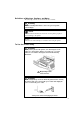
Shipment of the Printer If for any reason you must ship your printer, carefully package the printer to avoid any damage during transit. It is recommended that you save and use the original packaging. The printer should also be adequately insured with your carrier. Warning When shipping the printer, the DRUM UNIT assembly including the TONER CARTRIDGE must be removed from the printer and placed in the plastic bag.
Laser Printer HL-1060 Series User’s Guide (For USA & CANADA Only) For technical and operational assistance, please call: In USA In CANADA 1-800-276-7746 714-859-9700 Ext. 329 1-800-853-6660 514-685-6464 (outside California) (within California) (within Montreal) If you have comments or suggestions, please write us at: In USA In CANADA Printer Customer Support Brother International Corporation 15 Musick Irvine, CA 92718 Brother International Corporation (Canada), Ltd. - Marketing Dept.
USER’S GUIDE Trademarks The Brother logo is a registered trademark of Brother Industries, Ltd. Apple, the Apple Logo, AppleTalk, and Macintosh are trademarks, registered in the United States and other countries, and TrueType is a trademark of Apple Computer, Inc. Epson is a registered trademark and FX-80 and FX-850 are trademarks of Seiko Epson Corporation. Hewlett Packard is a registered trademark and HP LaserJet 5L, 5P, 4, 4L, 4P, III and IIIP are trademarks of Hewlett-Packard Company.
Definitions of Warnings, Cautions, and Notes The following conventions are used in this User’s Guide: Warning Indicates warnings that must be observed to prevent possible personal injury. Caution Indicates cautions that must be observed to use the printer properly or prevent damage to the printer. ✒ Note Indicates notes and useful tips to remember when using the printer. To Use the Printer Safely Warning After you have just used the printer, some internal parts of the printer are extremely hot.
USER’S GUIDE TABLE OF CONTENTS REGULATIONS..................................................................................................................vi CHAPTER 1 INTRODUCTION.....................................................................................1–1 ABOUT THE GUIDEBOOKS...........................................................................................1–1 Finding Out How to Use the Printer...............................................................................
TABLE OF CONTENTS CHAPTER 5 MAINTENANCE ......................................................................................5–1 REPLACING THE TONER CARTRIDGE........................................................................5–1 REPLACING THE DRUM UNIT ......................................................................................5–6 ADJUSTING THE PRINT DENSITY.............................................................................5–10 CLEANING THE PRINTER ................................
USER’S GUIDE REGULATIONS Federal Communications Commission Compliance Notice (For USA Only) This equipment has been tested and found to comply with the limits for a Class B digital device, pursuant to Part 15 of the FCC Rules. These limits are designed to provide reasonable protection against harmful interference in a residential installation.
REGULATIONS Radio Interference (220-240 V Model Only) This printer complies with EN55022(CISPR Publication 22)/Class B. Before this product is used, ensure that you use a double-shielded cable with twistedpair conductors and that it is marked “IEEE 1284 compliant”. The cable must not exceed 1.8 meters in length. Laser Safety (For 110–120 V Model Only) This printer is certified as a Class I laser product under the U.S.
USER’S GUIDE Declaration of Conformity (For Europe) We, Brother International Europe Ltd., Brother House 1 Tame Street, Guide Bridge, Audenshaw, Manchester M34 5JE, UK. declare that this product is in conformity with the following normative documents. Safety: EMC: EN 60950, EN 55022 Class B, EN 60825 EN 50082-1 following the provisions of the Low Voltage Directive 73/23/EEC and the Electromagnetic Compatibility Directive 89/336/EEC (as amended by 91/263/EEC and 92/31/EEC).
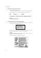
REGULATIONS For Finland and Sweden LUOKAN 1 LASERLAITE KLASS 1 LASER APPARAT Varoitus! Laitteen käyttäminen muulla kuin tässä käyttöohjeessa mainitulla tavalla saattaa altistaa käyttäjän turvallisuusluokan 1 ylittävälle näkymättömälle lasersäteilylle. Varning – Om apparaten används på annat sätt än i denna Bruksanvisning specificerats, kan användaren utsättas för osynlig laserstrålning, som överskrider gränsen för laserklass 1.
USER’S GUIDE IMPORTANT - Wiring Information (For U.K. only) If the power cord supplied with this printer is not suitable for your electrical outlet, remove the plug from the mains cord and fit an appropriate three pin plug. If the replacement plug is intended to take a fuse then fit the same fuse as the original. If a moulded plug is severed from the power cord then it should be destroyed because a plug with cut wires is dangerous if plugged into a live socket outlet.
CHAPTER 1 INTRODUCTION CHAPTER 1 INTRODUCTION ABOUT THE GUIDEBOOKS Finding Out How to Use the Printer You have two guidebooks for this printer. Read each guidebook in the following order: 1. Read the Quick Setup Guide to set up your printer and to ensure proper connection with your computer. It also contains information for installing the printer driver, fonts and Remote Printer Console Program. 2. Read the User’s Guide to get information about the following.
USER’S GUIDE ABOUT YOUR PRINTER Printer Overview Paper Support Paper Support Multi-Purpose Sheet Feeder 2 Multi-Purpose Sheet Feeder 1 Paper Stopper Paper Guide Top Cover Manual Feed Slot Extension Support Wire Control Panel Output Tray Fig. 1-1 Front View DIP switch Optional Interface Port ( Serial Interface Board RS100M) ON 12 3 4 5 6 78 slide switch Parallel Interface Port Power Switch Power Cord Fig.
CHAPTER 1 INTRODUCTION System Requirements in the Brother Printing Solution for Windows Check the following system requirements to setup and operate the printer in the Brother Printing Solution for Windows environment: • IBM PC or compatible with 80486 SX or higher microprocessor • Parallel interface (or printer port) • 4 MB or more of memory (8 MB recommended) • 10 MB of space available on your hard disk for the printer driver and all fonts • Microsoft Windows 95 or Windows 3.1/3.
USER’S GUIDE ❏ Remote Printer Console Program for DOS The utility program, Remote Printer Console (RPC), is available on a floppy disk supplied with your printer. When you operate your computer in the DOS (Disk Operating System) environment, this program allows you to easily change the default settings of the printer such as fonts, page setup, emulations and so on. This program also provides a status monitor program, which is a Terminate-and-Stay Resident (TSR) program.
CHAPTER 1 INTRODUCTION ❏ Environment-Friendly Economy Printing Mode This feature will cut your printing cost by saving toner. It is useful to obtain draft copies for proof-reading. You can select from two economy modes—25% toner saving and 50% toner saving—through the Windows printer driver supplied with your printer. Sleep Mode (Power Save Mode) When the printer is not used for a certain amount of time, sleep mode automatically reduces power consumption.
USER’S GUIDE OPERATING AND STORAGE ENVIRONMENT Please take note of the following before using the printer. Power Supply Use the printer within the specified power range. AC power: ±10% of the rated power voltage in your country Frequency: 50 Hz (220 V– 240 V) or 50/60 Hz (110–120 V) The power cord, including extensions, should not exceed 5 meters (16.5 feet). Do not share the same power circuit with other high-power appliances, particularly an air conditioner, copier, shredder and so on.
CHAPTER 1 INTRODUCTION Do not subject the printer to strong physical shocks or vibrations. Do not expose the printer to open flames or salty or corrosive gases. Do not place objects on top of the printer. Do not place the printer near an air conditioner. Keep the printer horizontal when carrying. Do not cover the slots in the top cover.
CHAPTER 2 PAPER HANDLING CHAPTER 2 PAPER HANDLING PAPER SPECIFICATIONS The multi-purpose sheet feeders can handle paper that has the following specifications. ❏ Sheet Feeder 1 (Front) / Manual slot Paper Type Cut sheet Envelopes Post Card Organizer Labels and Transparencies Paper Size A4, Letter, Legal, B5, A5, A6, Executive, Custom size (70-216 x 127-356 mm, 2.75-8.5 x 5-14 inches) DL, C5, COM-10, Monarch, 9” x 12”, C4 70-216 x 127-356 mm, 2.75-8.
USER’S GUIDE Paper Capacity in Feeder Multi-purpose Sheet Feeder: Up to 22 mm (0.87 inch) in height (up to the mark) Approx. 200 sheets of 80 g/m2 (20 lb.) or 30 sheets of 2 158 g/m (42 lb.) A4/Letter paper, or 10 envelopes Output Tray: Approx. 100 sheets of 80 g/m2 (20 lb.
CHAPTER 2 PAPER HANDLING Remarks It is recommended that you test paper, especially special sizes and types of paper, on this printer before purchasing large quantities. Avoid feeding labels with carrier sheets exposed (sheets with labels previously removed), or your printer will be damaged. Avoid using coated paper, such as vinyl coated paper. Avoid using preprinted or highly textured paper. Use a recommended type of paper, especially plain paper and transparencies, for optimum printing.
USER’S GUIDE The following types of envelopes are not recommended for use. • Damaged, curled, wrinkled, or irregularly shaped envelopes • Extremely shiny or highly textured envelopes • Envelopes with clasps • Envelopes with self-adhesive closures • Envelopes of baggy construction • Envelopes not sharply creased • Embossed envelopes • Envelopes already printed by a laser printer • Envelopes pre-printed on the inside • Envelopes that cannot be arranged uniformly when placed in a pile Fig.
CHAPTER 2 PAPER HANDLING MULTI-PURPOSE SHEET FEEDERS The printer has two multi-purpose sheet feeders that can feed plain paper, envelopes, transparencies and organizer paper. To use the multi-purpose sheet feeders, follow these steps: 1. Make sure that you have selected the proper paper source, paper size and orientation. ✒ Note • You may select the proper paper source, paper size, and orientation in your application software.
USER’S GUIDE Loading Paper into the Feeder To load paper into the feeder, follow these steps. ✒ Note This section describes loading paper into the front multi-purpose sheet feeder 1. Load paper into the rear sheet feeder 2 in the same way as described here. Remember, however, that paper sizes vary for Feeder 1 and Feeder 2. For paper sizes, see “PAPER SPECIFICATIONS” in Chapter 2. 1. Open the multi-purpose sheet feeder by gently pulling the tabs forward towards you. ( ➀ ) 2.
CHAPTER 2 PAPER HANDLING ✒ Note If you load envelopes in Feeder 1, make sure they are inserted in the direction shown on the previous page. ! Caution • If you print transparencies, load them sheet by sheet. Failure to do so may cause a double feed error. 2 • The feeder can hold up to 200 sheets of plain paper (80 g/m , 20 lb.). If you load too many sheets, paper jams could occur. • Make sure that the paper is stacked below the ▼ mark.
USER’S GUIDE ✒ Note • If the multi-purpose sheet feeder runs out of paper when you try to print, the Alarm and Paper lamps blink to alert you. You have to load paper in the feeder and push the panel switch to cancel the alarm and continue printing. If paper jams in the printer, the Alarm and Paper lamps also blink. If the error is a paper jam, clear it referring to “PAPER JAMS” in Chapter 6.
CHAPTER 2 PAPER HANDLING Two Side Printing (Manual Duplexing) The supplied printer driver for Windows 95 or Windows 3.1 allows for manual duplex printing both with Feeder 1 and Feeder 2. For more information about settings, see the help text in the printer driver. The printer prints all the even numbered pages on one side of the paper first, and then prints all the odd pages on the reverse side of the paper.
USER’S GUIDE MANUAL FEED SLOT The front multi-purpose sheet feeder 1 also has a manual feed slot. You can manually load paper sheet by sheet from this slot. You do not need to remove paper from the multi-purpose sheet feeder when using the manual feed slot. ❏ When you load one sheet of paper manually: You do not need to choose manual feed in the Setup dialog box of your printer driver.
CHAPTER 2 PAPER HANDLING ✒ Note • Insert paper firmly into the manual feed slot. • Be sure to load sheet by sheet when using the manual feed slot.
USER’S GUIDE OUTPUT TRAY AND PAPER SUPPORT WIRE The printer ejects paper with the printed surface face down into the output tray at the front of the printer. When the output tray is closed, the ejected paper comes out sheet by sheet through the slit at the front. When you open the tray, sheets can be stacked on the tray. Follow these steps to open the output tray: 1. Pull the top of the tray down ( ➀ ). 2. Extend the extension support wire ( ➁ ) and set the paper stopper ( ➂ ). Fig.
CHAPTER 3 CONTROL PANEL CHAPTER 3 CONTROL PANEL LAMPS AND SWITCH This section refers to the following lamps and switch on the printer control panel. Fee der 1 Dru 2 m Alar m R D Papeady er Tonata er Fig. 3-1 Lamps and Switch on Control Panel ✒ Note When the power switch is off or the printer is in sleep mode, all lamps including the Ready lamp are off. Ready (Paper) Lamp The Ready lamp indicates the current status of the printer.
USER’S GUIDE Data (Toner) Lamp The Data lamp indicates the current status of the print data process. Lamp Off Printer status The printer has no print data. ❍ Blinking ❍↔● On ● The printer is receiving data from the computer or the printer is processing data in memory. Print data remains in the printer memory. If the Data lamp is on for a long period of time and nothing has printed, you need to press the switch to print the remaining data. This lamp also works as the Toner lamp with the Alarm lamp.
CHAPTER 3 CONTROL PANEL Alarm Lamp The Alarm lamp blinks to indicate a printer error status such as “Cover Open” and “Memory Full.” If any other error occurs, the printer indicates the error by blinking the Alarm lamp with another lamp or by printing an error report. ✒ Note The Ready, Data and Drum lamps are used to indicate printer errors with the Alarm lamp. See “ALARM INDICATIONS AT A GLANCE” in Chapter 6 and take corrective action for the error.
USER’S GUIDE ✒ Note • When the printer goes into sleep mode, the fan will not stop until the printer engine has cooled down. • Sleep mode allows the print engine to cool, so the temperature of your room and how long the printer has been in sleep mode affects the warm-up time. This warm-up time can take up to 30 seconds. The Ready lamp blinks to indicate that the printer is warming up. • You can change the time out for the sleep mode with the supplied printer driver or Remote Printer Console program.
CHAPTER 3 CONTROL PANEL Control Features Set by the Brother Driver Page Protection If the printed images are too complex to print, the printer may print a partial image on the page. If this occurs, the printer has lost some print data and will indicate a “print overrun” error by printing an error report. The page protection feature allows the printer to create the image to be printed in memory before physically moving the paper through the printer.
USER’S GUIDE APT (Advanced Photoscale Technology) APT allows your printer to produce fine gray scales to improve the appearance of documents containing photographic images. Using this feature, the image is printed in 256 shades of gray at near photographic quality. This setting can be made by using the supplied Windows driver. Also, a demo file which can be opened within Windows Write is included on the supplied disk. Try printing it with the APT feature.
CHAPTER 4 OPTIONS CHAPTER 4 OPTIONS SERIAL INTERFACE BOARD RS100M To connect the printer to a DOS computer with a serial interface or to an Apple Macintosh computer, you need to install the optional serial interface board. When you have installed the serial interface board, you can share the printer between two computers (two IBM compatible PCs or one IBM compatible PC and one Apple Macintosh) using the parallel and serial interfaces at the same time. Automatic interface selection is a standard feature.
USER’S GUIDE If necessary, select the interface type as follows: 1. Make sure that the printer is in the off-line state. 2. Select the RS-422A(Apple) or RS-232C(IBM) interface by changing the serial interface slide switch to the right for IBM(RS-232C) or to the left side for Apple(RS-422A). Fig. 4-1 Selecting the RS-422A (Apple) or RS-232C (IBM) Serial Interface Setting the Serial Interface Parameters ✒ Note This section is only for printer models which have had the serial interface installed.
CHAPTER 4 OPTIONS If necessary, set the serial interface parameters as follows: 1. Make sure that the printer is in the off-line state. 2. Set the serial interface parameters by moving up (on) or down (off) the selectors of the dual in-line package (DIP) switch. ON 12 3 4 5 6 78 Fig.
USER’S GUIDE Table 3: Parity Settings Selector 1 On On Off Selector 2 On Off — Parity Odd Even None ✒ Note • The factory settings are indicated in bold. • If the robust Xon setting is turned on with selector 8, the printer sends Xon signals at one second intervals to the connected computer until it receives data. It is effective only if selector 7 is set to the On position for the Xon/Xoff plus DTR setting.
CHAPTER 4 OPTIONS You can connect a parallel and a serial interface cable at the same time. The auto interface selection function allows you to share the printer with two computers. To do this, connect the parallel interface cable and then connect the serial interface cable as follows: 1. Make sure that the power switch is turned off. ! Caution Be sure to turn off the power switch before connecting or disconnecting the interface cables, or the printer may be damaged. 2.
USER’S GUIDE BR-SCRIPT 2 ROM BOARD BR-3000 The BR-Script 2 ROM board provides a PostScript Level 2 language emulation. Installing this ROM board in your printer allows your printer to print PostScript data. With a BR-Script 2 ROM board installed, the automatic emulation switching function will work among HP LaserJet 5P, BR-Script 2 and EPSON FX-850 or HP LaserJet 5P, BR-Script 2 and IBM Proprinter XL.
CHAPTER 4 OPTIONS ADDITIONAL MEMORY This printer has 2.0 MByte of standard memory and has one slot for optional additional memory. The memory can be expanded up to 34 MBytes by installing a commercially available single in-line memory module (SIMM). Additional memory is useful and may be necessary if you are using the optional BR-Script 2 emulation, or the Page Protection function, full page graphics with APT or 1200 x 600 dpi resolution set to on.
USER’S GUIDE The following type of SIMMs can be installed: • 1 MByte HITACHI HB56D25632B-6A, -7A • 2 MByte HITACHI HB56D51232B-6A, -7A • 4 MByte HITACHI HB56A132BV-7A, 7AL, -7B, -7BL • 8 MByte HITACHI HB56A232BT-7A, -7AL, -7B, -7BL • 16 MByte TOSHIBA THM324000BSG-70 • 32 MByte TOSHIBA THM328020BSG-70 This printer can accept the following types of SIMMs; Speed Pin Type Height Output 60 nsec - 80 nsec 72 pin 25.4 mm (1") or less 32 bit or 36 bit ✒ Note The printer has only one slot for a SIMM upgrade.
CHAPTER 4 OPTIONS 2. Unscrew the four screws securing the rear plate of the main controller board and pull out the main controller board. Fig. 4-4 Remove the main controller board 3. Unpack the SIMM and hold it on its edge. ✒ Note Do not touch the memory chips and the surface of the main controller board. If static electricity collects, it damages the memory. 4. Install the desired size of SIMM into the slot and push gently until it clicks into place. Fig. 4-5 Install the SIMM 5.
CHAPTER 5 MAINTENANCE CHAPTER 5 MAINTENANCE REPLACING THE TONER CARTRIDGE The printer can print approximately 2,200 pages with one toner cartridge. When the toner cartridge is running low, the Alarm and Data (Toner) lamps blink once every 5 seconds to indicate toner low. ✒ Note • Actual page count will vary depending on your average document type. (i.e.: standard letter, detailed graphics, etc.
USER’S GUIDE ! Caution Keep the drum unit level after removing the toner cartridge, to avoid possible toner spill or scatter. Follow these steps to replace the toner cartridge: 1. Turn off the power switch. 2. Open the top cover. Remove the drum unit by holding each side of the drum and gently lifting the drum towards you (up and out). ✒ Note Make sure that the top cover is correctly latched open, indicated by a click Fig.
CHAPTER 5 MAINTENANCE Warning After you have just used the printer, some internal parts of the printer are extremely hot. When you open the top cover of the printer, never touch the shaded parts shown in the following illustration. High Temperature Fig. 5-3 Inside the Printer 3. Gently turn the lever on the toner cartridge forward until it stops. ✒ Note The toner cartridge cannot be removed unless the shutter is completely closed by turning the lever fully to the front. Fig.
USER’S GUIDE 4. Remove the old toner cartridge from the drum unit by pulling it out gently. Fig. 5-5 Removing the Old Toner Cartridge ! Caution Handle the toner cartridge carefully. If toner scatters on your hands or clothes, wipe or wash it off with cold water immediately. 5. Unpack the new toner cartridge, gently shake it five or six times and then remove the protective part. ! Caution • Only unpack the toner cartridge immediately before installing it into the printer.
CHAPTER 5 MAINTENANCE 6. Install the new toner cartridge into the right hand side of the drum unit. Make sure that the toner cartridge guide bar is exactly aligned with the guide slot in the drum unit to ensure that the toner cartridge and the drum unit fit together correctly. Fig. 5-7 Installing the Toner Cartridge into the Drum Unit 7. Gently turn the lever on the toner cartridge backward until it stops. Fig. 5-8 Turning the Lever to Open the Shutter 8.
USER’S GUIDE REPLACING THE DRUM UNIT The printer uses a drum unit to create the print images on paper. If the Drum lamp is on, it indicates the drum unit is nearly at the end of its life. We recommend you prepare a new drum unit to replace the current one. Even if the Drum lamp is on, you may be able to continue to print without replacing the drum unit for a while. If there is a noticeable deterioration in the output print quality even before the Drum lamp lights, then the drum unit should be replaced.
CHAPTER 5 MAINTENANCE Follow these steps to replace the drum unit: 1. Turn off the power switch. 2. Open the top cover and remove the old drum unit. Fig. 5-10 Removing the Drum Unit Warning After you have just used the printer, some internal parts of the printer are extremely hot. When you open the top cover of the printer, never touch the shaded parts shown in the following illustration. High Temperature Fig. 5-11 Inside the Printer 3.
USER’S GUIDE Fig. 5-12 Removing the Toner Cartridge 4. Unpack the drum unit and gently shake it five or six times horizontally. Fig. 5-13 Shaking the Drum Unit ! Caution • Do not remove the starter sheet. Starter Sheet Fig. 5-14 Do Not Remove the Starter Sheet • Only unpack a drum unit immediately before installing it into the printer. If an unpacked drum unit is subjected to excessive direct sunlight or room light, the unit may be damaged.
CHAPTER 5 MAINTENANCE 5. Install the toner cartridge into the new drum unit. For more information, see “REPLACING THE TONER CARTRIDGE” in this chapter. 6. Install the new drum unit into the printer. Fig. 5-15 Installing the Drum Unit 7. Close the top cover. 8. Turn on the power switch. The printer automatically ejects the starter sheet. Ejecting this sheet resets the drum life alarm. ! Caution Do not open the top cover until the printer ejects the starter sheet completely.
USER’S GUIDE ADJUSTING THE PRINT DENSITY The print density dial is located inside the printer. You can use it to adjust the amount of toner applied to the paper. When the toner cartridge and drum unit are replaced, or if the operating temperature and humidity are high or low, print conditions may change causing darker or lighter printouts. Use a screwdriver to turn the print density dial gently clockwise for darker printouts and counterclockwise for lighter printouts.
CHAPTER 5 MAINTENANCE CLEANING THE PRINTER Clean the printer exterior and interior periodically. If printed pages get stained with toner, clean the printer interior and drum unit. Cleaning the Printer Exterior Clean the printer exterior as follows: 1. Turn off the power switch and unplug the power cord. Warning There are high voltage electrodes inside the printer. Before cleaning the printer, make sure to turn off the power switch and unplug the power cord from the power outlet Fig.
USER’S GUIDE Cleaning the Printer Interior and Drum Unit Clean the printer interior and the drum unit as follows: 1. Turn off the power switch and unplug the power cord. Warning There are high voltage electrodes inside the printer. Before cleaning the printer, make sure to turn off the power switch and unplug the power cord from the outlet. Fig. 5-20 Turning off the Switch and Unplugging 2. Open the top cover of the printer. 3.
CHAPTER 5 MAINTENANCE 4. Gently wipe the scanner window with a soft dry cloth. Scanner Window Fig. 5-22 Cleaning the Scanner Window ! Caution • Do not touch the scanner window with your finger. • Do not wipe the scanner window with cleaning alcohol (isopropyl). 5. Turn the drum unit upside down carefully. ! Caution Handle the drum unit carefully as it contains toner. If toner scatters and your hands or cloths get dirty, wipe or wash it off with cold water immediately.
USER’S GUIDE 6. Clean the primary corona wire inside the drum unit by gently sliding the tab to the right and left several times. Home Position (▲) Fig. 5-23 Cleaning the Primary Corona Wire 7. Return the tab to the home position (▲ mark position) before reinstalling drum unit. ! Caution Be sure to position the tab at the home position, or printed pages may have vertical stripes. 8. Install the drum unit into the printer. See the section “REPLACING THE DRUM UNIT” in Chapter 5. 9. Close the top cover.
CHAPTER 5 MAINTENANCE Cleaning the Paper Feed Rollers Clean the paper feed rollers inside the multi-purpose sheet feeders with a clean cloth as shown below:. 1. Cleaning the Feeder 1 paper feed rollers. Fig. 5-24 Cleaning the Feeder 1 Paper Feed Rollers 2. Cleaning the Feeder 2 paper feed rollers. Fig.
USER’S GUIDE RE-PACKING THE PRINTER ! Caution Whenever you transport the printer, use the packing materials which are provided with your printer. Also, follow the steps below to re-pack the printer, or the printer may be damaged which will void the printer’s warranty. 1. Turn off the power switch and unplug the printer from the AC outlet. 2. Open the top cover. 3. Remove the drum unit assembly, referring to the previous section. ✒ Note Remove the drum unit assembly with the toner cartridge included.
CHAPTER 5 MAINTENANCE 4. Place the drum unit assembly in the plastic bag and seal the bag completely. Fig. 5-27 Placing the Drum Unit in the Plastic Bag 5. Close the top cover, the extension wire, and the output tray. 6. Wrap the printer in the plastic bag and place it in the original carton box with the original Styrofoam packing material. 7. Place any documents (manual and any documentation describing the reason for repacking printer), and drum unit assembly in the carton box as shown below. 8.
CHAPTER 6 TROUBLESHOOTING CHAPTER 6 TROUBLESHOOTING ALARM INDICATIONS AT A GLANCE Operator Calls If a recoverable error occurs, the printer indicates an ‘operator call’ by blinking the Alarm lamp and any of the following lamps. Find the error and take the proper action to correct it. The printer automatically recovers from most errors, but you may need to reset the printer with the panel switch as described below.
USER’S GUIDE For errors shown below, the printer indicates an operator call by blinking the Alarm lamp. If you use the printer with the supplied Windows driver, the status monitor will appear to indicate the error on your computer screen. The printer also prints some error messages on paper. Error Cover Open Print Overrun Action Close the top cover of the printer. • Press the panel switch to print the data remaining in the printer.
CHAPTER 6 TROUBLESHOOTING Error Serial Interface Input Buffer Overflow Action • Press the panel switch to resume printing. • Check the communication parameters such as the handshake protocols on both your computer and printer. • If the error occurs again, the interface hardware may be damaged. Consult your dealer. ✒ Note If the printer does not operate as you expect it to, it is recommended that you turn off the power switch, wait a few seconds and then turn it on again.
USER’S GUIDE Service Calls If an unrecoverable error occurs, the printer indicates the need for a service call by lighting all the lamps and then the following combination of lamps alternately: Service Call Laser BD malfunction ❍ ❍ ● ❍ ❍ Scanner malfunction ❍ ● ● ❍ ❍ ROM error Feeder Drum Alarm Ready Data Fuser malfunction ❍ ● ❍ ❍ ❍ Service Call D-RAM error Service A Service B CPU Runtime error ❍ ● ● ● ● Feeder Drum Alarm Ready Data Service Call Feeder Drum Alarm Ready Data ❍ ● ❍ ● ❍ ❍ ❍ ● ● ❍
CHAPTER 6 TROUBLESHOOTING PAPER JAMS Before you can clear a paper jam error, you need to find the location of the paper jam. Locate the position referring to the following figure. Paper Front Multi-Purpose Sheet Feeder 1 can be removed to clear paper jams Paper Top Cover Rear Multi-Purpose Sheet Feeder 2 Drum Unit Fig. 6-1 Locating Paper Jam Position After locating the position, clear the jammed paper referring to the following descriptions.
USER’S GUIDE ❏ Paper Jam in the Multi-Purpose Sheet Feeder If a paper jam has occurred inside the multi-purpose sheet feeder 1 or 2, pull the jammed paper upwards out of the feeder. Also, remove Feeder 1 and open the top cover to check that a torn piece of paper does not remain inside the printer: refer to the following sections. Feeder 1 Feeder 2 Fig. 6-3 Paper Jam in the Feeders If the paper cannot be pulled up, see the next sections “Paper Jam under Feeder 1” and “Paper Jam near the Drum Unit.
CHAPTER 6 TROUBLESHOOTING ❏ Paper Jam near the Drum Unit If a paper jam has occurred near the drum unit, open the top cover and remove the drum unit. ( ➀ ) Then, pull the jammed paper upwards slowly and out of the printer. ( ➁ ) Install the drum unit and close the top cover. Fig. 6-5 Paper Jam near the Drum Unit ❏ Paper Jam in the Fuser Unit or at the Paper Output Tray If a paper jam has occurred in the fuser unit or at the paper output tray, open the top cover and remove the drum unit.
USER’S GUIDE ! Caution Do not pull jammed paper from the output tray. Be sure to open the top cover to remove the jam, or the fuser may get dirty with toner powder and may result in toner scatter on the next printed page or pages. Fig.
CHAPTER 6 TROUBLESHOOTING Q&A This section contains questions and answers for using your printer. If you have encountered a problem, find the question relating to your problem and take the steps recommended to correct the problem. Setting Up the Printer Hardware Question The printer does not work. All lamps are off. The printer does not print. Recommendation The printer may be in sleep mode. Press the panel switch to wake up the printer.
USER’S GUIDE Setting Up the Printer for Windows Question I cannot print from my application software. Sometimes I get a Print Overrun error when printing certain documents from Windows. Sometimes I get the Memory Full message. How can I correct this? CHAPTER 6 –10 Recommendation • Make sure the supplied Windows printer driver is installed and selected with your application software.
CHAPTER 6 TROUBLESHOOTING Setting Up the Printer for DOS Question I cannot print from my application software. The printer prints, but it prints incorrect information. Sometimes it prints a couple of characters and then ejects the page, etc. The printer does not print when I press the Print Screen Key. (Data lamp On) The printer prints the first part of my document but does not print the last page.
USER’S GUIDE Setting Up the Printer for Apple Macintosh Computers When Using the Optional RS-100M Serial Interface Question I cannot print from my application software. Recommendation • Make sure that the supplied Macintosh printer driver is installed in the System Folder and it is selected with Chooser. • Check the PORT selection within the Chooser: it should match the port to which you physically attached the printer cable.
CHAPTER 6 TROUBLESHOOTING Paper Handling Question The printer does not load paper. The printer does not load paper from the manual feed slot. How can I load envelopes? What paper can I use? How can I clear paper jams? Recommendation • Check to see if the “Paper Empty” message appears on your computer screen or the Alarm and Paper lamps are blinking on the printer control panel. If so, the multi-purpose sheet feeder may be out of paper or not properly installed.
USER’S GUIDE Printing Question The printer prints unexpectedly or it prints garbage. The printer cannot print full pages of a document. An error message “Print Overrun” occurs. The printer prints the first couple of pages correctly, then some pages have text missing. The printer cannot print full pages of a document. A "Memory Full" error message occurs. My headers or footers appear when I view my document on screen but do not show up when I print them.
CHAPTER 6 TROUBLESHOOTING Print Quality ! Caution You may clear a print quality problem by replacing the drum unit with a new one if the Drum lamp is on. The drum unit is at the end of its life. Question Printouts are too dark or light. Printed pages contain white stripes. Recommendation Turn the print density dial counterclockwise for lighter images and clockwise for darker images. It has been factory set to the middle position. See “ADJUSTING THE PRINT DENSITY” in Chapter 5.
USER’S GUIDE Question Toner scatters and stains the printed page. Fig. 6-11 Scattering Toner The whole page is printed in black. Recommendation • If toner scatters over the whole printing surface, adjust the print density dial inside the printer counter clockwise. See “ADJUSTING THE PRINT DENSITY” in Chapter 5. • Clean the printer interior. See “Cleaning the Printer Interior and Drum Unit” in Chapter 5. • Make sure that you use paper that meets specifications.
CHAPTER 6 TROUBLESHOOTING Question Printed pages are blurred at the center or either edge. Here come Pat-top ,he come. One thing I can tell you is you go to be free. Come together right now, over Here come Pat-top ,he come. One thing I can tell you is you go to be free. Come together right now, over Here come Pat-top ,he come. One thing I can tell you is you go to be free. Come together right now, over me. Here come Pat-top ,he come. One thing I can tell you is you go to be free.
APPENDIX APPENDIX A PRINTER SPECIFICATIONS Printing Print Method Electrophotography by semiconductor laser beam scanning Laser Wavelength: 780 nm Output: 5 mW max Resolution 1200 (H) x 600 (V) dots/inch (for Windows DIB graphics) 600 x 600 dots/inch (for Windows and DOS) 300 x 300 dots/inch (under Apple Macintosh using the optional RS-100M) Print Quality Normal printing mode Economy printing mode (up to 25% and 50% toner saving) Print Speed Up to 10 pages/minute (when loading A4 or letter-size pap
USER’S GUIDE Drum Unit: Life Expectancy: 20,000 pages at 20 pages per job 8,000 pages at 1 page per job NOTE: There are many factors that determine the actual drum life, such as temperature, humidity, type of paper and toner that you use, the number of pages per print job, etc.. Functions Emulation Brother Printing Solution for Windows Automatic emulation selection among HP LaserJet 5P, EPSON FX-850 or IBM Proprinter XL Printer Driver Windows 3.1/3.
APPENDIX Electrical and Mechanical Power Source U.S.A. and Canada: Europe and Australia: AC 110 to 120 V, 50 / 60 Hz AC 220 to 240 V, 50 Hz Power Consumption Printing: Stand-by: Sleep: 280 W or less 60 W or less 13 W or less Noise Printing: Stand-by: 49 dB A or less 38 dB A or less Temperature Operating: Storage: 10 to 32.5°C (50 to 90.
USER’S GUIDE PARALLEL INTERFACE SPECIFICATIONS ✒ Note To ensure the highest quality performance, it is recommended that you use an IEEE 1284 compliant parallel cable between the printer and your computer. Only IEEE 1284 cables support all of the advanced printing capabilities, such as bi-directional communication. These cables will be clearly marked with “IEEE-1284”. Interface Connector Printer Side: Amphenol FCN-685J036-L/X or equivalent A shielded cable should be used. Pin Assignment Pin No.
APPENDIX ✒ Note To use bi-directional communication, an interface cable which has the pin connections above must be used. Pin 1 18 2 19 3 4 20 5 6 21 7 8 22 9 10 24 11 23 12 13 14 25 16 15 17 Shield Pin 1 19 2 20 3 21 4 22 5 23 6 24 7 25 8 26 9 27 10 28 11 29 12 17 13 15 14 30 31 33 32 34 36 35 18 16 Shield Fig.
USER’S GUIDE RESIDENT FONTS Bitmapped Fonts This printer has the following bitmapped fonts. They can be used in the HP LaserJet 5P, EPSON FX-850, and IBM Proprinter XL modes. They have the following characteristics. • • • Letter Gothic 16.66 Normal, Italic, Bold, BoldItalic (Portrait & Lanscape) OCR-A(Portrait & Lanscape) OCR-B(Portrait & Lanscape) Scalable Fonts ■ The following scalable fonts can be used in the HP LaserJet 5P, EPSON FX-850, and IBM Proprinter XL modes.
APPENDIX ■ The following scalable fonts can be used in the BR-Script mode. ( Only when you have installed the BR-Script 2 ROM board.
USER’S GUIDE SYMBOL SETS/ CHARACTER SETS OCR Symbol Sets When the OCR-A or OCR-B font is selected, the corresponding symbol set is always used. • OCR-A • OCR-B • • • • • • • • • • • • • • • Ventura US (14J) PS Math (5M) PS Text (10J) Math-8 (8M) Pi Font (15U) MS Publishing (6J) Windows 3.
INDEX INDEX A F Alarm lamp ............................... 3–3, 6–1 auto-emulation switching .................. 1–4 Factory Reset .....................................3–4 Feeder lamp .......................................3–2 B H baud rate............................................ 4–3 bitmapped font ................................. A–6 BR-Script 2 ROM board ................... 4–6 hex dump print...................................3–4 C character set......................................
USER’S GUIDE paper feed roller .............................. 5–15 paper guide........................................ 1–2 Paper lamp ................................. 3–1, 6-1 paper stopper..................................... 1–2 paper support..................................... 1–2 parallel interface pin assignment.............................. A–4 port ................................................ 1–2 parity ................................................. 4–4 post card ...........................