R Brother Laser Printer SERVICE MANUAL MODEL: HL-1030/1240/1250/1270N Read this manual thoroughly before maintenance work. Keep this manual in a convenient place for quick and easy reference at all times.
© Copyright Brother 1999 All rights reserved. No part of this publication may be reproduced in any form or by any means without permission in writing from the publisher. Specifications are subject to change without notice. Trademarks: The brother logo is a registered trademark of Brother Industries, Ltd. Apple, the Apple Logo, and Macintosh are trademarks, registered in the United States and other countries, and True Type is a trademark of Apple computer, Inc.
PREFACE PREFACE This service manual contains basic information required for after-sales service of the laser printer (hereinafter referred to as "this machine" or "the printer"). This information is vital to the service technician to maintain the high printing quality and performance of the printer. This service manual covers the HL-1030/1240/1250/1270N printers. This manual consists of the following chapters: CHAPTER 1: GENERAL Features, specifications, etc.
TABLE OF CONTENTS TABLE OF CONTENTS REGULATION ............................................................................................. vii SAFETY INFORMATION ............................................................................. ix CHAPTER 1 GENERAL...........................................................................1-1 1. FEATURES................................ ................................ ................................ ..............1-1 2. OVERVIEW ...........................
TABLE OF CONTENTS 4.2 4.3 Load Paper Manually ......................................................................................................2-10 Two Side Printing (Manual Duplexing)............................................................................2-11 4.3.1 To print on both sides of the paper from the paper cassette ............................................ 2-11 4.3.2 To print on both sides of the paper from the manual feed slot.......................................... 2-12 5.
TABLE OF CONTENTS 2.2.3 Paper eject .................................................................................................................. 3-24 2.3 Sensors .....................................................................................................................3-24 2.3.1 Cover sensors A and B ................................................................................................ 3-24 2.3.2 Toner sensor ......................................................................
TABLE OF CONTENTS CHAPTER 5 PERIODIC MAINTENANCE ...............................................5-1 1. CONSUMABLE PARTS ................................ ................................ ........................... 5-1 1.1 1.2 2. 3. PERIODICAL REPLACEMENT PARTS................................ ................................ ...5-4 PERIODICAL CLEANING ................................ ................................ ........................ 5-5 3.1 3.2 3.3 3.4 4. Drum Unit..............................
TABLE OF CONTENTS 9.5 9.6 9.7 9.8 9.9 9.10 9.11 9.12 9.13 Windows NT/LAN Server (TCP/IP) Troubleshooting ......................................................6-48 Windows 95/98 Peer to Peer Print (LPR) Troubleshooting.............................................6-48 Windows 95/98 (or later) Peer to Peer (HP JetAdmin Compatible Method) Troubleshooting ...6-49 Windows 95/98/NT 4.0 Peer to Peer Print (NetBIOS) Troubleshooting .........................6-49 Internet Print (TCP/IP) Troubleshooting.............
REGULATION REGULATION LASER SAFETY (110 - 120V MODEL ONLY) This printer is certified as a Class I laser product under the US Department of Health and Human Services (DHHS) Radiation Performance Standard according to the Radiation Control for Health and Safety Act of 1968. This means that the printer does not produce hazardous laser radiation. Since radiation emitted inside the printer is completely confined within the protective housing and external covers.
REGULATION IEC 825 (220-240V MODEL ONLY) This printer is a Class I laser product as defined in IEC 825 specifications. The label shown below is attached in countries where required. CLASS 1 LASER PRODUCT APPAREIL LASER DE CLASSE 1 LASER KLASSE 1 PRODUKT This printer has a laser diode which emits invisible laser radiation in the Laser Unit. The Laser Unit should not be opened without disconnecting the two connectors connected with the AC power supply and laser unit.
SAFETY INFORMATION SAFETY INFORMATION CAUTION FOR LASER PRODUCT (WARNHINWEIS FUR LASER DRUCKER) CAUTION: When the machine during servicing is operated with the cover open, the regulations of VBG 93 and the performance instructions for VBG 93 are valid. CAUTION: In case of any trouble with the laser unit, replace the laser unit itself. To prevent direct exposure to the laser beam, do not try to open the enclosure of the laser unit.
SAFETY INFORMATION DEFINITIONS OF WARNINGS, CAUTIONS AND NOTES The following conventions are used in this service manual: WARNING Indicates warnings that must be observed to prevent possible personal injury. ! CAUTION: Indicates cautions that must be observed to service the printer properly or prevent damage to the printer. NOTE: Indicates notes and useful tips to remember when servicing the printer. **Listed below are the various kinds of “WARNING” messages included in this manual.
CHAPTER 1 GENERAL CHAPTER1 1. GENERAL FEATURES This printer has the following features; High Resolution and Fast Print Speed True 600 x 600 dots per inch (dpi) (GDI mode) with microfine toner and up to 10 pages per minute (ppm) print speed (A4 or Letter paper). True 600 x 600 dots per inch (dpi) (GDI mode) and true 300 x 300 dots per inch (dpi) (PCL mode) with microfine toner and up to 12 pages per minute (ppm) print speed (A4 or Letter paper).
CHAPTER 1 GENERAL Enhanced Memory Management The printer provides its own data compression technology in its printer hardware and the supplied printer driver software, which can automatically compress graphic data and font data efficiently into the printer’s memory. You can avoid memory errors and print most full page 600 dpi graphic and text data, including large fonts, with the standard printer memory.
CHAPTER 1 GENERAL Bar Code Print (for HL-1250/1270N only) The printer can print the following 11 types of bar codes; • • • • Code 39 Code 128 Interleaved 2 of 5 Codabar • • • • US-PostNet ISBN UPC-A UPC-E • • • EAN-8 EAN-13 EAN-128 Network Feature (for HL-1270N only) The Brother printer has built in multi protocol network capability as standard. This allows multiple host computers to share the printer on a 10/100Mbit Ethernet network.
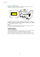
CHAPTER 1 GENERAL 2. OVERVIEW Output tray Tray extension flap Control panel Front cover Manual feed paper guides Manual feed slot Paper indicator Paper cassette Fig. 1-1 HL-1030/1240 Rear cover USB interface connector (for HL-1240 only) Parallel interface connector Power switch AC power inlet Fig.
CHAPTER 1 GENERAL 3. 3.
CHAPTER 1 GENERAL 3.
CHAPTER 1 GENERAL 3.3 Electrical and Mechanical Power source U.S.A. and Canada: Europe and Australia: AC 110 to 120V, 50 Hz/60 Hz AC 220 to 240V, 50 Hz/60 Hz Power consumption Printing (peak)*: Printing (average): Standing by: Sleep*: 940 W or less 340 W or less 80 W or less 5 W or less (HL-1030/1240) 6 W or less (HL-1250) 12W or less (HL-1270N) Noise Printing: Standing by: Temperature Operating: 10 to 32.5°C (50 to 90.
CHAPTER 1 GENERAL 3.4 Network (for HL-1270N only) Type / Speed 10/100 Base TX Ethernet Auto speed detection Protocols • TCP/IP DHCP, BOOTP, RARP, DHCP, NetBIOS over IP LPR/LPD, Port9100, Custom Port, POP3/SMTP SMB Print TELNET, SNMP, HTTP, TFTP • Novell IPX.SPX (Bindery/NDS) • AppleTalk Management • • • • • Firmware update 2MB flash ROM. Use BRAdmin32 when upgrading print server software or BOOTP, TFTP PUT/GET or IPX for Netware.
CHAPTER 1 GENERAL (2) Other paper specifications Cut sheet 2 Basis weight 64 to 105 g/m (17 to 28 lb.) Caliper 0.08 to 0.13 mm (0.003 to 0.005 in.) Moisture content 4% to 6% by weight Cut sheet 2 Envelope 2 Basis weight 64 to 158 g/m (17 to 43 lb.) 75 to 90 g/m (20 to 24 lb.) single thickness Caliper 0.08 to 0.2 mm (0.003 to 0.008 in.) 0.084 to 0.14 mm (0.003 to 0.005 in.
CHAPTER 1 GENERAL 3.5.2 Paper cassette capacity (1) Maximum load height Paper cassette: Up to 27mm (1.06 inches) in height 2 (250 sheets of 80 g/m A4/Letter paper) 10 sheets (2) Paper feed conditions Type Weight Cassette (250 sheet) 158 g/m ✕ Labels ✕ Envelopes ✕ Organizers ✕ 2 Normal paper (cut sheet) 64 to 80 g/m 2 Special paper (cut sheet) 3.5.
CHAPTER 1 GENERAL 3.6 Printing Area 3.6.1 Effective printing area The effective printing area means the area within which the printing of all the data received without any omissions can be guaranteed. (1) Supported by the engine (2) Supported by the emulation 208mm 25 4.23mm 25 2,400 (80 characters) NOTE: • The units in the above figure are dot size based on 300 dpi resolution. • 25 dots at both sides is for italic characters. 4.23mm 3.6.
CHAPTER 1 GENERAL The table below shows the print guaranteed areas for each paper size. Size A4 Letter Legal B 5 (ISO) Executive A5 A6 Organizer (J size) Organizer (K size) Organizer (L size) COM10 MONARCH C5 DL A B C D 210.0 mm 8.27” (2,480 dots) 215.9 mm 8.5” (2,550 dots) 215.9 mm 8.5” (2,550 dots) 176.0 mm 6.93” (2,078 dots) 184.15 mm 7.25” (2,175 dots) 148.5 mm 5.85” (1,754 dots) 105.0 mm 4.13” (1,240 dots) 69.85 mm 2.75” (825 dots) 95.25 mm 3.75” (1,125 dots) 139.7 mm 5.
CHAPTER 2 INSTALLATION AND BASIC OPERATION CHAPTER2 1. 1.1 INSTALLATION AND BASIC OPERATION CONDITIONS REQUIRED FOR INSTALLATION Power Supply • The source voltage must stay within ±10% of the rated voltage shown on the rating plate. • The power cord, including extensions, should not exceed 5 meters (16.5 feet). • Do no share the same power circuit with other high-power appliances, particularly an air conditioner, copier or shredder.
CHAPTER 2 INSTALLATION AND BASIC OPERATION 2. UNPACKING When unpacking the printer, check to see that all of the following components are included in the carton. Printer Paper cassette Drum unit (with Toner cartridge included) CD-ROM Documents Floppy disk Fig. 2-1 NOTE: Components may vary depending on the country.
CHAPTER 2 INSTALLATION AND BASIC OPERATION 3. INSTALL THE PRINTER You need to implement hardware setup and driver installation to use the printer. Firstly, identify the Operating System on your computer. Then, purchase the appropriate interface cable (parallel or USB) for your computer. The installation programs for the hardware setup and driver installation are contained on the supplied CD-ROM. If you do not have a CD-ROM drive, you can install the printer driver from the supplied floppy ® disk.
CHAPTER 2 INSTALLATION AND BASIC OPERATION (6) Click the Initial Setup button. Fig. 2-4 (7) You can view the Initial Setup operations in the video movie. Fig. 2-5 (8) Click the interface cable you are going to use, Parallel or USB. Fig. 2-6 (9) If you click the NOW button, you can install the printer driver immediately. (10) After the printer driver has been installed, the HL-1030, HL-1240, HL-1250 or HL1270N window will appear. Follow the onscreen messages to complete the installation. Fig.
CHAPTER 2 INSTALLATION AND BASIC OPERATION 3.2 For Windows® Users with No CD-ROM Drive If you do not have a CD-ROM drive, setup the printer following the steps below, then install the printer driver from the floppy disk. 3.2.1 Install the drum unit (1) Open the front cover. (2) Unpack the drum unit assembly and rock it from side to side 5 or 6 times to distribute the toner evenly inside the cartridge. (Fig. 2-8) Fig.
CHAPTER 2 INSTALLATION AND BASIC OPERATION (4) Extend the tray extension flap. After the printer has warmed up the Ready LED changes from blinking to lit. (Fig. 2-12) (5) Press the control panel button. The printer will print a test page. Check the test page printed correctly. Fig. 2-12 3.2.4 Connect the printer and the computer (1) Turn off the power switch. (2) Connect the parallel interface to the computer, then connect it to the printer. (Fig.
CHAPTER 2 INSTALLATION AND BASIC OPERATION 3.3 Using the USB Interface (for Windows 98 only) For the HL-1240/1250/1270N printers, the USB interface cable can be connected between the printer and PC. Prepare the printer to use the USB interface following the steps below; 3.3.1 Connect the USB interface cable (1) Check that the printer power switch is on. (2) Connect the USB interface cable to the computer, then connect it to the printer. (Fig. 2-14) USB interface cable Fig. 2-14 3.3.
CHAPTER 2 INSTALLATION AND BASIC OPERATION (3) Insert the supplied CD-ROM into the CDROM drive and select “CD-ROM drive”. Click the Next button. Fig. 2-17 (4) Click the Next button, then the USB driver will be installed. Fig. 2-18 (5) Click the Finish button. Fig. 2-19 (6) Click the Yes button, then your PC will restart. Fig.
CHAPTER 2 INSTALLATION AND BASIC OPERATION 3.3.3 Set the PC printer port Your PC printer port has to be set to “USB port”. (1) Click the Start button and select Printers in Settings. (2) Select your printer model icon in Printers so that the printer icon is highlighted. (3) Select Properties from the File menu, then click the Details tab. (4) Select BRUSB: (USB Printer Port) in the “Print to the following port” box. (Fig. 221) (5) Click the OK button to close the Properties dialog box.
CHAPTER 2 INSTALLATION AND BASIC OPERATION 4. PAPER HANDLING The printer provides two types of paper loading method; paper cassette and manual feed slot. 4.1 Load Paper into the Paper Cassette You can load normal paper and transparencies into the paper cassette. If you load paper into the paper cassette, the printer automatically feeds paper sheet by sheet and ejects the printed page into the output tray. For the details on cassette loading, refer to Subsection 3.2.
CHAPTER 2 INSTALLATION AND BASIC OPERATION The printer has a straight paper path from the manual feed slot to the rear of the printer when the rear cover is lifted up. Use this paper feed and output method when printing on thicker paper or card. (1) Select the manual feed mode in the printer driver. (2) Lift up the rear cover at the rear of the printer. (Fig. 2-25) (3) Send the print data to the printer. (4) Follow Steps (3) to (4) in the previous page to load paper.
CHAPTER 2 INSTALLATION AND BASIC OPERATION 4.3.2 To print on both sides of the paper from the manual feed slot ! CAUTION: • Before re-inserting the sheets, straighten them, or paper feed errors will occur. • The use of very thin or very thick paper is not recommended. • When the manual duplex function is used, it is possible that paper jams may occur or print quality may not be satisfactory. (1) Select the required manual duplex printing mode and manual feed mode from the driver.
CHAPTER 2 INSTALLATION AND BASIC OPERATION 5. CONTROL PANEL OPERATION There are four LEDs and a button on the control panel. The LEDs indicate the printer status, and pressing the button enables several functions in the printer. Drum LEDs Ready Paper Alarm Toner Data Control Panel Button Fig. 2-28 5.1 Ready (Paper) LED Indications The Ready LED indicates the current status of the printer. LED Printer status OFF The power switch is off, or the printer is in sleep mode.
CHAPTER 2 INSTALLATION AND BASIC OPERATION 5.2 Data (Toner) LED Indications The Data LED indicates the current status of the print data process. LED Printer status OFF The printer has no print data. Blinking The printer is receiving data from the computer or the printer is processing data in memory. ON Print data remains in the printer memory. If the Data LED is on for a long period of time and nothing has printed, you need to press the button to print the remaining data.
CHAPTER 2 INSTALLATION AND BASIC OPERATION 5.5 Control Panel Button Operations The control panel button is used for the following purposes depending on the situation. 5.6 Operation Description Cancel printing If the button is pressed during printing, the printer immediately stops printing and ejects the paper. Wake-up If the printer is in sleep mode, pressing the button wakes it up into the ready status. It will take up to 45 seconds for the printer to go into the ready status.
CHAPTER 2 INSTALLATION AND BASIC OPERATION 5.6.2 Test print mode The printer incorporates various test print modes. The printer enters into each test print mode by panel button operation. For details on test print mode, see Subsection 10.1 ‘Test Print Mode’ in CHAPTER 6.
CHAPTER 2 INSTALLATION AND BASIC OPERATION 6. NETWORK BOARD OPERATION (FOR HL-1270N ONLY) The network board installed in the back of the printer allows you to share the printer on a network. 6.1 Preparing the BR-net Board 6.1.1 Connect the Ethernet cable (1) Turn off the printer power. (2) Connect one end of the Ethernet cable to the 10/100Base TX port of the HL-1270N. Hub (3) Connect the other end of your Ethernet cable to a free port on your Ethernet hub. Fig. 2-29 (3) Turn on the printer power.
CHAPTER 2 INSTALLATION AND BASIC OPERATION 6.1.3 Print configuration page Press the Network Test button for less than 5 seconds to print a configuration page. TEST button Fig. 2-32 6.2 Functions 6.2.1 LED functions L-LED F-LED A-LED (green) (orange) (green) Fig. 2-33 L-LED (green): Link activity This LED is on if there is a valid connection to the network (either 10BaseT or 100BaseTX). It is off if no network is detected.
CHAPTER 3 THEORY OF OPERATION CHAPTER3 General Block Diagram HL-1030/1240 Fig. 3-1 shows a general block diagram of the HL-1030/1240 printer. Control system External device RAM 2MB Low-voltage power supply block 1.1 ELECTRONICS Interface block (HL-1030: Parallel) (HL1240: Parallel/USB) Video control block Engine control block High-voltage power supply block 1.
CHAPTER 3 THEORY OF OPERATION HL-1250 Optional RAM (SIMM) (max. 32Mbytes) External device Fig. 3-2 shows a general block diagram of the HL-1250 printer. Optional I/F board (Mac.
CHAPTER 3 THEORY OF OPERATION HL-1270N Fig. 3-3 shows a general block diagram of the HL-1270N printer. Optional RAM (SIMM) (max.
CHAPTER 3 THEORY OF OPERATION 1.2 Main PCB Block Diagram HL-1030/1240 Fig. 3-4 shows the block diagram of the main PCB of the HL-1030/1240 printer. A S I C CPU Core Reset Circuit Oscillator (32.7MHz) (MB86833) BUS INT Address Decoder DRAM Control Program + Font ROM 1.0 Mbytes Timer RAM (2.0 Mbytes) FIFO CDCC Parallel I/O To PC USB I/O (HL-1240 only) To PC Soft Support EEPROM (128 8 bits) EEPROM I/O Engine Control I/O To Engine PCB Fig.
CHAPTER 3 THEORY OF OPERATION HL-1250 Fig. 3-5 shows the block diagram of the main PCB of the HL-1250 printer. A S I C CPU Core Reset Circuit (MB86832) BUS Oscillator (32.7MHz) INT Address Decoder DRAM Control Program + Font ROM 4.0 Mbytes Timer RAM (4.0 Mbytes) FIFO Option RAM (SIMM) CDCC Parallel I/O (max. 32Mbytes) USB I/O Option Serial I/O (RS232C & RS422A) Soft Support EEPROM (512 x 8 bits) EEPROM I/O Engine Control I/O To Engine PCB Fig.
CHAPTER 3 THEORY OF OPERATION HL-1270N Fig. 3-6 shows the block diagram of the main PCB of the HL-1270N printer. A S I C CPU Core Reset Circuit (MB86832) BUS Oscillator (32.7MHz) INT Address Decoder DRAM Control Program + Font ROM 4.0 Mbytes Timer Flash ROM (2.0 Mbytes) FIFO RAM CDCC Parallel I/O (4.0 Mbytes) USB I/O Option RAM (SIMM) (max. 32Mbytes) Soft Support EEPROM (4096 x 8 bits) EEPROM I/O Engine Control I/O To Engine PCB To PC or Hub Network Board PCI Bus Control Fig.
CHAPTER 3 THEORY OF OPERATION 1.3 Main PCB For the entire circuit diagram of the main PCB, see Appendix 11 to 17. 1.3.1 ASIC HL-1030/1240 A Fujitsu 32bit RISC CPU, MB86833 (SPARC lite) is built in the ASIC. While the CPU is driven with a clock frequency of 33 MHz in the user logic block, it itself runs at 66 MHz, which is generated by multiplying the source clock by two.
CHAPTER 3 THEORY OF OPERATION HL-1250/1270N A Fujitsu 32bit RISC CPU, MB86832 (SPARC lite) is built in the ASIC. While the CPU is driven with a clock frequency of 33 MHz in the user logic block, it itself runs at 66 MHz, which is generated by multiplying the source clock by two. The functions of the interface block communication with external devices are described below; (1) IEEE1284 Stores the data received from the PC into DRAM as controlled by the DMA controller.
CHAPTER 3 THEORY OF OPERATION Fig.
CHAPTER 3 THEORY OF OPERATION 1.3.2 ROM HL-1030/1240 An 8 Mbits ROM (x 16 bit) is fitted. Fig. 3-9 HL-1250 Two 16 Mbits ROMs (x 16 bit) are fitted. Fig.
CHAPTER 3 THEORY OF OPERATION HL-1270N Two 32 Mbits ROMs (x 16 bit) are fitted. Fig.
CHAPTER 3 THEORY OF OPERATION 1.3.3 Flash ROM (for HL-1270N only) HL-1270N Two 8 Mbits flash ROMs (x 16 bit) are fitted. Fig. 3-12 1.3.4 DRAM HL-1030/1240 A 16M-bit DRAM (x 16 bits) is used as the RAM. Fig.
CHAPTER 3 THEORY OF OPERATION HL-1250/1270N Two 16M-bit DRAMs (x 16 bits) are used as the RAM. Fig.
CHAPTER 3 THEORY OF OPERATION 1.3.5 Optional RAM HL-1250/1270N A 32bit (72 pin) SIMM can be fitted as optional RAM. The main PCB has one slot and the capacity of SIMM can be from 1 Mbyte to 32 Mbytes. Fig.
CHAPTER 3 THEORY OF OPERATION 1.3.6 Optional serial I/O HL-1250 The interrupt of the serial I/O is input to the EXINT terminal of the ASIC, and is recognized by the CPU. A 32-byte register is provided for this I/O, which is read from and written to by the CPU. Fig. 3-16 1.3.7 PCI bus HL-1270N The interface of the PCI bus is PCI specification revision 2.2 compliant. Fig.
CHAPTER 3 THEORY OF OPERATION 1.3.8 EEPROM HL-1030/1240 The EEPROM is X24C01A type of two-wire method with a 128 x 8 bits configuration. Fig. 3-18 HL-1250 The EEPROM is X24C04 type of two-wire method with a 512 x 8 bits configuration. Fig. 3-19 HL-1270N The EEPROM is X24C32 type of two-wire method with a 4096 x 8 bits configuration. Fig. 3-20 1.3.9 Reset circuit HL-1030/1240 The reset IC is a RN5VD42A. The reset voltage is 4.2V (typ.) and the LOW period of reset is 80ms (typ.) Fig.
CHAPTER 3 THEORY OF OPERATION HL-1250/1270N The reset IC is a RN5VD42A. The reset voltage is 4.2V (typ.) and the LOW period of reset is 80ms (typ.) Fig. 3-22 1.3.10 Engine I/O HL-1030/1240 Fig. 3-22 shows the engine interface circuit. The interface with the engine PCB is by fullduplex synchronous serial method. Fig. 3-23 HL-1250/1270N Fig. 3-23 shows the engine interface circuit. The interface with the engine PCB is by fullduplex synchronous serial method. Fig.
CHAPTER 3 THEORY OF OPERATION 1.4 Engine PCB The gate array which transforms the serial signal from the main PCB into the parallel signal is mounted on the engine PCB.
CHAPTER 3 THEORY OF OPERATION 1.6 Power Supply 1.6.1 Low-voltage power supply The power supply uses a switching regulation system to generate the regulated DC power (+5V and +24V), which are converted from the AC line. The regulated output and the production code of each power supply are listed below; Regulated Output +5V / 1.6 A +24V / 2.15 A Production Code 100V: MPW1555 200V: MPW1455 For the circuit diagram of the low-voltage power supply PCB, see Appendix 20 or 21.
CHAPTER 3 THEORY OF OPERATION 1.6.2 High-voltage power supply The high-voltage power supply generates and outputs the voltages and currents for the charging, development and transfer functions. For the circuit diagram of the high-voltage power supply PCB, see Appendix 22.
CHAPTER 3 THEORY OF OPERATION 2. 2.1 MECHANICS Overview of Printing Mechanism Second eject roller Photosensitive drum Laser Unit Polygon mirror Corona wire Thermistor Cleaner Scanner motor Heat roller Development roller Rear cover Blade Agitator Toner sensor Supply roller Drum Unit First eject roller Paper feed roller Fixing Unit Paper pick-up roller Eject sensor lever Transfer roller Pressure roller Cassette pressure roller Separation pad Paper Pressure plate Paper Cassette Fig.
CHAPTER 3 THEORY OF OPERATION Laser Unit Network Board (HL-1270N) Laser Cover Sensor (B) Polygon Motor Drum Unit Main PCB Primary Charger (Corona Wire) Engine PCB HighVoltage Power Supply PCB Front Registration Sensor Rear Registration Sensor Low-Voltage Power Supply PCB Upper Paper Cassette Sensor (HL-1250/1270N) Primary Charger (Grid) Development Roller Supply Roller Transfer Roller Lower Paper Cassette Registration Sensor (HL-1250/1270N) Fixing Unit Solenoid Halogen Heater Lamp Fan Motor
CHAPTER 3 THEORY OF OPERATION 2.2 Paper Transfer 2.2.1 Paper supply The paper pick-up roller picks up one sheet of paper from the paper cassette every time it is rotated and feeds it to the paper feed roller. Pinch roller Paper feed roller Paper pick-up roller Front registration sensor lever Pinch roller Separation pad Pressure plate Fig. 3-29 The paper is gripped between the paper pick-up roller and the separation pad and separated into individual sheets.
CHAPTER 3 THEORY OF OPERATION 2.2.3 Paper eject After the printing image on the photosensitive drum is transferred onto the paper, the paper is fed to the fixing unit to fix unfixed toner onto the paper. Afterwards, the paper is ejected from the fixing unit by the first eject roller in the fixing unit. The eject sensor lever detects whether the paper is ejected correctly or not.
CHAPTER 3 THEORY OF OPERATION 2.3.2 Toner sensor Detects if there is toner in the toner cartridge. The toner sensor at the left side emits light through the window on the left side of the toner cartridge, then the toner sensor at the right side receives it when the toner is low. They also detect whether or not the drum unit is installed. (The toner cartridge is installed in the drum unit.) Toner sensor (light reception) Toner sensor (light emission) Fig. 3-33 2.4 Drum Unit 2.4.
CHAPTER 3 THEORY OF OPERATION 2.6 Print Process 2.6.1 Charging The drum is charged to approximately 870V by an ion charge which is generated by the primary charger. The charge is generated by ionization of the corona wire, which has a DC bias from the high-voltage power supply applied to it. The flow of the ion charge is controlled by the grid to ensure it is distributed evenly on the drum surface. The aluminum drum sleeve in the photosensitive drum is grounded.
CHAPTER 3 THEORY OF OPERATION The area exposed to the laser beam is the image to be printed. The surface potential of the exposed area is reduced, forming the electrostatic image to be printed. Surface Potential (V) 1 Cycle of drum 1 2 3 1 Primary charging 2 Laser beam exposure and developing (a) Unexposed area ( Non image area ) (b) Exposed area ( Image area ) 3 Transfer the image to paper (a) +870 +420 (b) +200 Drum Sleeve 0 Time Fig. 3-36 2.6.
CHAPTER 3 THEORY OF OPERATION 2.6.4 Transfer (1) Transfer process After the drum has been charged and exposed, and has received a developed image, the toner formed is transferred onto the paper by applying a negative charge to the back of the paper. The negative charge applied to the paper causes the positively charged toner to leave the drum, and adhere to the paper. As a result, the image is visible on the paper.
CHAPTER 4 DISASSEMBLY AND RE-ASSEMBLY CHAPTER4 1. DISASSEMBLY AND RE-ASSEMBLY SAFETY PRECAUTIONS To avoid creating secondary problems by mishandling, follow the warnings and precautions below during maintenance work. WARNING (1) Always turn off the power switch and unplug the power cord from the power outlet before accessing any parts inside the printer. (2) Some parts inside the printer are extremely hot immediately after the printer is used.
2.
CHAPTER 4 DISASSEMBLY AND RE-ASSEMBLY 3. 3.1 DISASSEMBLY PROCEDURE AC Cord (1) Disconnect the AC cord from the printer AC inlet. Printer AC cord Fig. 4-1 3.2 Drum Unit (1) Open the front cover and remove the drum unit from the printer. Drum unit Fig.
CHAPTER 4 DISASSEMBLY AND RE-ASSEMBLY 3.3 Paper Cassette (1) Close the front cover, pull out the paper cassette from the printer and remove the paper from the cassette. Front cover Paper cassette Fig. 4-3 (2) Remove the separation pad holder ASSY by pulling it upwards, then remove the separation pad spring from the paper cassette. Separation pad holder Separation pad spring Paper cassette Fig.
CHAPTER 4 DISASSEMBLY AND RE-ASSEMBLY NOTE: When replacing/re-assembling the separation pad holder, remove the old grease and apply a suitable amount of grease referring to the figure below; Paper pick-up roller Paper cassette Grease: Molykote PG-662 (1 rice-grain size) Fig. 4-5 (3) Turn the paper cassette upside down, then remove the cassette cover film by peeling it carefully from the underside of the cassette.
CHAPTER 4 DISASSEMBLY AND RE-ASSEMBLY (5) Keeping the paper cassette upside down, release the pressure roller holder assembly from the cassette by releasing the metal mounting plate from the plastic retaining boss. Use a flat screwdriver to press the metal plate forwards until it clears the boss and then remove the pressure roller holder assembly downwards from the cassette. (6) Remove the cassette pressure roller from the assembly, then remove the pressure roller shaft from the pressure roller.
CHAPTER 4 DISASSEMBLY AND RE-ASSEMBLY (10) Turn the cassette the correct way up and slide the two paper guides to the center of the cassette. (11) Remove the side guides Left and Right from the paper cassette. Side guide L Side guide R ➁ ➀ Paper cassette Fig. 4-9 (12) Unhook the two catches (A) of the pressure plate while pulling the plastic frame outwards, then unhook the other two catches (B) of the plate while pulling the plastic frame outwards to remove the pressure plate ASSY.
CHAPTER 4 DISASSEMBLY AND RE-ASSEMBLY NOTE: When re-assembling the pressure plate ASSY, ensure that the paper indicator arm is under the pressure plate. ! CAUTION: When unhooking the catches to remove the pressure plate, do not bend the pressure plate, gently ease the plastic cover. If the pressure plate is deformed, paper feeding problems may occur. (14) Remove the release lever extension spring. (15) Unhook the two catches and rotate the lock lever to remove it downwards from the cassette.
CHAPTER 4 DISASSEMBLY AND RE-ASSEMBLY (17) Turn the cassette upside down and remove the one M3x8 Taptite screw to remove the side guide gear. Then remove the one friction spring. (18) Remove the two side guide racks. (19) Remove the paper indicator. Taptite cup M3x8 Side guide gear Friction spring ➁ Side guide rack ➀ ➀ Side guide rack Step (19) ➀ ➁ Paper indicator Fig.
CHAPTER 4 DISASSEMBLY AND RE-ASSEMBLY 3.4 Network Board (for HL-1270N only) (1) Open the rear cover. (2) Remove the two M3x8 Taptite screws to remove the access cover. Rear cover Access cover Taptite, bind M3x8 Fig. 4-15 (3) Remove the two M3x6 Taptite screws securing the network board. (4) Disconnect the connector connected with the main PCB and remove the network board. Network board Taptite, cup M3x6 Fig.
CHAPTER 4 DISASSEMBLY AND RE-ASSEMBLY 3.5 Front Cover (1) Open the front cover. (2) Remove the four M3x8 Taptite screws from the main cover. Taptite, bind M3x8 Front cover Main cover Taptite, bind M3x8 Fig. 4-17 (3) Position the front cover at the angle of 45 degrees and release the bosses at the right and left hand sides and the link at the left hand side. (4) Remove the front cover. 45° (boss) (boss) ➀ Link Front cover ➂ Step (3) ➁ Front cover Fig.
CHAPTER 4 DISASSEMBLY AND RE-ASSEMBLY 3.6 Top Cover (1) Remove the two M3x10 Taptite screws securing the top cover. (2) Release the hooks on either side of the top cover from the bosses on the main cover by pulling the top cover forwards. Taptite, cup M3x10 Top cover Step (2) Taptite, cup M3x10 (boss) Fig. 4-19 (3) Open the rear cover, then release the hooks (A) at the right and left hand sides of the top cover while pushing them towards the side of the printer from the rear.
CHAPTER 4 DISASSEMBLY AND RE-ASSEMBLY (5) Turn the top cover upside down and remove the second eject roller ASSY by lifting the middle of the roller upwards until the roller releases from the cover. Second eject roller ASSY Top cover Fig. 4-21 3.7 Main Cover (1) Remove the two M3x8 Taptite screws from the rear of the main cover.
CHAPTER 4 DISASSEMBLY AND RE-ASSEMBLY (3) Bend the tray extension flap upwards slightly to remove the tray extension flap. Tray extension flap ➁ ➀ Main cover Fig. 4-23 (4) Release the rear cover springs Left and Right from the hooks on the main cover. (5) Remove the rear cover complete with the rear cover springs Left and Right from the main cover. (6) Remove the four pinch rollers and four pinch roller springs by moving them to the vertical and then removing them by lifting them upwards.
CHAPTER 4 DISASSEMBLY AND RE-ASSEMBLY 3.8 Laser Unit (1) Remove the three M3x16 Taptite screws. (2) Push the P harness cover to the right to release it from the hook and remove the P harness cover. (3) Disconnect the LD harness and the polygon motor connector. (4) Taking care not to touch the lens and mirror, remove the laser unit. LD harness Taptite, cup M3x16 Polygon motor harness Taptite, cup M3x16 Laser unit Taptite, cup M3x16 Polygon motor harness (hook) P harness cover Fig.
CHAPTER 4 DISASSEMBLY AND RE-ASSEMBLY 3.9 Drive Unit (1) Place the printer body carefully on its right hand side so that the drive unit is at the top. (2) Remove the five M3x6 Taptite screws securing the gear plate. (3) Disconnect the heater harness connector and release the panel PCB harness from the hooks. (4) Carefully lift the drive unit and while supporting the PCB, disconnect the main motor connector. (5) Remove the drive unit.
CHAPTER 4 DISASSEMBLY AND RE-ASSEMBLY NOTE: When replacing/re-assembling the main motor, remove the old grease and apply a suitable amount of grease referring to the figure below; Main motor ASSY Grease: Molykote PG-662 (1 rice-grain size) Fig. 4-29 (7) Remove the development joint complete with the joint spring, then remove the link. Joint spring Development joint Link Fig.
CHAPTER 4 DISASSEMBLY AND RE-ASSEMBLY 3.10 Fixing Unit (1) Place the main frame on its base so that the rear side is facing you. (2) Press the two hooks inwards to remove gear 59. (3) Disconnect the two connectors of the heater harness and release the harness from the hooks on the top of the fixing unit. (4) Remove the one M3x8 Taptite screw and two shoulder screws securing the fixing unit, taking care not to lose the contact spring fitted to the front left hand.
CHAPTER 4 DISASSEMBLY AND RE-ASSEMBLY NOTE: When re-assembling the fixing unit, align the fixing unit frame at the drive unit side into the concave part of the main frame. Fixing unit Main frame Main frame (concavity) Fixing unit Fig. 4-33 (7) Remove the M3x10 screw to remove the star wheel holder ASSY from the fixing unit by lifting the left hand end of the assembly slightly and then moving the assembly to the right to release the right hand end from the fixing unit frame.
CHAPTER 4 DISASSEMBLY AND RE-ASSEMBLY (8) Remove the two M3x20 Taptite screws from the top of the fixing unit frame. (9) Release the thermistor harness from the hooks. (10) Release the two hooks at the right and left sides securing the fixing unit cover to the fixing unit frame. (hook) (hook) Thermistor harness Fixing unit frame Taptite, cup M3x20 Thermistor harness Taptite, cup M3x20 (hook) Fixing unit frame (hook) Fig. 4-35 (11) Remove the fixing unit cover from the fixing unit frame.
CHAPTER 4 DISASSEMBLY AND RE-ASSEMBLY (12) Remove the one M3x10 Taptite screw securing the halogen lamp connector plate at the drive unit side of the fixing unit frame and then loosen the M3x6 screw at the other side. (13) Lift the right hand end of the heat roller and remove the halogen heater lamp from the heat roller. Halogen heater lamp Screw, cup M3x6 Heat roller Colored side 115V: Yellow 230V: Purple Taptite, pan M3x10 Halogen lamp connector plate Heat roller Halogen heater lamp Fig.
CHAPTER 4 DISASSEMBLY AND RE-ASSEMBLY (14) Lift and remove the heat roller. The heat roller gear will also come off. (15) Remove the heat roller bearing from the left hand end of the heat roller. To remove the bearing at the gear side, first remove the two washers, then remove the bearing. Heat roller bearing Heat roller Heat roller bearing Washer Heat roller gear Washer Fig. 4-39 ! CAUTION: Never touch the surface of the heat roller.
CHAPTER 4 DISASSEMBLY AND RE-ASSEMBLY • When re-assembling the heat roller bearing which is assembled at the heat roller gear side, fix the bearing onto the heat roller so that the embossment whose thickness is 0.5mm is at the top. Heat roller gear Heat roller bearing Heat roller (embossment) Fig. 4-41 • When re-assembling the heat roller to the fixing unit frame, ensure you do not damage the heat roller with the four hooks on the fixing unit frame.
CHAPTER 4 DISASSEMBLY AND RE-ASSEMBLY (16) Remove the heat roller cleaner complete with the cleaner spring from the fixing unit frame by lifting it upwards until the spring releases from the frame. (17) Remove the cleaner spring from the heat roller cleaner. Heat roller cleaner Cleaner spring Fixing unit frame Cleaner spring Heat roller cleaner Fig.
CHAPTER 4 DISASSEMBLY AND RE-ASSEMBLY NOTE: • When re-assembling the pressure roller cleaner complete with the cleaner spring onto the fixing unit cover, ensure the direction of the roller is correct referring to the figure above. • Ensure also that the spring is seated correctly in the locating channel and does not protrude from either end. (21) Release the thermistor harness from the hooks on the fixing unit frame and then remove the one M3x12 Taptite screw and remove the thermistor.
CHAPTER 4 DISASSEMBLY AND RE-ASSEMBLY (22) Press the two catches holding the idle gear 13 to the frame and then remove the idle gear 13. Slide the first eject roller to the left until the slot in the roller shaft aligns with the slot in the frame and then remove the roller by pulling it forwards. Fixing unit frame First eject roller Idle gear 13 Fig. 4-47 (23) Remove the eight eject pinch rollers and pinch springs by lifting them upwards until the springs release from the frame.
CHAPTER 4 DISASSEMBLY AND RE-ASSEMBLY PR2000057 (24) Turn the frame up-side down. Remove the black films (4 pcs.) and then remove the pick off fingers (4 pcs.) using a piece of tweezers. Pick off finger Film Tweezers Pick off finger Fig. 4-48a (25) Release the paper eject actuator from the hook on the fixing unit cover, and then slide the paper eject actuator to the right direction to remove the paper eject actuator and the eject paper spring from the fixing unit cover.
CHAPTER 4 PR2000057 DISASSEMBLY AND RE-ASSEMBLY NOTE: When re-assembling the paper eject actuator and the eject paper spring to the fixing unit cover, ensure the paper eject actuator is seated correctly in the locating channel referring to the figure below; Paper eject actuator Fixing unit cover Eject actuator spring Fig.
CHAPTER 4 DISASSEMBLY AND RE-ASSEMBLY 3.11 Base Plate (1) Turn the main frame upside down. (2) Remove the five M4x10 Taptite screws and 16 (sixteen) M3x8 Taptite screws from the base plate. (3) Slide the base plate to the rear of the printer to remove it. ! CAUTION: Do not remove the ground wire connected to the base plate if it is not necessary to remove the low-voltage power supply unit. Unnecessary disconnection of the ground wire may cause increased printer noise.
CHAPTER 4 DISASSEMBLY AND RE-ASSEMBLY ! CAUTION: • When re-assembling the base plate, be sure that the ground wire connected to the paper feed roller ASSY is fixed into the slit on the plastic chute referring to the figure below; Ground wire Plastic chute (slit) Main frame Fig.
CHAPTER 4 DISASSEMBLY AND RE-ASSEMBLY 3.12 Main PCB ASSY NOTE: For HL-1250/1270N only Ensure that any installed SIMM memory is removed BEFORE removing the main PCB. (1) Remove the two M3x8 screws from the I/F plate to release the main PCB. (2) Lift the insulation sheet and remove the main PCB ASSY. (3) Disconnect the three connectors for the low-voltage power supply, engine PCB and LD.
CHAPTER 4 DISASSEMBLY AND RE-ASSEMBLY 3.14 Low-Voltage Power Supply PCB ASSY (1) Remove the M3x8 Taptite screw to remove the insulation sheet. (2) Slightly lift up the low-voltage power supply PCB ASSY from the frame and disconnect the engine PCB connector. Then lift the power supply PCB ASSY further and disconnect the halogen heater lamp connector. (3) Remove the M3.5x6 screw to disconnect the ground wire from the base plate.
CHAPTER 4 DISASSEMBLY AND RE-ASSEMBLY PR99188 ! CAUTION: Be sure to attach the film to the AC inlet ASSY in the following cases referring to the figure below; • If the film is not attached to the AC inlet on the printer you are servicing. • If the film is damaged, or the adhesive is weak. AC inlet ASSY Film Fig.
CHAPTER 4 DISASSEMBLY AND RE-ASSEMBLY 3.15 Engine PCB ASSY / High-Voltage Power Supply PCB ASSY (1) Remove the M4x12 Taptite screw to remove the insulation sheet. (2) Remove the three M4x12 Taptite screws securing the engine PCB and the high-voltage power supply PCB. (3) Lift the engine PCB and high-voltage power supply PCB together and disconnect the connector which connects two PCBs together to remove the high-voltage power supply PCB ASSY.
CHAPTER 4 DISASSEMBLY AND RE-ASSEMBLY (5) Disconnect the 11 (eleven) connectors for HL-1030/1240 or 12 (twelve) connectors for HL1250/1270N from the engine PCB to remove the engine PCB ASSY.
CHAPTER 4 DISASSEMBLY AND RE-ASSEMBLY 3.16 Panel PCB ASSY NOTE: Be sure to remove the drive unit and disconnect the panel PCB connector on the engine PCB before removing the panel PCB ASSY. (1) Remove the M3x6 Taptite screw, then remove the panel PCB ASSY. Panel PCB Taptite, cup M3x6 Fig. 4-57 3.17 Solenoid ASSY NOTE: Be sure to remove the drive unit and disconnect the solenoid connector on the engine PCB before removing the solenoid ASSY.
CHAPTER 4 DISASSEMBLY AND RE-ASSEMBLY (4) Release the catch and remove the clutch levers for the feed roller and pick-up roller. Clutch lever spring Clutch lever (for paper feed roller) Clutch lever (for paper feed roller) Rod Clutch lever (for paper pick-up roller) Clutch lever (for paper pick-up roller) Solenoid Main frame Fig. 4-59 ! CAUTION: • When removing the clutch levers, the clutch lever spring may come off. Be sure not to lose it.
CHAPTER 4 DISASSEMBLY AND RE-ASSEMBLY (6) Turn the main frame upside down. (7) Remove the two M3x6 Taptite screws and release the solenoid harness from the hook and remove the cassette guide L/F. Step (7) Cassette guide L/F Taptite, cup M3x6 Fig. 4-61 (8) Remove the M3x4 screw and the tape on the solenoid harness and remove the solenoid ASSY. Tape Main frame Spring Rod Solenoid ASSY Screw, bind M3x4 Fig. 4-62 ! CAUTION: When removing the solenoid, the solenoid rod and spring may come off.
CHAPTER 4 DISASSEMBLY AND RE-ASSEMBLY 3.18 Fan Motor ASSY NOTE: Be sure to remove the fixing unit and disconnect the fan motor connector on the engine PCB before removing the fan motor ASSY. (1) Place the main frame so that the fan motor ASSY is at the top. (2) Remove the two M3x6 Taptite screws securing the fan cover. (3) Remove the fan motor ASSY with the fan cover and remove the fan motor ASSY from the cover.
CHAPTER 4 DISASSEMBLY AND RE-ASSEMBLY 3.19 Toner Sensor PCB ASSY (Light Emission) NOTE: Be sure to disconnect the toner sensor (light emission) connector on the engine PCB before removing the toner sensor PCB ASSY (light emission). (1) Release the hooks of the toner sensor PCB ASSY (light emission) and remove it. Toner sensor PCB ASSY (light emission) (hooks) (hook) Fig. 4-65 3.
CHAPTER 4 DISASSEMBLY AND RE-ASSEMBLY 3.21 Paper Pick-up Roller ASSY NOTE: Be sure to remove all the covers and the base plate before removing the paper pick-up roller ASSY. (1) Place the main frame upside down. (2) Unhook the hook to remove the inner gear 54, gear 45 and gear 20 from the main frame. (3) Remove the bearing from the paper pick-up roller shaft. (4) Release the hook on the bearing at the other side of the shaft and remove the paper pickup roller ASSY and the shaft from the main frame.
CHAPTER 4 DISASSEMBLY AND RE-ASSEMBLY 3.22 Paper Feed Roller ASSY NOTE: Be sure to remove all the covers and the PCBs before removing the paper feed roller ASSY. (1) Unhook the black plastic hook on the shaft to remove gear 21. Gear 21 (hook) Fig. 4-69 ! CAUTION: The plastic hook holding gear 21 will break easily if it is not fully released before the gear is pulled to remove it. Ensure that the hook is fully released BEFORE attempting to remove gear 21. (2) Turn the main frame the right way up.
CHAPTER 4 DISASSEMBLY AND RE-ASSEMBLY PR2000051 3.23 Outer Chute 1 (1) Remove two M3x6 Taptite screws and two M3x8 Taptite screws to remove the outer chute 2 ASSY. (2) Unhook two hooks using a slotted screwdriver and then remove the outer chute 1. Outer chute 1 Outer chute 2 ASSY Fig.
CHAPTER 4 DISASSEMBLY AND RE-ASSEMBLY 4. PACKING Insertion sheet Accessory bag Accessory carton AC Cord Pad Drum Unit (with Toner Cartridge included) Pad Printer Carton Fig.
CHAPTER 5 PERIODIC MAINTENANCE CHAPTER5 PERIODIC MAINTENANCE To avoid creating secondary problems by mishandling, follow the warnings below during maintenance work. WARNING (1) Always turn off the power switch and unplug the power cord from the power outlet before accessing any parts inside the printer. (2) Some parts inside the printer are extremely hot immediately after the printer is used.
CHAPTER 5 PERIODIC MAINTENANCE (4) Install the toner cartridge into the new drum unit until it locks into place, indicated by a click. When the toner cartridge is installed correctly, the lock lever is lifted automatically. (Fig. 5-2) (5) Install the new drum unit into the printer. Check that the printer is turned on, the front cover is open and the Drum and Alarm LEDs illuminate. Fig. 5-2 (6) Press the control panel button until all the LEDs are on. (The LED turns on in sequence from top to bottom.
CHAPTER 5 PERIODIC MAINTENANCE (4) Remove the protective cover. (Fig. 5-4) (5) Install the new toner cartridge into the drum unit until it locks into place, indicated by a click. When the toner cartridge is installed correctly, the lock lever is lifted automatically. Fig. 5-4 (6) Clean the primary corona wire inside the drum unit by gently sliding the wire cleaner (blue tab) to the right end and left end several times. (Fig.
CHAPTER 5 PERIODIC MAINTENANCE 2. PERIODICAL REPLACEMENT PARTS Periodical replacement parts are the parts to be replaced periodically to maintain product quality. These parts would affect the product quality greatly if they lost their function even if they do not appear to be damaged or there is no change in their appearance.) The periodical replacement parts listed below should be replaced at the service center referring to the service life.
CHAPTER 5 PERIODIC MAINTENANCE 3. PERIODICAL CLEANING Clean the following parts periodically to avoid any printer problems or print image defects. ! CAUTION: While drum unit and scanner window cleaning basically can be implemented by the end user, the electrical terminals inside the printer and on the drum unit should be cleaned by a service technician. Instruct the users not to touch those terminals. 3.1 Cleaning the Printer Exterior Clean the printer exterior to keep the printer clean.
CHAPTER 5 PERIODIC MAINTENANCE 3.3 Cleaning the Scanner Window When replacing the drum unit or toner cartridge with a new one, be sure to clean the scanner window. 1) Turn off the power switch and unplug the power cord. 2) Remove the drum unit from the printer. 3) Gently wipe the scanner window (colored magenta in the figures below) with a soft dry cloth. Fig. 5-8 ! CAUTION: • Do not touch the scanner window with your fingers. • Do not wipe the scanner window with cleaning alcohol (isopropyl).
CHAPTER 5 PERIODIC MAINTENANCE 4.
CHAPTER 5 PERIODIC MAINTENANCE 5-8
CHAPTER 6 TROUBLESHOOTING CHAPTER6 1. 1.1 TROUBLESHOOTING INTRODUCTION Initial Check (1) Operating environment Check if : • The source voltage stays within ±10% from the rated voltage shown on the rating plate. • The printer is installed on a solid, level surface. • The room temperature is maintained between 10°C and 32.5°C. The relative humidity is maintained between 20% and 80%. • The printer is not located in a dusty place. • The printer is not exposed to ammonia fumes or other harmful gases.
CHAPTER 6 TROUBLESHOOTING • Condensation on the corona unit may cause corona charge leakage. • Condensation on the hopper plate and separation pad may cause paper feed troubles. If condensation has occurred, print several pages or leave the printer for 2 hours to allow it to reach room temperature. If the drum unit is unpacked soon after it is moved from a cold room to a warm room, condensation may occur inside the unit, which may cause incorrect images.
CHAPTER 6 TROUBLESHOOTING 1.3 Identify the Problem If you encounter any printer error or problem, first identify it referring to the chart below, then see the appropriate section. NOTE: The following troubleshooting sections contain both the actions which users should take or check and the ones which service technicians should perform. The printer does not print. Printed page has a problem. LED is blinking. Printed image has a problem. 2.1 'Operator Calls' 2.
CHAPTER 6 TROUBLESHOOTING 2. 2.1 OPERATOR CALLS & SERVICE CALLS Operator Calls An ‘operator call’ which the printer indicates on the LEDs is user recoverable. Identify the error from the table below and take the corrective action described for each indication to correct it. The printer automatically recovers from most errors, but it may also be necessary to reset the printer with the control panel button. LED Indication Alarm LED is blinking. Error Cover open Ready & Alarm LEDs are blinking.
CHAPTER 6 TROUBLESHOOTING PR99180 Type of error Fuser Malfunction Laser BD Malfunction Scanner Malfunction ROM Error Drum Ready D-RAM Error Service A * Engine Interface Error Main Motor Malfunction NV-RAM Error CPU Runtime Error * PCI Bus Error Data Remedy See ‘M-9 Fuser failure‘. See ‘M-7 BD failure’. Service B * Alarm See ‘M-8 Scanner failure’. See ‘M-10 ROM error’. See ‘M-10 D-RAM error’. See ‘M-11 Service A’. See ‘M-11 Service B’.
CHAPTER 6 TROUBLESHOOTING 3. 3.1 ERROR MESSAGES Error Messages in the Status Monitor The status monitor will report problems with the printer as defined in the following table. Take the corrective actions for the error message the status monitor reports. Error Message Remedy COVER OPEN Close the front cover. If the front cover is half-opened, the error may not be cleared even after closing it. In that case, open the cover once and close it again.
CHAPTER 6 TROUBLESHOOTING Error Message FUSER MALFUNCTION Remedy Turn the power switch off, wait a few seconds and then turn it on again. Leave the printer for 10 minutes with power on. If the same error occurs again, see ‘M-9 Fuser failure’. LASER BD MALFUNCTION Turn the power switch off, wait a few seconds and then turn it on again. If the same error occurs again, see ‘M-7 BD failure’. SCANNER MALFUNCTION Turn the power switch off, wait a few seconds and then turn it on again.
CHAPTER 6 TROUBLESHOOTING 3.2 Error Message Printouts The printer will report problems by printing an error message as defined in the following table. Take the corrective actions for the error message the Printout reports. Error Message MEMORY FULL Remedy (1) Press the panel button to print the data remaining in the printer. (2) Reduce the complexity of the document. (3) (For HL-1250/1270N only) Expand the printer memory by adding a commercially available SIMM.
CHAPTER 6 TROUBLESHOOTING 4. PAPER PROBLEMS When any paper related problem occurs, ensure that the paper used meets the recommended paper specifications referring to Subsection 3.5 ‘Paper’ in CHAPTER 1. 4.1 Paper Loading Problems Problem The printer does not load paper. Remedy (1) Check that paper in the paper cassette is straight. If it is curled, straighten it before printing. Sometimes it is helpful to remove the paper, turn the stack over and put it back into the paper cassette.
CHAPTER 6 TROUBLESHOOTING 4.2 Paper Jams 4.2.1 Clearing jammed paper Clear the jammed paper following the procedures below; (1) Remove the paper cassette completely from the printer. (2) Pull any jammed paper up and out of the printer.(Fig. 6-2) (3) Open the front cover. Fig. 6-2 (4) Remove the drum unit assembly. Pull any jammed paper up and out of the printer. Do not remove the drum unit assembly with additional force at this time if you cannot remove it easily.
CHAPTER 6 TROUBLESHOOTING 4.2.2 Causes & countermeasures The causes for paper jam problems vary depending on the location of the paper jam. When a paper jam occurs inside the printer, you have to find the location of the paper jam first, remove the jammed paper and then take the appropriate countermeasure referring to the table below; Problem Type of Jam Cause Remedy Jam when the printer is turned on. Paper stuck The front registration sensor or paper eject sensor is turned on.
CHAPTER 6 TROUBLESHOOTING 4.3 Paper Feeding Problems Even if the paper is printed and ejected without any problems such as paper jams, paper feeding problems below may appear. Users can clear these problems by following the ‘User Check’ items for each problem. Even if the same problem occurs again, follow the procedures in the table below. F-1 Double feeding User Check Check the paper used meets the recommended paper specifications.
CHAPTER 6 TROUBLESHOOTING F-3 Page skew User Check (1) Check that the paper or other media is loaded into the paper cassette correctly and that the paper guides are not too tight or too loose against the paper stack. (2) If using the manual feed slot, check how to load paper into the manual feed slot correctly. (3) The paper cassette may be too full. Load paper below 27mm in depth. (4) Check the paper used meets the recommended paper specifications.
CHAPTER 6 TROUBLESHOOTING 5. SOFTWARE SETTING PROBLEMS The printer may not print the data correctly if there are incorrect software settings. S-1 “There was an error writing to LPT1: (or BRUSB) for the printer” error message appears. User Check (1) Check that the printer cable is not damaged or broken. Check also that the cable is connected to the correct interface connectors of both the printer and PC. (2) Check that the correct printer is selected if you have an interface switching device.
CHAPTER 6 TROUBLESHOOTING S-2 Unable to print from application software with the serial interface. (HL-1250 only) User Check Check that the slide switch of the serial interface is in the correct position and the serial interface setting are correctly set up with the DIP switches. Possible cause Step Check Result Remedy Failure inside the printer 1 Is it possible to print the test page with the method of Subsection 10.
CHAPTER 6 TROUBLESHOOTING S-4 Unable to print from application software with an Apple Macintosh Computer. (HL-1250 only) User Check (1) Check that the supplied Macintosh printer driver is installed in the System Folder and it is selected with Chooser. (2) Check the PORT selection within the Chooser. It should match the port to which you physically attached the printer cable. (3) Check that the serial slide switch of the optional interface board is in the Apple (RS-422A) position.
CHAPTER 6 TROUBLESHOOTING S-6 This printer does not appear in Chooser with iMac and Power Macintosh G3 with USB. (HL-1240/1250/1270N only) User Check (1) Check the printer is turned on. (2) Check the USB interface cable is connected correctly. (3) Check the printer driver is installed correctly. Possible cause Printer connection Step Check Result Remedy 1 Select ‘Apple System Profiler’ in Apple Menu.
CHAPTER 6 TROUBLESHOOTING 6. MALFUNCTIONS When taking countermeasures for malfunctions as described in this section, check connectors for contact failure before measuring the voltage at the specified connector pins. M-1 No AC power supplied Possible cause Step Check Result Remedy Supply voltage 1 Is the correct voltage present at the outlet? No Inform the user that the correct voltage is not supplied at the outlet.
CHAPTER 6 TROUBLESHOOTING M-3 Possible cause Main motor does not rotate Step Check Result Failure of connector 1 Is the connection of connector P9 on the engine PCB correct? No Reconnect the connector. Main motor 2 Is the problem solved by replacing the main motor? Yes Replace the main motor. Engine PCB 3 Is the problem solved by replacing the engine PCB? Yes Replace the engine PCB. Main PCB 4 Is the problem solved by replacing the main PCB? Yes Replace the main PCB.
CHAPTER 6 TROUBLESHOOTING M-5 Insufficient output from high-voltage power supply unit Possible cause Step Check Result High-voltage contact 1 Do any of the terminals on the high-voltage contacts have dirt or contact burns? Yes Clean the terminals. High-voltage power supply PCB 2 Check the connections of the connector between the highvoltage power supply and the engine PCB are secured correctly.
CHAPTER 6 TROUBLESHOOTING M-8 Scanner failure Possible cause Step Check Result Remedy Harness connection failure 1 Is the connection of the scanner motor connector P12 on the engine PCB secure? No Reconnect the connector securely. Power supply input 2 Is the voltage between pins 1 (+24V DC) and 2 (GND) of connector P12 on the engine PCB 24V DC? No Check if +24V DC is supplied between pins 2 (+24V DC) and 3 (+24V RET) of connector P5 on the engine PCB.
CHAPTER 6 TROUBLESHOOTING PR99210 M-10 ROM error / D-RAM error / NV-RAM error Possible cause Main PCB Software bug M-11 2 Software bug Step 1 2 Result No Yes Remedy Replace the main PCB. Inform the Brother office of the used specific data, printer condition and system environment. Check Is it possible to print the test page with the method of Subsection 10.
CHAPTER 6 TROUBLESHOOTING 7. IMAGE DEFECTS 7.
CHAPTER 6 TROUBLESHOOTING 7.2 Troubleshooting Image Defect Several types of the image defects can be cleared by end users. For those defects, instruct the user to check the ‘User Check’ items described in each table. Even if the same image defect appears, the following procedures should be followed in the event of specific image defects. See also Subsection 7.3 for information about the location of the grounding contacts.
CHAPTER 6 TROUBLESHOOTING I-2 Dark User Check (1) Check the paper used meets the recommended paper specifications. (2) Check the printer’s environment. High temperature and high humidity conditions can increase the amount of background shading. (3) Clean the corona wire with the wire cleaner. (4) Try installing a new toner cartridge or drum unit.
CHAPTER 6 TROUBLESHOOTING I-3 Completely blank Possible cause Step Developing bias contact failure 1 Drum unit 2 Check Result Are the developing bias contacts between the printer body and drum unit dirty? Yes Are the drum shaft and drum electrode of the printer body connected correctly? Remedy Clean the electrodes at both sides. ➃ Yes Clean the shaft and the electrode. ➀ No Check the connection between the shaft and the electrode.
CHAPTER 6 TROUBLESHOOTING I-4 All black User Check (1) Clean the corona wire of the drum unit. (2) The drum unit may be damaged. Install a new drum unit. Possible cause Corona failure Step Check Result Remedy Ground contacts ➁ 1 Is the corona wire dirty? Yes Clean the corona wire with the wire cleaner. 2 Is the corona wire broken? Yes Replace the drum unit. 3 Are the charge electrodes between the printer body and the drum unit dirty? Yes Clean both electrodes.
CHAPTER 6 TROUBLESHOOTING I-5 Dirt on the back of paper Possible cause Fixing unit dirty Step 1 Check Result Is the pressure roller dirty? Yes Clean the pressure roller referring to the following procedure. Yes Replace the drum unit No Replace the high-voltage power supply PCB.
CHAPTER 6 TROUBLESHOOTING I-6 Black and blurred vertical streaks User Check (1) Clean the corona wire in the drum unit. (2) Check that the corona wire cleaner is at the home position. (3) Check that the toner cartridge is not empty. (4) The drum unit may be damaged. Install a new drum unit. (5) The toner cartridge may be damaged. Install a new toner cartridge.
CHAPTER 6 TROUBLESHOOTING I-7 Black and blurred horizontal stripes User Check (1) The drum unit may be damaged. Install a new drum unit. (2) Check the paper used meets the recommended paper specifications. (3) Clean the printer interior and the corona wire in the drum unit. Possible cause Step Check Result Remedy Scratch on the drum 1 Are the horizontal stripes at 94mm (photosensitive drum) intervals? Yes The photosensitive drum was scratched. Replace the drum unit.
CHAPTER 6 TROUBLESHOOTING I-9 White vertical streaks User Check (1) Try to wipe the scanner window with a soft cloth. (2) The toner cartridge may be damaged. Install a new toner cartridge. (3) Check the printer’s environment. High temperature and high humidity conditions can cause this problem. (4) Damp (wet) paper might be used. Try to change to freshly unpacked paper. Possible cause Step Check Result Transfer failure 1 Is the transfer roller scratched? Yes Replace the drum unit.
CHAPTER 6 TROUBLESHOOTING I-11 Faulty registration Possible cause Step Excessive paper load 1 Is the paper loaded in the paper cassette more than 27mm high? Yes Instruct the user to keep paper loads below 27mm in depth. Print paper 2 Is the specified weight of the recommended paper being used? No Recommend to use the specified types of paper. 3 Is the first printing position within ±1mm of the tolerance specification? Yes Adjust the Y offset by using the utility software supplied.
CHAPTER 6 TROUBLESHOOTING I-13 Image distortion Possible cause Step Check Result Remedy Laser unit installation 1 Is the laser unit secured to the frame incorrectly? (Check if there is any play.) Yes Secure the unit correctly and tighten the screws. Scanner LD emission failure 2 Is the laser diode or the scanner motor defective? Yes Replace the laser unit. 3 Is the scanner harness connected properly? (Check if it is coming loose.) No Connect the harness correctly.
CHAPTER 6 TROUBLESHOOTING I-15 White spots User Check (1) If the problem is not solved after printing a few pages, the drum unit may have glue from label stock on the photosensitive drum surface. Refer to Step 1 in the table below and NOTE in the next page. (2) The drum unit may be damaged. Install a new drum unit.
CHAPTER 6 TROUBLESHOOTING NOTE: Clean the drum unit as follows: (1) Remove the toner cartridge from the drum unit Place the printing samples in front of the drum unit, and find the exact position of the image defect. Drum unit Position of smudge on the drum 94mm interval Printing sample Fig. 6-7 (2) Turn the drum gear by hand while looking at the surface of the photosensitive drum. Photosensitive drum Fig.
CHAPTER 6 TROUBLESHOOTING I-16 Black spots User Check (1) If the problem is not solved after printing a few pages, the drum unit may have glue from label stock on the photosensitive drum surface. Refer to Step 1 in the table below and NOTE in the previous page. (2) The drum unit may be damaged. Install a new drum unit. Possible cause Step Check Result Remedy Drum unit 1 Are the spots at 94mm intervals? (The problem is not solved after printing a few pages.
CHAPTER 6 TROUBLESHOOTING I-18 Gray background Possible cause Print paper Step 1 Check Does the paper being used meet the paper specification (weight, etc.). Result Remedy No Recommend to use the specified types of paper. Yes Recommend to change to freshly unpacked paper. Toner sensing failure (printer side) 2 Is Ready LED on even after removing the drum unit and toner cartridge? Yes Toner sensor failure. Clean the toner sensor and check the toner sensor connection.
CHAPTER 6 TROUBLESHOOTING I-20 Downward fogging of solid black Possible cause Step Check Result Remedy Toner cartridge failure 1 Is the problem solved after replacing the toner cartridge? Yes Replace the toner cartridge. High-voltage power supply PCB failure 2 Is the problem solved after replacing the high-voltage power supply PCB? Yes Replace the high-voltage power supply PCB.
CHAPTER 6 TROUBLESHOOTING I-22 Light rain Step Drum unit failure 1 Is the problem solved after replacing the drum unit? Yes Replace the drum unit. High-voltage power supply PCB failure 2 Is the problem solved after replacing the high-voltage power supply PCB? Yes Replace the high-voltage power supply PCB. I-23 Check Result Remedy Possible cause Ghost User Check (1) Check the paper used meets the recommended paper specifications.
CHAPTER 6 TROUBLESHOOTING I-24 Toner specks User Check (1) Check the paper used meets the recommended paper specifications. A rough surfaced paper may cause the problem. (2) The toner cartridge may be damaged. Install a new toner cartridge. (3) The drum unit may be damaged, or may be nearly at the end of life. Install a new drum unit.
CHAPTER 6 TROUBLESHOOTING 7.3 Location of Grounding Contacts 7.3.1 Drum unit ➁ Wire cleaner Drum Unit ➄ Grid ➃ Development roller ➀ Photosensitive drum ➂ Charge ➅ Transfer roller Fig. 6-10 7.3.2 Printer body & Paper cassette ➀ Photosensitive drum ➄ Grid ➂ Charge ➃ Development roller ➅ Transfer roller ➆ Ground Paper Cassette Fig.
CHAPTER 6 TROUBLESHOOTING 8. INCORRECT PRINTOUT When the data is not printed correctly as it is seen on the PC screen, follow the procedures below in the event of a specific error. P-1 The printer prints unexpectedly or it prints garbage. User Check (1) Check if the printer cable is not too long. It is recommended to use a parallel cable of less than 2 meters (6.6 feet) in length. (2) Check that the printer cable is not damaged or broken.
CHAPTER 6 TROUBLESHOOTING P-2 Unable to print full pages of a document with the “PRINT OVERRUN” message. User Check (1) Press the panel button to print the data remaining in the printer. (2) If this does not clear the error, reduce the complexity of your document or reduce the printer resolution. (3) Expand the printer memory by adding a commercially available SIMM. (HL-1250/1270N only) (4) Change the following setting in the printer driver and try again.
CHAPTER 6 TROUBLESHOOTING P-4 Headers or footers are not printed out even though they are viewed on PC screen. User Check Most laser printers have a restricted area that cannot be printed on. Usually the first two lines and last two lines of text cannot print (leaving 62 printable lines). Adjust the top and bottom margins in your document to allow for this. P-5 The printer prints the first couple of pages correctly, then some pages have text missing.
CHAPTER 6 TROUBLESHOOTING 9. NETWORK PROBLEM (FOR HL-1270N ONLY) If the error related to network occurs, refer to the following sections; 9.1 Installation Problem If you cannot print over the network, check the following: (1) Make sure that the printer is powered on, is on-line and ready to print. Verify that the printer and the configuration are good by printing the Network Configuration page. (To print the Configuration page press the Network Test button for less than 5 seconds.
CHAPTER 6 TROUBLESHOOTING (3) If you cannot make any of the connections in step (2), check the following: a) Make sure the printer is turned on and on-line. b) Verify that the cabling and network connection are good. If possible, try the print server on a different connection on the network. Also, print out a Configuration page to see if you can see any Network Statistics information. c) Check to see if there is any LED activity. The print server has three LEDs. These can be used to diagnose problems.
CHAPTER 6 TROUBLESHOOTING 9.3 TCP/IP Troubleshooting If you are using TCP/IP and cannot print to the print server and you have checked the hardware and network as described in the previous steps, then check the following: NOTE: It is always a good idea to try the following in order to eliminate the possibility of setup errors. • Turn off the printer and then again, • Delete and recreate the print server and create a new print queue in order to eliminate the possibility of setup errors.
CHAPTER 6 TROUBLESHOOTING (4) If you are using an AT&T-based UNIX, make sure the printer is enabled (enable printer, where printer is the name of the local print queue). (5) Make sure that the lpr/lpd remote line printer service are running on the host computer (refer to your host computer documentation for information on how to do this). (6) If you are having trouble printing more than one job at a time, try increasing the IP timeout using the SET IP TIMEOUT command or using BRAdmin32.
CHAPTER 6 TROUBLESHOOTING 9.
CHAPTER 6 TROUBLESHOOTING 9.10 Novell Netware Troubleshooting If you cannot print from NetWare and you have checked the hardware and network as described in the previous steps, first verify that the Brother print server is attached to the server queue by going to PCONSOLE, selecting PRINT QUEUE INFORMATION, and then CURRENTLY ATTACHED SERVERS.
CHAPTER 6 TROUBLESHOOTING (5) Verify that you have selected the correct AppleTalk zone. Because the print server gets its zone information from router broadcasts, it may not be in the zone you expect, and will therefore not show up in the Chooser. If this is the case, you may need to force the zone name with the SET APPLETALK ZONE command described in Appendix A or using BRAdmin32. (6) Verify that the Laser Prep versions on all Macintosh computers that need to print to the print server are the same.
CHAPTER 6 TROUBLESHOOTING 10. INSPECTION MODE 10.1 Test Print Mode The printer incorporates various test print modes. Select the test mode you want to use following the steps below; (1) Turn off the power switch of the printer and check that the front cover is closed. (2) Turn on the power switch while holding down the control panel button. Press the button until the Drum LED comes on. The Drum LED illuminates to indicate that the printer enters into the test print mode.
CHAPTER 6 TROUBLESHOOTING (1) Download the PRN file for your language from the Printer Utility DB of Lotus Notes. (2) Enter the following command in the DOS box, then press the Enter key. Copy lpt1:/b (3) When the file transfer finishes, turn the printer power off and then turn it on again. (4) Press the panel button, the demo page printing starts. NOTE: • The above operation is effective for the demo printer version only.
CHAPTER 6 TROUBLESHOOTING Factory inspection mode The factory inspection mode is used to check if the sensors in the printer are functioning correctly. In the process of this inspection, the LEDs and the control panel button are also checked.
CHAPTER 6 TROUBLESHOOTING Paper eject sensor ON (Paper is detected.) Drum LED ON OFF (No paper is detected.) Drum LED OFF Lower paper cassette registration sensor ON (No lower paper cassette is installed. / Paper is detected.) Ready LED ON (HL-1250/1270N only) OFF (The lower paper cassette is installed. / No paper is detected.) Ready LED OFF Cover sensor ON (The front cover is closed.) Data LED OFF OFF (The front cover is open.
CHAPTER 6 TROUBLESHOOTING (8) Close the front cover. (9) Continue to press the control panel button. ✒ Check that the Data LED stays OFF. (10) Release the panel button. (11) If all the sensors except the toner sensor are correct, the printer goes back to the Ready status. If any error is detected, the printer stays in the inspection mode. NOTE: If the printer goes back to the Ready status after the toner sensor does not detect the drum unit, the printer starts to recognize the main motor.
APPENDIX APPENDIX 1. SERIAL NO. DESCRIPTIONS The descriptions below show how to understand the meanings of the numbers printed on the labels or bag of the printer and printer parts. < ID for production month > A: E: J: January May September B: F: K: February June October C: G: L: March July November D: H: M: April August December < ID for factory > 9: J: Kariya Plant A: Buji Nan Ling Factory Mie Brother C: BIUK (1) Printer ..................
APPENDIX (4) Toner cartridge......imprinted on the aluminum bag 9F30 J YEAR MONTH DATE FACTORY ID NO. .........printed on the bar code label attached on the toner cartridge E900102 TONER LOT NO. MONTH YEAR CARTRIDGE PRODUCTION INFO. SERIAL NO. F99600199 MONTH YEAR SERIAL NO. FACTORY ID NO. (5) Laser unit .............on the laser unit 2 1 0 0 1 DATE NO. ID NO. 1: HL-1030/1240/1250/1270N FACTORY ID NO.
APPENDIX APPENDIX 2. DIAMETER / CIRCUMFERENCE OF ROLLERS The diameter and circumference of each roller are listed below; No. Parts Name Diameter (Circumference) 1 Paper Feed Roller φ 14.0 mm (44.0 mm) 2 Transfer Roller φ 15.20 mm (47.7 mm) 3 Photosensitive Drum φ 29.97 mm (94.1 mm) 4 Heat Roller φ 25.0 mm (78.5 mm) 5 Pressure Roller φ 20.0 mm (62.8 mm) 6 Development Roller φ 20.0 mm (39.
APPENDIX APPENDIX 3. PRINT SPEEDS WITH VARIOUS SETTINGS Print speed of the HL-1240/1250/1270N printers is up to 12 ppm when loading A4 or Letter size paper from the paper cassette in the Regular mode.
APPENDIX APPENDIX 4. HOW TO KNOW DRUM UNIT LIFE & PAGE COUNTER If you want to know the drum unit life or the number of printed pages, you should print out the Print Configuration page for the HL-1240/1250/1270N printer, or print out the Test Print page for the HL-1030. NOTE: The page counter, drum counter and drum unit life bar are NOT printed on the Print Configuration page for some models. For those models, use the Printer Information tool which indicates the page counter, etc.
APPENDIX NOTE: The descriptions printed in Print Configuration vary depending on the printer models or countries. 2. Test Print (for HL-1030 only) (1) Turn on the power switch of the printer while pressing the printer control panel button. (2) Release the panel button when the Drum LED comes on. (3) Press the panel button again and release it when the Drum LED comes on. (4) Print the Test Print page. The page counter and drum counter are printed at the bottom of the Test Print.
APPENDIX 3. How to Read the Drum Unit Life The drum unit life is shown by the bar at the bottom of Print Configuration or Test Print as follows; • It initially indicates 100% and gradually decreases. • It indicates 0% when the Drum LED is on. • It stays at 0% even if further printing is done. Drum Life 0% 100% Page counter 00000090909090909 MZ-L160003F000000 99.4% Maintenance information Fig. A-3 The drum unit life is based on the page counter.
APPENDIX 4. How to Read the Page Counter The page counter is shown at the right upper corner in Print Configuration (HL1240/1250/1270N), or at the bottom center in Test Print (HL-1030). It is also shown in the upper line on the right below the drum life bar and indicates the number of printed pages in units of 1 and 1,000. • Value in units of 1 The hexadecimal value stored in NV-RAM is printed.
APPENDIX 5. How to Read the Maintenance Information The maintenance information such as the frequency of consumable parts replacement or paper jam can be found from the 17-digit number shown in the lower line on the right below the drum unit life bar. NOTE: The 17-digit number is also shown in the Printer Information dialog box which is one of the selfdiagnostics tools. For details, refer to Section 3 ‘Printer Information’ in APPENDIX 5.
APPENDIX If the printer is connected to a parallel port, you can take the following steps; (1) Open the Maintenance Information utility, then select ‘Get the Information’ in the menu. (2) Select the LPT port you are using and click the OK button. Fig. A-7 (3) Click the Exit button. (4) The dialog box will appear and show the frequencies of drum unit change, toner cartridge change and paper jam. Fig.
APPENDIX APPENDIX 5. HOW TO USE THE SELF-DIAGNOSTICS TOOLS Three self-diagnostics tools below are automatically installed when the printer driver is installed; 1) Troubleshooting for Printer won’t print 2) Diagnostics 3) Printer Information The following sections describe the details on each tool. 1. Troubleshooting for Printer won’t print This tool instructs you how to clear the problem such as ‘The printer can’t print’ or ‘The printer prints garbage or incorrect fonts’.
APPENDIX 2. Diagnostics This tool helps you to report your PC environment to investigate the cause of problem such as ‘Printer won’t print’ or ‘Printer prints garbage or incorrect fonts’. Before using this tool, however, you have to check if you can clear the problem using the ‘Troubleshooting for printer won’t print’ tool described in the previous section. (1) When you start the program, the dialog box shown below appears. Follow the steps described in the box, then click the OK button. Fig.
APPENDIX (3) If you click the OK button in Step 2, the dialog box below appears. Fig. A-12 (4) Check the result that the printer reported and click the A, B or C button depending on the result. (5) The created log file is shown on the PC screen. (The software will ask whether you wish to print the log file or not.) Send the log file created with this tool to investigate the problem to the authorized service center.
APPENDIX 3. Printer Information The drum unit life or page counter is printed on Print Configuration (HL-1240/1250/1270N) or Test Print (HL-1030) in some countries as described in APPENDIX 4 ‘HOW TO KNOW DRUM UNIT LIFE & PAGE COUNTER’. This tool also shows the printer information such as printer version or page counter for all models only when the printer is connected to a parallel port. (1) When you start the program, the dialog box shown below appears. Fig.
APPENDIX APPENDIX 6. NVRAM DEFAULT VALUE The default values for the main items to be set in NVRAM are as follows; Items Descriptions Timing of Drum LED ON 16,000 page (Counted from the drum unit life.) Development switching timing The developing bias is switched from 475V to 375V when 3,000 pages are printed.
APPENDIX APPENDIX 7. PAPER CASSETTE INFORMATION (FOR EUROPE ONLY) The A4 size paper cassette fitted to the printer is different from the service manual information for printers shipped to Europe as follows:(1) The paper cassette supplied with the HL1030/1240/1250/1270N printer has a plastic rib on the paper tray cover.
Appendix 8.
Appendix 9.
Appendix 10.
Appendix 11.
Appendix 12.
Appendix 13.
Appendix 14.
Appendix 15.
Appendix 16.
Appendix 17.
Appendix 18A.
Appendix 18B.
Appendix 19.
Appendix 20.
Appendix 21.
Appendix 22A.
Appendix 22B.
APPENDIX PR99174 APPENDIX 23. DIFFERENCES BETWEEN OLD & NEW VERSIONS OF HVPS & ENGINE PCB The high-voltage power supply PCB and engine PCB have been upgraded since the production in the middle of September, 1999 in order to improve print quality. In accordance with the change, the T/R electrode helical spring and plastic chute have been also changed.
INDEX INDEX cleaner spring ......................................... 4-24 cleaning..................................................... 5-5 completely blank ..................................... 6-26 component ................................................ 2-2 condensation ............................................ 6-1 connection diagram ..................... A-16 - A-18 consumable parts .............................. 5-1, 6-1 continuous grid pattern print mode ......... 6-53 control panel ............
INDEX hollow print.............................................. 6-37 horizontal lines ........................................ 6-38 HRC .......................................................... 1-2 humidity..................................................... 1-7 electrical terminal cleaning..................................................5-6 emulation ............................................1-2, 1-6 engine interface .......................................3-17 Engine Interface Error ...............
INDEX modular jack for lower tray unit................. 1-4 MTBF ........................................................ 5-7 MTTR ........................................................ 5-7 L LAN Server..............................................6-48 Laser BD Malfunction .........................6-5, 6-7 laser unit..................................................4-15 LED..........................................................2-18 light ..........................................................
INDEX rear registration sensor lever .................. 3-21 recommended paper................................. 1-9 Remote Printer Console ........................... 1-2 reset IC ................................................... 3-16 resolution ........................................... 1-1, 1-5 RESOLUTION ADAPTED ................. 6-6, 6-8 ROM ....................................................... 3-10 ROM code reprogramming mode ........... 6-53 ROM Error .......................................
INDEX T TCP/IP .....................................................6-47 temperature ...............................................1-7 test page....................................................2-5 test print mode................................2-16, 6-52 Test Sample Page ...................................6-52 thermistor ............................. 3-21, 3-28, 4-25 toner cartridge .........................................3-25 life ...................................................
INDEX vi
R Brother Laser Printer PARTS REFERENCE LIST MODEL: HL-1030/1240/1250/1270N Read this list thoroughly before maintenance work. Keep this list in a convenient place for quick and easy reference at all times.
NOTE FOR USING THIS PARTS REFERENCE LIST 1. In the case of ordering parts, it needs mentioning the following items: (1) Code (2) Q'ty (3) Description (4) Symbol ( PCB No., Revision , and Parts location mounted on the PCB.) Note : No orders without Parts Code or Tool No. can be accepted. < Example > REF.NO. (1) (2) (3) CODE Q’TY DESCRIPTION (4) SYMBOL REMARK Revision No.: marked on the main printed circuit board. B48K056 - 201A Design change indication Specification No . Pattern alteration No.
CONTENTS 1. FRAME / DRIVE UNIT .......................................................................... 1 2. LASER UNIT......................................................................................... 1 3. PAPER FEEDER .................................................................................. 3 4. FIXING UNIT......................................................................................... 5 5. PAPER CASSETTE.................................................................
1. FRAME / DRIVE UNIT REF.NO.
1. FRAME / DRIVE UNIT PR2001023 19 16 14 13 15 7 12 11 10 8 6 2 11 2 1 4 3 9 17 18 10 5 11 MODEL 11 HL-1030/1240/1250/1270/1270N 84U-Z04/Z01/Z02/Z05/Z03-010 T/I NO. PR99165 / PR2000014 / PR2000073 / PR2000152 / PR2001023 2.
3. PAPER FEEDER REF.NO.
3. PAPER FEEDER PR2000130 4 3 7 1 2 6 8 5 MODEL HL-1030/1240/1250/1270N 84U-Z04/Z01/Z02/Z03-045/047 T/I NO.
4. FIXING UNIT REF.NO.
4. FIXING UNIT 1-9 1-6 1-10 1-11 1-7 1-8 1-6 1-6 3 1-7 1-7 1-6 3 1-12 1-12 1-7 1-10 1-12 1-14 1-12 1-15 2 1-4 1-1 1-2 1-9 1-8 1 1-13 1-5 1-3 1-4 MODEL HL-1030/1240/1250/1270/1270N 84U-Z04/Z01/Z02/Z05/Z03-045/047 T/I NO.
5-1. PAPER CASSETTE, LGL REF.NO. CODE Q'TY DESCRIPTION 1 LE1162001 1 PAPER TRAY ASSY, LGL (SP) 1-1 LJ4537001 1 PRESSURE PLATE ASSY, LGL 1-2 UL9077001 2 PRESSURE PLATE SPRING 1-3 UL9078001 1 SIDE GUIDE L 1-4 UL9079001 1 SIDE GUIDE R 1-5 U73515001 2 TAPTITE, CUP B M2.
5-3. PAPER CASSETTE, PB REF.NO. CODE Q'TY DESCRIPTION 1 LJ4639001 1 PAPER TRAY ASSY 3 (SP) 1-1 UL9074001 1 PRESSURE PLATE ASSY, A4 1-2 LJ4621001 2 PRESSURE PLATE SPRING 340 1-3 UL9078001 1 SIDE GUIDE L 1-4 UL9079001 1 SIDE GUIDE R 1-5 U73515001 2 TAPTITE, CUP B M2.
5. PAPER CASSETTE 1-3 1-4 1-11 1-13 1-1 1-10 1 1-16 1-21 1-12 1-22 1-15 1-2 1-2 1-23 1-17 1-14 1-6 1-5 1-8 1-7 1-9 1-18 1-20 1-19 MODEL HL-1030/1240/1250/1270N 84U-Z04/Z01/Z02/Z03-045/047 T/I NO.
6. COVERS REF.NO.
6. COVERS 13 9 10 11 8 11 18 6 2 4 2 3 1 12 5 3 12 12 17 16 12 14 15 7 MODEL HL-1030/1240/1250/1270N 84U-Z04/Z01/Z02/Z03-060 T/I NO.
7. MAIN PCB REF.NO.
7.MAIN PCB 1 HL-1030 1-1 1 HL-1240 1-1 1 1-1 HL-1250 1 HL-1270/1270N MODEL HL-1030/1240/1250/1270N 84U-Z04/Z01/Z02/Z03-101/103 T/I NO.
8. ENGINE PCB REF.NO.
8. ENGINE PCB 1 MODEL HL-1030/1240/1250/1270N 84U-Z04/Z01/Z02/Z03-151 9. LOW-VOLTAGE POWER SUPPLY PCB 6 1 2 4 5 MODEL 3 HL-1030/1240/1250/1270N 84U-Z04/Z01/Z02/Z03-200/201 T/I NO.
10. HIGH-VOLTAGE POWER SUPPLY PCB REF.NO. CODE Q'TY DESCRIPTION 1 LJ4176001 1 HIGH-VOLTAGE PS ASSY A (SP) 1 LJ8156001 1 HIGH-VOLTAGE PS ASSY B (SP) 2 085411215 4 SCREW BIND B TITE M4X12 REMARK CAUTION: 1) The new version of the high-voltage power supply PCB, HIGH-VOLTAGE PS ASSY B (LJ8156001) should be used for ALL HL-1030/1270N printers and the HL-1240/1250 printers whose serial No.
10. HIGH VOLTAGE POWER SUPPLY PCB 1 2 2 MODEL HL-1030/1240/1250/1270N 84U-Z04/Z01/Z02/Z03-220 11. AC CORD 1A 1G 1B 1H 1C 1I 1D 1J 1E 1K 1F MODEL HL-1030/1240/1250/1270N 84U-Z04/Z01/Z02/Z03-23 0 T/I NO.
12. ACCESSORIES REF.NO.
12. ACCESSORIES 1 7 2 3 4 5 6 8 MODEL HL-1030/1240/1250/1270/1270N 84U-Z04/Z01/Z02/Z05/Z03-920 T/I NO.
13. PACKING MATERIALS REF.NO.
13. PACKING MATERIALS 2 3 4 2 1 MODEL HL-1030/1240/1250/1270N 84U-Z04/Z01/Z02/Z03-930 14. NETWORK BOARD 1 1-1 1-1 MODEL HL-1270N 84U-Z03-150 T/I NO.
15. ADJUSTING TOOL PRT-402 PRT-001f TOOL NO. PRT-402 PRT-001f TOOL NAME REMARK TORX SCREW DRIVER ADD MOLYKOTE PG-662 MODEL HL-1030/1240/1250/1270N 84U-Z04/Z01/Z02/Z03 T/I NO.