Brother Laser Printer HL-1270N Network built in model User’s Guide Please read this manual thoroughly before using the printer. You can print or view this manual from the CD-ROM at any time, please keep the CD-ROM in a convenient place for quick and easy reference at all times.
TABLE OF CONTENTS CHAPTER 1 ABOUT THIS PRINTER What is included in the carton? ............................... 1-1 Carton Components ................................................................... 1-1 About your printer ................................................... 1-2 Features of your printer ........................................... 1-3 What are the available printer options? ................... 1-8 Choosing a location ................................................. 1-9 Power Supply.......
CHAPTER 2 OPTIONS Optional Accessories and Supplies..........................2-1 The Lower Tray unit ............................................... 2-2 How to add extra Memory....................................... 2-3 How to install additional SIMM memory ................................. 2-4 CHAPTER 3 MAINTENANCE How to replace the Toner Cartridge.........................3-3 How to replace the Drum Unit ................................ 3-9 How to clean the printer .......................................
CHAPTER 4 TROUBLESHOOTING Identifying your problem..........................................4-1 Control Panel Indications ........................................ 4-2 Operator calls and how to clear them........................................ 4-2 Service call indications.............................................................. 4-4 Error Messages in the Status Monitor ..................... 4-6 Error Message Printouts .......................................... 4-8 Paper Handling........................
APPENDIX Printer Technical Specifications............................. A-1 Printing ..................................................................................... A-1 Functions .................................................................................. A-3 Electrical and Mechanical ........................................................ A-4 Parallel Interface Specifications ............................. A-5 USB (Universal Serial Bus) Interface .................... A-7 Network Interface......
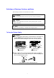
Definitions of Warnings, Cautions, and Notes The following conventions are used in this User’s Guide: Warning Indicates warnings that must be observed to prevent possible personal injury. ! Caution Indicates cautions that must be observed to use the printer properly or prevent damage to the printer. ✒ Note Indicates notes and useful tips to remember when using the printer.
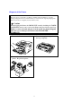
Shipment of the Printer If for any reason you must ship your Printer, carefully package the Printer to avoid any damage during transit. It is recommended that you save and use the original packaging. The Printer should also be adequately insured with the carrier. ! Caution When shipping the Printer, the DRUM UNIT assembly including the TONER CARTRIDGE must be removed from the Printer and placed in the plastic bag.
(For USA & CANADA Only) For technical and operational assistance, please call: In USA 1-800-276-7746 (outside California) 949-859-9700 Ext. 329 (within California) In CANADA 1-800-853-6660 514-685-6464 (within Montreal) If you have comments or suggestions, please write us at: In USA Printer Customer Support Brother International Corporation 15 Musick Irvine, CA 92718 In CANADA Brother International Corporation (Canada), Ltd. - Marketing Dept.
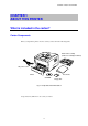
CHAPTER 1 ABOUT THIS PRINTER CHAPTER 1 ABOUT THIS PRINTER What is included in the carton? Carton Components When you unpack the printer, check to see that you have all of the following items: Drum unit assembly (with toner cartridge included) AC power cord Printer Documents CD-ROM Floppy disk Fig. 1-1 Components in the Printer Carton Components may differ from one country to another.
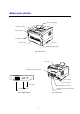
About your printer Face down output tray Tray extension flap Manual feed slot Control panel Paper cassette Front cover Manual feed paper guides Fig. 1-2 Front View Rear cover Modular jack for lower tray unit 10/100BASE TX LFA TEST Power switch AC power inlet Test button Parallel Interface connector LED USB (Universal Serial Interface Bus) connector 10/100Base TX port Fig. 1-3 Network Board Fig.
CHAPTER 1 ABOUT THIS PRINTER Features of your printer ❏ High Resolution and Fast Printing Speed True 600 x 600 dots per inch (dpi) and 1200 x 600 dpi for graphics with microfine toner and up to 12 pages per minute (ppm) print speed (A4 or Letter paper). ❏ Front Operation Basic operation of the printer can be done from the front of you.. ❏ Versatile Paper Handling This printer loads paper automatically from the paper cassette. The paper cassette can hold A4, letter, B5, Executive, A5 and A6 size paper.
❏ Enhanced Printing Performance and User-Friendly Operation for Windows® ® ® ® The dedicated printer drivers for Microsoft Windows 95/98, Windows 3.1x and ® Windows NT 4.0 are available on the CD-ROM supplied with your printer. You can ® easily install them into your Windows system using our installer program.
CHAPTER 1 ABOUT THIS PRINTER ❏ USB Interface (For Windows® 98, iMac and Power Macintosh G3 Using USB) This printer can be connected using the USB (Universal Serial Bus) Interface to a PC or Mac that has a USB interface. Drivers that allow you to use the USB port are provided on the CD-ROM supplied with the printer. ❏ High Resolution Control & Advanced Photoscale Technology High resolution control (HRC) technology provides clear and crisp printouts. Use this function to get smooth text print quality.
❏ Network Ready The Brother printer has built in multi protocol network capability as standard. This allows multiple host computers to share the printer on a 10/100Mbit Ethernet network. Any user can print their job as if the printer was directly connected to their computer. Users on Windows 95/98, Windows NT, Unix, Novell, Apple Macintosh, LAN server and OS/2 Warp server computer can simultaneously access this printer. For further information, please refer to the ‘Network manual’ supplied with the printer.
CHAPTER 1 ABOUT THIS PRINTER ❏ Remote Printer Console Program for DOS The Remote Printer Console (RPC) utility program is available on the CD-ROM supplied with your printer. When you operate your computer in a DOS (Disk Operating System) environment, this RPC program allows you to easily change the default settings of the printer such as fonts, page setup, and emulations. This RPC program also provides a status monitor program, which is a Terminate-and-Stay Resident (TSR) program.
What are the available printer options? Lower Tray Unit (LT-400) A lower tray unit expands the paper source capacity. You can load extra paper and switch between the upper and lower paper cassette automatically. See “The Lower Tray Unit” in Chapter 2. ❏ SIMM (Memory) The printer has 4.0 Mbytes of standard memory and one slot for optional additional memory. The memory can be expanded up to 36 Mbytes by installing a commercially available single in-line memory modules (SIMM).
CHAPTER 1 ABOUT THIS PRINTER Choosing a location Please take note of the following before using the printer. Power Supply • Use the printer within the specified power range. AC power: ±10% of the rated power voltage in your country Frequency: 50 Hz (220 V– 240 V) or 50/60 Hz (110–120 V) Check the rating plate on the back of the printer for your model’s specification. • The power cord, including extensions, should not exceed 5 meters (16.5 feet).
System Requirements for the Brother Printing Solution for Windows® The following tables list the system requirements needed to setup and the printer using the ® Brother Printing Solution for Windows : • IBM PC or compatible with 80486 SX or higher microprocessor • 10 MB of space available on your hard disk for the printer driver and all fonts ® ® ® • Microsoft Windows 3.1/3.11, Windows 95/98 or Windows NT 4.
CHAPTER 1 ABOUT THIS PRINTER What kind of paper can I use? Media Type Paper Cassette (standard) Manual feed sFeed Slot Paper type Cut Sheet Transparency Cut sheet Envelope Organizer Transparencies Labels Other Sizes Optional Lower Paper Cassette Cut Sheet Paper size letter, A4, ISO B5, Executive, A5, A6, legal (US and Canada Only) and A4 and letter letter, A4, B5 (JIS/ISO), Executive, A5, A6, legal COM 10, Monarch, C5, DL and ISO B5 ® Day-Timer J, K, L A4, Letter A4, Letter 70-216 x 116-356 mm, 2.
Note • We recommend that you use only labels or transparencies that are designed for laser printer use. • To avoid damage to the printer, the printing speed may change for the paper size you are using. Paper Capacity Upper Paper Cassette A4/Letter paper: Approx. 250 sheets of 80 g/m Transparency 10 sheets 2 Up to 27 mm (1.06 inches) in height (up to the mark) Output tray (printed pages are face down) A4/Letter paper: Approx.
CHAPTER 1 ABOUT THIS PRINTER Remarks We recommend that you test paper on this printer before purchasing large quantities, especially paper of a special type, size or thickness. Avoid using coated paper, for example, vinyl coated paper. Avoid using preprinted or highly textured paper. For optimum print quality, use only the recommended type of paper, especially when using plain paper or transparencies.
Special Paper To avoid paper jams and misfeeds when using paper with punched holes (for example, organizer sheets), fan the paper well. Do not use organizer sheets that are stuck together. The glue that is used may cause damage to the printer. Before using any paper, make sure that it is not curled. If it is curled, straighten the paper as much as possible. Feeding curled paper can cause paper jams and misfeeds. Fig.
CHAPTER 1 ABOUT THIS PRINTER Envelopes The following types of envelopes are not recommended. _ _ _ _ _ _ _ _ _ _ Damaged, curled, wrinkled, or irregularly shaped envelopes Extremely shiny or highly textured envelopes Envelopes with clasps Envelopes with self-adhesive closures Envelopes of baggy construction Envelopes not sharply creased Embossed envelopes Envelopes already printed by a laser printer Envelopes pre-printed on the inside Envelopes that cannot be arranged uniformly when placed in a pile Fig.
How to load paper in the Paper Cassette 1. Pull the paper cassette completely out of the printer. Fig. 1-8 Pull out the paper cassette 2. Slide the width and length paper guides to fit the size of paper you want to load. Make sure the tip of the paper guides fit into the slots correctly. Fig.
CHAPTER 1 ABOUT THIS PRINTER 3. Load paper into the paper cassette. Make sure that the paper is flat in the cassette in all four corners. Fig. 1-10 Load the paper Note 2 Do not load more than 250 sheets of paper (80 g/m ) in the cassette, or paper jams may occur. Paper can be loaded up to the maximum paper height guide. Fig.
4. Slide the paper cassette into the printer until it locks into place. Note • Unfold the output tray extension to prevent the paper from sliding off the front output tray. Fig. 1-12 Unfold the output tray extension • If you choose not to use the output tray extension, we recommend that you remove printed pages immediately they exit the printer. ! Caution Remove each sheet immediately especially when you use special paper such as transparencies. Fig.
CHAPTER 1 ABOUT THIS PRINTER How to use the Manual Feed Slot Note • Use both hands to insert the paper into the manual feed slot. • When you insert paper into the manual feed slot, the printer turns on the manual feed mode. • We recommended you use the paper cassette when you are using paper that is between A4 2 2 and A6 in size and between 64 g/m and 105 g/m . You can also view the technique of manually loading one sheet of paper at a time in the instructional video on the supplied CD-ROM. 1.
Fig. 1-14 Select manual feed mode 2. Send the print data to the printer. Note A “NO PAPER” message is shown in the Status Monitor until you insert a sheet of paper into the manual feed slot.
CHAPTER 1 ABOUT THIS PRINTER 3. Use both hands to slide the manual feed slot paper guides to the paper width to be used. Fig. 1-15 Set the width of the manual feed slot paper guides 4. Using both hands, insert the paper into the manual feed slot until the front edge of the paper touches the paper feed roller. Hold the paper in this position until the printer feeds in the paper a short distance, then let go of the paper. Fig. 1-16 Insert the paper 5.
To print on thicker paper and card stock When you rear cover is lifted up, the printer has a straight paper path from the manual feed slot to the rear of the printer. Use this paper feed and output method when you want to print on thicker paper or card stock. ☛ 1. Select manual feed mode in the printer driver. ☛ 2. Lift up the rear cover at the rear of the printer. Fig. 1-17 Lift up the rear cover ☛ 3. Send the print data as usual.
CHAPTER 1 ABOUT THIS PRINTER 4. 5. 6. 7. Use both to slide the manual feed slot paper guides to the paper width be used. Using both hands, insert the paper into the manual feed slot until the front edge of the paper touches the paper feed roller. Hold the paper in this position until the printer feeds in the paper a short distance, then let go of the paper. After the printer ejects the printed page, repeat Step 5 for each sheet of paper you want to print. Close the rear cover of the printer.
How to print on both sides of the paper (Manual Duplexing) ® ® ® The supplied printer drivers for Windows 95/98, Windows 3.1x and Windows NT 4.0 all enable manual duplex printing. For more information about how to make the settings, see the Help text in the printer driver. Guidelines for printing on both sides of the paper 1 It may cause wrinkling if the paper is too thin. 2 If paper is curled, straighten it and then place it in the paper cassette. 3 The paper type should be regular paper.
CHAPTER 1 ABOUT THIS PRINTER To print on both sides of the paper from the paper cassette 1. Select the required manual duplex printing mode from the driver. 2. The printer automatically will print all the even numbered pages on one side of the paper first. 3. Remove the printed even numbered pages from the output tray and re-insert them into the paper cassette, loading the paper with the side to be printed (blank side) face down, and the top edge toward you.
To print on both sides of the paper from the manual feed slot ! Caution • Before re-inserting the sheets, straighten them, or you may get paper feed errors. • The use of very thin or very thick paper is not recommended. • When you use the Manual Duplex function, it is possible that paper jams may occur or print quality may not be satisfactory. If a paper jam occurs, please see to “PAPER JAMS and how to clear them” in Chapter 4. 1. 2. 3.
CHAPTER 1 ABOUT THIS PRINTER What do the LED indications mean? This section refers to the LED and button on the printer control panel. The LED indications shown in the table below are used in the illustrations in this chapter. ❍ LED is Off LED is Blinking LED is On Drum Ready Paper Alarm Toner Data Fig. 1-21 LEDs and Button on the Control Panel ✒ Note When the power switch is off or the printer is in sleep mode, all LEDs including the Ready LED will be off.
Ready (Paper) LED indications The Ready LED indicates the current status of the printer. LED Off ❍ Blinking On Printer status The power switch is off or the printer is in sleep mode. If the printer is in sleep mode, it will wake up automatically when it receives data or when you press the control panel button. (Blinking at 1 second intervals) The printer is warming up. (Blinking at 2 seconds intervals) The printer is cooling down and stops printing until the internal temperature of the printer is lower.
CHAPTER 1 ABOUT THIS PRINTER Data (Toner) LED indications The Data LED indicates the current status of the print data process. LED Off ❍ Blinking On Printer status The printer has no print data. The printer is receiving data from the computer or the printer is processing data in memory. Print data remains in the printer memory. If the Data LED is on for a long period of time and nothing has printed, press the button to print the remaining data.
This LED also works as the Toner LED when the Alarm LED is also lit. They will blink simultaneously to indicate a toner error. See “How to replace the Toner cartridge” in Chapter 3. LED Error Toner low Action Indicates that the toner cartridge is nearly empty. Purchase a new toner cartridge and have it ready for when Toner empty is indicated. Toner empty Replace the toner cartridge with a new one. See “How to replace the Toner Cartridge” in Chapter 3.
CHAPTER 1 ABOUT THIS PRINTER Drum LED indications The Drum LED indicates the drum unit is nearly at the end of its life. LED Printer status The drum unit can be used. ❍ ● The drum unit is near the end of its life. Purchase a new drum unit to replace the current one. See “How to replace the drum unit” in Chapter 3. Alarm LED indications The Alarm LED blinks (with no other LEDs) to indicate a printer error status such as “COVER OPEN” or “MEMORY FULL.
Control Panel Button Operations The control panel button is used for the following purposes depending on the situation. Cancel Printing If you press the button during printing, the printer immediately stops printing and ejects the paper. Wake-Up If the printer is in sleep mode, pressing the button wakes it up into the Ready mode. It will take up to 45 seconds for the printer to go into the Ready mode. Form Feed If the Data LED is on, press the button.
CHAPTER 1 ABOUT THIS PRINTER More Features The printer has the following useful features: Sleep Mode When the printer does not receive data for a certain period of time (timeout), it enters sleep mode. Sleep mode acts as though the printer was turned off. The default timeout is 5 minutes, it is automatically adjusted to the most suitable time-out setting depending on the frequency of your printer use (Intelligent Sleep Mode).
Test Print Mode The printer has the following test print modes. Follow these steps: ☛ 1. Make sure that the front cover is closed. ☛ 2. Hold down the control panel button and turn on the power switch. Keep the button depressed until the Drum LED comes on. The Drum LED illuminates to indicate that the printer is in the test print mode. ☛ 3.
CHAPTER 2 OPTIONS CHAPTER2 OPTIONS Optional Accessories and Supplies This printer has the following optional accessories and supplies, and you can increase the capabilities of the printer with these items.
The Lower Tray unit The lower tray unit is an optional device that functions as a third paper source. It can hold a 2 maximum of 250 sheets of paper (80 g/m ). To purchase the optional lower tray unit, please see the dealer or store where you purchased the printer. Fig. 2-1 Loading Paper in the Lower Tray Unit With the lower tray unit installed, load paper in the lower paper cassette in exactly the same way that you load paper in the upper paper cassette.
CHAPTER 2 OPTIONS How to add extra Memory This printer has 4 Mbytes of standard memory and a slot for optional additional memory. The memory can be expanded up to a total of 36 Mbytes by installing a commercially available single in-line memory module (SIMM). Additional memory is useful and may be necessary if you are using the Page Protection function. It will also help if you are printing a page that is complex or at high resolution or is a complex PostScript Document.
How to install additional SIMM memory To install the SIMM, follow these steps: ☛ 1. Turn off the power switch and unplug the AC cord from the AC outlet. Disconnect the cable from the printer. Fig.
CHAPTER 2 OPTIONS ! Caution Be sure to turn off the power switch and unplug the AC cord to the printer before installing or removing the SIMM to/from the main controller PCB. ☛ 2. Open the Rear Paper exit cover. Unscrew the screws securing the access cover and remove it. Fig. 2-3 Removing the Main Controller PCB ☛ 3. Unscrew the network board securing screws and remove it. Fig.
☛ 4. Unpack the SIMM and hold it by its edge. ! Caution SIMM boards may be damaged by even a small amount of static electricity. Do not touch the memory chips or the board surface. When handling the board and before installing or removing it, wear an antistatic wrist strap, or frequently touch the surface of the antistatic package or bare metal on the printer. ☛ 5. Install the SIMM into the slot at an angle and then gently push it toward the vertical until it clicks into place. Fig.
CHAPTER 3 MAINTENANCE CHAPTER3 MAINTENANCE The following are maintenance messages that appear on the LEDs. These messages prompt you to replace each of the consumables before they run out.
Periodic maintenance parts To maintain print quality, the parts listed below should be replaced after printing the following number of pages.
CHAPTER 3 MAINTENANCE How to replace the Toner Cartridge When the Standard Capacity toner cartridge is used, the printer can print approximately 3,000 pages at 5% coverage on A4/Letter size paper with one toner cartridge. When the High Capacity toner cartridge is used, approximately 6,000 pages can be printed under the same conditions. When the toner cartridge is running low, the Alarm and Data (Toner) LEDs blink once every 5 seconds to indicate the toner is depleted and will soon run out.
✒ Note Both Alarm and Data (Toner) LEDs will blink continuously to indicate that the toner is nearly empty. This blinking does not stop until you have installed a new toner cartridge. The toner cartridge is replaced in the following way. You can also view the toner cartridge replacement method in the instructional video on the supplied CD-ROM: ☛ 1. Open the front cover. Pull out the drum unit assembly. Fig.
CHAPTER 3 MAINTENANCE ☛ 2. Place the drum unit assembly on a piece of cloth or disposable paper that is on a flat, horizontal surface. Pull the toner cartridge out of the drum unit assembly while holding down the lock lever with your right hand. Hold down this Lock Lever. Fig. 3-4 Removing the old toner cartridge ! Caution Handle the toner cartridge carefully. If toner scatters on your hands or clothes, immediately wipe or wash it off with cold water. ☛ 3. Unpack the new toner cartridge.
☛ 4. Remove the protective cover. Fig.3-6 Remove the protective cover ! Caution Wait to unpack the toner cartridge until immediately before you are ready to install it into the printer. If toner cartridges are left unpacked for a long period of time, the toner life is shortened. If an unpacked drum unit is subjected to excessive direct sunlight or room light, the unit may be damaged. Use only a genuine Brother toner cartridge which is specially formulated to ensure top print quality.
CHAPTER 3 MAINTENANCE ☛ 5. Install the new toner cartridge into the drum unit until it clicks into place. When the toner cartridge is installed correctly, the lock lever is lifted and locks automatically. This Lock Lever is up until this position. X Fig. 3-9 Installing the toner cartridge into the drum unit ! Caution Make sure the toner cartridge is installed correctly, or the toner cartridge may separate from the drum unit when you hold the drum unit assembly.
☛ 6. Clean the primary corona wire inside the drum unit by gently sliding the blue tab to the right and the left ends several times. Return the tab to the Home position before reinstalling the drum unit assembly. Home Position (▲) Fig. 3-10 Cleaning the primary corona wire ! Caution Make sure that you return the tab to the home position (▲ mark position) before reinstalling the drum unit assembly into the printer otherwise printed pages may have vertical stripes. ☛ 7.
CHAPTER 3 MAINTENANCE How to replace the Drum Unit The printer uses a drum unit to create the print images on paper. If the Drum LED is lit it indicates the drum unit is near the end of its life. Purchase a new drum unit to replace the current one. Even if the Drum LED is on, you may be able to continue to print without replacing the drum unit for a while. However, if there is a noticeable deterioration in the output print quality even before the Drum LED lights, then the drum unit should be replaced.
You can also view the drum unit replacement method in the instructional video on the supplied CD-ROM. Follow these steps to replace the drum unit. ☛ 1. Open the front cover of the printer and pull out the drum unit assembly. Fig. 3-13 Removing the drum unit assembly ! Caution To prevent damage to the printer caused by static electricity, do no touch the electrodes shown below.
CHAPTER 3 MAINTENANCE ☛ 2. Place the drum unit assembly on a piece of cloth or disposable paper that is on a flat, horizontal surface. Pull the toner cartridge out of the drum unit assembly while holding down the lock lever with your right hand. Hold down this Lock Lever. Fig. 3-15 Removing the toner cartridge ✒ Note Discard the used drum unit according to local regulations. If you are not sure of them, consult your local dealer/retailer.
☛ 4. Install the toner cartridge into the new drum unit until it locks into place, indicated by a click. When the toner cartridge is installed correctly, the lock lever is lifted automatically. ! Caution Make sure that the toner cartridge is installed correctly, or the toner cartridge may separate from the drum unit when you hold the drum unit assembly. This Lock Lever is up until this position. X Fig. 3-16 Install the toner cartridge into the drum unit ☛ 5.
CHAPTER 3 MAINTENANCE ☛ 6. Make sure the printer is turned on, the front cover is open and the Drum and Alarm LEDs are illuminated. ☛ 7. Reset the page counter. See the instructions supplied with the new drum unit. ! Caution When you replace only the toner cartridge, do not reset the page counter. ☛ 8. Close the front cover. ☛ 9. Make sure that the Drum LED is now off.
How to clean the printer Clean the printer exterior and interior periodically. If printed pages get stained with toner, clean the printer interior and drum unit. Cleaning the printer exterior ✒ Note Clean the printer exterior using the information in the following instructions. This procedure is demonstrated in the instructional video on the supplied CD-ROM. ☛ 1. Turn off the power switch and unplug the power cord. Warning There are high voltage electrodes inside the printer.
CHAPTER 3 MAINTENANCE ! Caution Use water or neutral detergents for cleaning. Cleaning with volatile liquids such as thinners or benzene will damage the surface of the printer. ☛ 3. Wipe dirt and dust away from the printer exterior with the damp cloth and allow the printer to dry completely before turning the power on again. ☛ 4. Plug in the power cord.
Cleaning the printer interior and Drum Unit ✒ Note Clean the printer interior and the drum unit following the instructions below. You can view this procedure in the instructional video on the supplied CD-ROM. ☛ 1. Turn off the power switch and unplug the power cord. Warning There are high voltage electrodes inside the printer. Before cleaning the printer, make sure you have turned off the power switch and unplugged the power cord from the outlet. Fig.
CHAPTER 3 MAINTENANCE Warning After you have just used the printer, some internal parts of the printer are extremely HOT. When you open the front cover of the printer, never touch the shaded parts shown in the following illustration. High Temperature High Temperature Front view Rear view Fig. 3-20 Inside the printer ☛ 4. Gently wipe the scanner window with a soft dry cloth. Scanner Window Fig. 3-21 Cleaning the scanner window ! Caution Do not touch the scanner window with your fingers.
☛ 5. Clean the primary corona wire inside the drum unit by gently sliding the tab to the right hand end and left hand end several times. Home Position (▲) Fig. 3-22 Cleaning the primary corona wire ☛ 6. Return the tab to the Home position before reinstalling the drum unit assembly into the printer. ! Caution Be sure to position the tab at the Home position, or printed pages may have vertical stripes. ☛ 7. Install the drum unit assembly into the printer.
CHAPTER 4 TROUBLESHOOTING CHAPTER4 TROUBLESHOOTING Identifying your problem First, check the following: • • • • • • • • The power plug is connected correctly and the printer is turned on. All of the protective parts have been removed. The toner cartridge and drum unit are installed correctly. The Front Cover is completely closed. Paper is loaded correctly in the paper cassette. The interface cable is securely connected between the printer and computer.
Control Panel Indications Operator calls and how to clear them The LED indications as shown in the table below are used in the illustrations in this chapter. ❍ LED is Off LED is Blinking LED is On If a recoverable error occurs, the printer indicates an ‘operator call’ by the LED indications as shown in the table below. Identify the error from the table below and take the action described for each indication to correct it.
CHAPTER 4 TROUBLESHOOTING LED Error Paper jam Action Clear the paper jam. See the next section “PAPER JAMS and how to clear them”. Press the panel button if the printer does not automatically resume printing. No paper Load paper into the printer . See Chapter 1, then press the panel button. Misfeed Reinstall the paper and press the panel button. Indicates that the toner cartridge is nearly empty. Purchase a new toner cartridge and have it ready for when Toner Empty status is indicated.
Service call indications If an unrecoverable error occurs, the printer will indicate the need for a service call by illuminating all the LEDs, followed by a combination of LEDs as shown below: For example, the following are the indications when a Fuser malfunction error occurs. Drum Drum Ready Paper Alarm Toner Data Ready Paper Alarm Toner Data Fig.
CHAPTER 4 TROUBLESHOOTING If you see any of these service call indications, turn off the power switch, wait a few seconds, then turn it on and try to print again. If you cannot clear the error and see the same service call indication after turning on the printer, consult your dealer or our authorized service representative. Please note the indication and report the error status and problem by referring to the above table.
Error Messages in the Status Monitor The Status Monitor will report problems with the printer as defined in the following table. Take the corrective actions for the error message that is suggested in the Status Monitor reports. Error Message COVER OPEN NO PAPER or MISFEED PAPER JAM TONER LOW TONER EMPTY PRINT OVERRUN Action • Close the front cover of the printer. • The paper cassette may be out of paper or not properly installed. If it is empty, load a new stack of paper into the paper cassette.
CHAPTER 4 TROUBLESHOOTING Error Message MEMORY FULL RESOLUTION ADAPTED (The printer has printed the document at a reduced resolution.) FUSER MALFUNCTION LASER BD MALFUNCTION SCANNER MALFUNCTION D-RAM ERROR NV-RAM ERROR MAIN MOTOR ERROR ENGINE INTERFACE ERROR Action • Press the panel button to print the data remaining in the printer. • Reduce the print resolution or reduce the complexity of your document. • Expand the printer memory by adding a commercially available SIMM.
Error Message Printouts The printer will report problems by printing an error message as defined in the following table. Take the corrective actions for the error message the Printout reports. Error Message MEMORY FULL PRINT OVERRUN RESOLUTION ADAPTED (The printer has printed the document at a reduced resolution) Action • Press the panel button to print the data remaining in the printer. • Reduce the print resolution or reduce the complexity of your document.
CHAPTER 4 TROUBLESHOOTING Paper Handling First, ensure that you are using paper that meets Brother recommended paper specifications. See “What kind of paper can I use” in Chapter 1. Problem The printer does not load paper. The printer does not feed paper from the manual feed slot. The printer will not feed envelopes. A paper jam has occurred. The printer does not print to the output tray. The printer does not print on the specified paper.
PAPER JAMS and how to clear them When a paper jam occurs, the printer notifies you by illuminating the LEDs as shown below. Drum Ready Paper Alarm Toner Data Fig. 4-3 LED indication caused by a paper jam Warning After you have just used the printer, some internal parts of the printer are extremely HOT. When you open the front or rear cover of the printer, never touch the shaded parts shown in the following diagram.
CHAPTER 4 TROUBLESHOOTING Clear the jammed paper. See the following instructions or view the paper jam instructional video on the CD-ROM. If the jammed paper is removed completely by using these steps, you can close the paper cassette first, then close the front cover. The printer should resume printing. If the printer does not resume printing automatically, press the control panel button.
2. Pull any jammed paper up and out of the printer. Fig. 4-6 Pull the jammed paper up and out 3. Open the front cover.
CHAPTER 4 TROUBLESHOOTING 4. Remove the drum unit assembly. Pull any jammed paper up and out of the printer. Do not use additional force to remove the drum unit assembly if you cannot remove it easily. Instead, pull the edge of the jammed paper from the paper cassette. Fig. 4-7 Remove the drum unit assembly Fig.
! Caution To prevent damage to the printer caused by static electricity, do not touch the electrodes shown below. Fig. 4-9 Electrodes 5. Open the rear cover and pull the jammed paper out of the fuser unit. If you have to pull the paper toward the back of the printer, the fuser may get dirty with toner powder and may result in scattered toner on the next printed page or pages. Print a few copies of the test page until the toner scatter on the printed pages stops. Fig.
CHAPTER 4 TROUBLESHOOTING Other Problem The printer cannot print. “There was an error writing to LPT1: (or BRUSB) for the printer.” error message appears on your PC. Recommendation • Check that the printer cable is not damaged or broken. • If you have an interface switching device, make sure the correct printer is selected. For DOS users Problem Unable to print from application software.
For Apple Macintosh Computers user Problem Unable to print from application software. Recommendation • Make sure the supplied Macintosh printer driver is installed in the System Folder and it is selected with Chooser. • Check the PORT selection within the Chooser : it should match the port to which you physically attached the printer cable. • Check the printer cable type : you cannot use a Local Talk or straight-through cable.
CHAPTER 4 TROUBLESHOOTING Improving the print quality ! Caution If the Drum LED is lit you can clear a print quality problem by replacing the drum unit with a new one. The Drum LED indicates that the drum unit is at the end of life. This section provides information on the following topics: Image defect examples ABCDEFGH CDEF abcdefghijk defg ABCD abcde 01234 Faint ABCDEFGH abcdefghijk ABCD abcde 01234 Gray background Recommendation • Check the printer's environment.
Image defect examples ABCDEFGH abcdefghijk ABCD abcde 01234 Recommendation • Make sure that you use paper that meets the specifications. A rough surfaced paper may cause the problem. See “What kind of paper can I use” in Chapter 1. • The drum unit may be damaged. Install a new drum unit. See "How to replace the Drum unit" in Chapter 3. Toner specks • • • Make sure you use paper that meets the specifications. See “What kind of paper can I use” in Chapter 1.
CHAPTER 4 TROUBLESHOOTING Image defect examples 94 mm (3.7 in.) 94 mm (3.7 in.) Recommendation • If the problem is not solved after printing a few pages, the drum unit may have glue from label stock on the OPC drum surface. Clean the drum unit as follows 1. Position the print sample in front of the drum unit, and find the exact position of the image defect. White Spots Printed pages have white spots in black text and graphics at intervals of 94 mm. 94 mm (3.7 in.) 94 mm (3.7 in.) Fig.
Image defect examples Recommendation ! Caution Do not try to clean the surface of the photosensitive drum with anything sharp such as a ball-point pen etc. 94 mm (3.7 in.) 94 mm (3.7 in.) • The drum unit may be damaged. Install a new drum unit. See “How to replace the Drum unit” in Chapter 3. White Spots Printed pages have white spots in black text and graphics at intervals of 94 mm. 94 mm (3.7 in.) 94 mm (3.7 in.) Printed pages have black spots at intervals of 94 mm.
CHAPTER 4 TROUBLESHOOTING Image defect examples ABCDEFGH abcdefghijk ABCD abcde 01234 Black Horizontal repetitive defects Toner scatters and stains the printed page. ABCDEFGH abcdefghijk ABCD abcde 01234 White horizontal stripes Recommendation • The drum unit may be damaged. Install a new drum unit. See "How to replace the Drum unit" in Chapter 3. • Make sure you use paper that meets specifications. See “What kind of paper can I use” in Chapter 1.
Image defect examples . ABCDEFGH abcdefghijk ABCD abcde 01234 Recommendation • You may clear the problem by wiping the scanner window with a soft cloth. See “How to clean the printer” in Chapter 3. • The toner cartridge may be damaged. Install a new toner cartridge. See "How to replace the Toner cartridge" in Chapter 3.
CHAPTER 4 TROUBLESHOOTING How to print correctly Problem The printer prints unexpectedly or it prints garbage data. The printer cannot print full pages of a document. An error message “PRINT OVERRUN” occurs. The printer cannot print full pages of a document. A "MEMORY FULL" error message occurs. My headers or footers appear when I view my document on screen but do not show up when I print them. Recommendation • Make sure the printer cable is not too long.
For DOS users Problem The printer prints, but it prints incorrect information. Sometimes it prints a couple of characters and then ejects the page, etc. Recommendation • This is an indication that your application printer emulation setting and the printer’s emulation do not match. Check in your application software which printer you have selected to make sure the printer is set up correctly.
APPENDIX APPENDIX Printer Technical Specifications Printing Print Method Electrophotography by semiconductor laser beam scanning Laser Wavelength: Output: 780 nm 5 mW max 1200 (H) x 600 (V) dots/inch ® (for Windows DIB graphics) Resolution 600 (H) x 600 (V) dots/inch ® (for Windows and DOS) Print Quality Normal printing mode Economy printing mode (up to 25% and 50% toner saving) Print Speed Up to 12 pages per minute When A4 or letter-size paper is loaded from the paper cassette.
Print Media Toner cartridge: 3,000 pages/standard capacity toner cartridge 6,000 pages/high capacity toner cartridge (When printing A4- or letter-size paper at 5% print coverage.) Life Expectancy: NOTE: Toner life expectancy will vary depending on the type of average print job printed.
APPENDIX Functions TrueType Fonts on CD TrueType-compatible soft-fonts for Windows are provided on the supplied CD. Quantity of fonts is 35. Emulation Brother Printing Solution for Windows Automatic emulation selection among HP LaserJet6P (PCL 6), Brother BRScript Level 2, EPSON FX-850 or IBM Proprinter XL. Printer Driver PCL driver: Windows 3.1/3.11, Windows 95/98 and Windows NT 4.0 driver, supporting Brother Native Compression mode ® ® Windows 3.1/3.
Electrical and Mechanical Power Source USA and Canada: Europe and Australia: AC 110 to 120 V, 50 / 60 Hz AC 220 to 240 V, 50 /60 Hz Power Consumption Printing (average): 340 W or less Stand-by: Sleep 80 W or less 12 W or less Noise Printing: Sleep: 49 dB A or less 27 dB A or less Temperature Operating: Storage: 10 to 32.5°C (50 to 90.
APPENDIX Parallel Interface Specifications ✒ Note • To ensure best quality performance use an IEEE 1284 compliant parallel cable between the printer and your computer. Only IEEE 1284 cables support all of the advanced printing capabilities, such as bi-directional communication. These cables will be clearly marked with “IEEE-1284”. • We recommend that you use a parallel cable that is 2.0 meters (6.6 feet) or less.
✒ Note To use bi-directional communication, you must set up an interface cable that has the pin connections listed above. Pin 1 18 2 19 3 Pin 1 19 2 20 3 21 4 22 5 23 6 24 7 25 8 26 9 27 10 28 11 29 12 17 13 15 14 30 31 33 32 34 36 35 18 16 4 20 5 6 21 7 8 22 9 10 24 11 23 12 13 14 25 16 15 17 Shield Shield Fig.
APPENDIX USB (Universal Serial Bus) Interface Universal Serial Bus (USB) Interface 2 1 4 3 Fig. A-2 USB interface connector Pin Assignment Pin No.
Network Interface Network Interface 1 3 5 4 2 6 7 8 Fig. A-3 10/100Base TX Port Pin Assignment RJ45 pin 1 TX+ 2 TX− 3 RX+ 4 5 6 RX− 7 8 Signal Transmit Data + Transmit Data − Receive Data + N.C. N.C. Receive Data − N.C. N.C. For more information, see the “Network User’s Guide” on the CD-ROM.
APPENDIX Emulation Modes This printer has the following emulations modes: HP LaserJet Mode This printer uses the HP LaserJet mode (or HP mode) that emulates the HewlettPackard LaserJet laser printer. Since many application software packages support the HP LaserJet printer, your printer will operate at its optimum performance in this mode. ■ BR-Script 2 Mode BR-Script is a Brother original page description language and is a PostScript ® language emulation interpreter. This printer supports level 2.
Resident Fonts The following bitmapped fonts are resident in this printer. Bitmapped Fonts This printer has the following bitmapped fonts. They can be used in the HP LaserJet 6P, EPSON FX-850, and IBM Proprinter XL modes. They have the following characteristics. • • • Letter Gothic 16.
APPENDIX Scalable Fonts The following scalable fonts can be used in the HP LaserJet 6P, EPSON FX-850 and IBM Proprinter XL modes. 75 Scalable and 12 Bitmapped Fonts This printer has the following scalable fonts and bitmapped fonts. The fonts that can be used will vary according to the current emulation mode.
■ BR-Script 2 Mode Scalable Fonts: • Atlanta Book, BookOblique, Demi, DemiOblique • Alaska, Extrabold • Antique Oakland, Oblique, Bold • Bermuda Script • BR Dingbats • BR Symbol • Brougham, Oblique, Bold, BoldOblique • Brussels Light, LightItalic, Demi, DemiItalic • Calgary MediumItalic • Cleveland Condensed • Connecticut • Copenhagen Roman, Italic, Bold, BoldItalic • Germany • Guatemala Antique, Italic, Bold, BoldItalic • Helsinki, Oblique, Bold, BoldOblique • Helsinki Narrow, Oblique, Bold, BoldOblique •
APPENDIX Symbol Sets / Character Sets OCR Symbol Sets When the OCR-A or OCR-B font is selected, its corresponding symbol set is always used. • OCR-A • OCR-B • • • • • • • • • • • • • • • • Legal (1U) Ventura Math (6M) Ventura Intl (13J) Ventura US (14J) PS Math (5M) PS Text (10J) Math-8 (8M) Pi Font (15U) MS Publishing (6J) Windows 3.
EPSON Mode • • • • • • • • US ASCII PC-8 PC-8 D/N PC-850 PC-852 PC-860 PC-863 PC-865 • • • • • • • • PC-8 Turkish German UK ASCII I French I Danish I Italy Spanish Swedish • • • • • • • Japanese Norwegian Danish II UK ASCII II French II Dutch South African • • • PC-852 PC-860 PC-863 • • PC-865 PC-8 Turkish IBM Mode • • • PC-8 PC-8 D/N PC-850 ✒ Note If you want to know the characters that are available in each symbol/character set, print the CHARSETS.
APPENDIX ❏ HP LaserJet IIP / HP LaserJet 6P A-15
The following table shows characters available only in the corresponding character set. The numbers at the top of the table are code values with which characters are to be replaced in the Roman 8 character set. For other characters, see the Roman 8 character set.
APPENDIX ❏ HP LaserJet IIP/6P, EPSON FX-850, IBM Proprinter XL ❏ EPSON FX-850 A-17
The following table shows characters available only in the corresponding character set. The numbers at the top of the table are code values with which characters are to be replaced in the US ASCII character set. For other characters, see the US ASCII character set.
APPENDIX Trademarks The Brother logo is a registered trademark of Brother Industries, Ltd. Apple, the Apple Logo, and Macintosh are trademarks, registered in the United States and other countries, and TrueType is a trademark of Apple Computer, Inc. Epson is a registered trademark and FX-80 and FX-850 are trademarks of Seiko Epson Corporation. Hewlett Packard is a registered trademark and HP LaserJet 6P, 6L, 5P, 5L, 4, 4L 4P, III, IIIP, II, and IIP are trademarks of Hewlett-Packard Company.
REGULATIONS Federal Communications Commission(FCC) Declaration of Conformity (For USA Only) Responsible Party : Brother International Corporation 100 Somerset Corporate Boulevard Bridgewater, NJ 08807-0911, USA TEL : (908) 704-1700 declares, that the products Product Name : Brother Laser Printer HL-1240, HL-1250, HL-1270N Model Numbers : HL-12 Product Options : ALL complies with Part 15 of the FCC Rules.
APPENDIX Industry Canada Compliance Statement (For Canada Only) This Class B digital apparatus complies with Canadian ICES-003. Cet appareil numérique de la classe B est conforme à la norme NMB-003 du Canada. International ENERGY STAR Compliance Statement The purpose of the International ENERGY STAR Program is to promote the development and popularization of energy-efficient office equipments, which includes computers, monitors, printers, facsimile receivers and copy machines world-wide.
FDA Regulations (For 110-120 V Model Only) U.S. Food and Drug Administration (FDA) has implemented regulations for laser products manufactured on and after August 2, 1976. Compliance is mandatory for products marketed in the United States. One of the following labels on the back of the printer indicates compliance with the FDA regulations and must be attached to laser products marketed in the United States. MANUFACTURED: Brother Corporation (Asia) Ltd. Brother Buji Nan Ling Factory Gold Garden Ind.
APPENDIX IEC 825 Specification (For 220–240 V Model Only) This printer is a Class 1 laser product as defined in IEC 825 specifications. The label shown below is attached in countries where it is required. CLASS 1LASER PRODUCT APPAREIL Å LASER DE CLASSE 1 LASER KLASSE 1 PRODUKT This printer has a Class 3B Laser Diode that emits invisible laser radiation in the Scanner Unit. The Scanner Unit should not be opened under any circumstances.
IMPORTANT - For Your Safety To ensure safe operation the supplied three-pin electrical plug must be inserted only into a standard three-pin power point that is properly grounded through normal household wiring. Extension cords used with the equipment must be the three-pin plug type and correctly wired to provide proper grounding. Incorrectly wired extension cords may cause personal injury and equipment damage.
APPENDIX IMPORTANT - Wiring Information (For U.K. only) If the power cord supplied with this printer is not suitable for your electrical outlet, remove the plug from the mains cord and fit an appropriate three pin plug. If the replacement plug is intended to take a fuse then fit a fuse with the same rating as the original. If a moulded plug is severed from the power cord then it should be destroyed because a plug with cut wires is dangerous if plugged into a live socket outlet.
CHAPTER 2 OPTIONS INDEX interface............................................. A-3 -A- -L- advanced photoscale technology........ 1-5 Alarm lamp ........................................ 4-2 Alarm LED ...................................... 1-31 APT.................................................... 1-5 auto-emulation switching................... 1-4 LED.................................................. 1-27 LEDs ................................................ 1-27 lower paper cassette ................
-Qquick print setup................................. 1-4 -RReady LED ...................................... 1-28 resident font .................................... A-10 resolution ................................... 1-3, A-1 -Sscalable font .................................... A-11 scanner window ............................... 3-17 service call ......................................... 4-4 SIMM................................................. 2-3 sleep mode ................................