Brother Color Laser Printer HL-3450CN Series User’s Guide Version 0 Before you can use the printer, you must set up the hardware and install the driver. Please refer to the Quick Setup Guide while setting up the printer. Please read this manual thoroughly before using the printer. Keep the CD-ROM in a convenient place for quick and easy reference at all times. Please visit our user support web site, Brother Solutions Center, at http://solutions.brother.com.
Trademarks Brother is a registered trademark of Brother Industries, Ltd. Apple and LaserWriter are registered trademarks, and TrueType is a trademark of Apple Computer, Inc. Centronics is a trademark of Genicom Corporation. EPSON is a registered trademark, and FX-850 and FX-80 are trademarks of Seiko Epson Corporation.
B Brrootthheerr LLaasseerr P Prriinntteerr HL-3450CN Series User’s Guide (For USA & CANADA Only) IMPORTANT INFORMATION: For technical and operational assistance, you must call the country where you purchased the printer. Calls must be made from within that country.
DEEFFIINNIITTIIO ON NS SO OFF WA AR RN NIIN NG GS S, CA AU UTTIIO ON NS S, A AN ND D NO OTTE ES S The following conventions are used in this User’s Guide: ! Warning Indicates warnings that must be observed to prevent possible personal injury. ! Caution Indicates cautions that must be observed to use the printer properly or prevent damage to the printer. Note Indicates notes and useful tips to remember when using the printer.
! Warning HARMFUL OZONE GAS Inhalation of an excessive amount of ozone can adversely affect your respiratory system. An Ozone Filter is included to reduce ozone exhaust. This filter must be replaced periodically in accordance with the instructions found in your User’s Guide. ! Warning If the printer becomes hot, blows smoke, or generates obscure odor, turn the printer off immediately and unplug the printer. Contact your dealer.
! Warning In case of a fuser oil spill, you must clean it up immediately. ! Warning Do not put any pressure on the Feeder Cassette or the Front Cover when it is open. If you do, you injured because the printer fall on you.
PRRIINNTTEERR DO O'S SA AN ND D DO ON N'TTS S FFO OR R OP PTTIIM MU UM M PR RIIN NTT QU UA ALLIITTY Y ! Caution Before you move or lift the printer, remove the Toner Cartridges, Waste Toner Pack, Oil Bottle and Fusing Unit to avoid spills. Be sure to keep the printer as level as possible. Damage caused by failure to remove the supplies will void your warranty. ! Caution Do not touch the rollers of the Fusing Unit. This can degrade print quality.
TABLE OF CONTENTS TABLE OF CONTENTS CHAPTER 1 INTRODUCTION ABOUT THIS USER’S GUIDE 1-1 ABOUT THIS PRINTER Checking the Components General View Features Options Compact Flash Card RAM Operating and Storage Environment 1-3 1-3 1-5 1-6 1-12 1-13 1-13 1-13 CHAPTER 2 DRIVER AND SOFTWARE PRINTER DRIVER ® Features in the PCL Printer Driver (Windows 95/98/Me Users Only) ® Features in the PS printer driver (Windows 95/98/Me users only) Software for networks Software for Windows Computers Software for Macintosh
TABLE OF CONTENTS CHAPTER 4 CONTROL PANEL OPERATION CONTROL PANEL 4-1 BUTTONS Go button Job Cancel button Secure Print button Reprint button +, – buttons Set button Back button 4-2 4-3 4-3 4-4 4-5 4-13 4-13 4-14 LEDs 4-15 LCD DISPLAY LCD Messages Printer Status Messages 4-16 4-17 4-18 HOW TO USE THE CONTROL PANEL 4-19 PANEL SETup MENU 4-21 CHAPTER 5 MAINTENANCE REPLACING THE CONSUMABLES Toner Cartridges Oil Bottle Fuser Cleaner Waste Toner Pack OPC Belt Cartridge Ozone Filter Fusing Unit 120K K
TABLE OF CONTENTS CHAPTER 6 OPTIONS LOWER TRAY UNIT (LT-34CL) Loading Paper in the Lower Paper Cassette How to Install the Lower Tray Unit How to Clear Paper Jams in the Lower Tray Unit 6-1 6-1 6-1 6-6 DUPLEX UNIT (DX-3400) 6-7 COMPACTFLASH CARD / HARD DISK DRIVE (HD-6G/HD-EX) CompactFlash Card Hard Disk Drive (HD-6G / HD-EX) Selecting the Optional Fonts Installing a CompactFlash Card Installing a HDD (Hard Disk Drive) 6-11 6-11 6-12 6-12 6-15 6-16 RAM EXPANSION Installing DIMMs 6-18 6-19 CHAPTER 7
TABLE OF CONTENTS APPENDIX PRINTER SPECIFICATIONS Printing Functions Electrical and Mechanical A-1 A-1 A-2 A-3 PAPER SPECIFICATIONS Paper Envelopes Labels and Overhead Transparencies A-4 A-6 A-7 A-8 SYMBOL/CHARACTER SETS OCR Symbol Sets HP PCL Mode EPSON Mode IBM Mode HP-GL Mode Symbol Sets Supported by the Printer’s Intellifont Compatible Typefaces Symbol Sets Supported by the Printer’s TrueType™ and Type 1 Font Compatible, and Original Typefaces INDEX ix A-9 A-9 A-10 A-12 A-13 A-14 A-15 A-17
REGULATIONS IMPORTANT INFORMATION: REGULATIONS ELLEECCTTRRO ON NIIC C EM MIIS SS SIIO ON N NO OTTIIC CE ES S Federal Communications Commission (FCC) Compliance Notice (For U.S.A. Only) Responsible Party: Brother International Corporation 100 Somerset Corporate Boulevard Bridgewater, NJ 08807-0911, USA TEL: (908) 704-1700 declares, that the products Product Name: Model Number: Product Options: Brother Laser Printer HL-3450CN HL-3450CN ALL complies with Part 15 of the FCC Rules.
REGULATIONS Industry Canada Compliance Statement (For Canada Only) This Class B digital apparatus complies with Canadian ICES-003. Cet appareil numérique de la classe B est conforme à la norme NMB-003 du Canada. Declaration of Conformity (For Europe) We, Brother Industries, Ltd., 15-1, Naeshiro-cho, Mizuho-ku, Nagoya 467-8561, Japan declare that this product is in conformity with the following normative documents.
REGULATIONS Laser Notices Laser Safety (120 V Model Only) This printer is certified as a Class I laser product under the U.S. Department of Health and Human Services (DHHS) Radiation Performance Standard according to the Radiation Control for Health and Safety Act of 1968. This means that the printer does not produce hazardous laser radiation.
REGULATIONS IEC 60825 Specification (220 - 240 V Model Only) This printer is a Class 1 laser product as defined in IEC 60825 specifications. The label shown below is attached in countries where required. CLASS 1LASER PRODUCT APPAREIL Å LASER DE CLASSE 1 LASER KLASSE 1 PRODUKT This printer has a Class 3B Laser Diode that emits invisible laser radiation in the Scanner Unit. The Scanner Unit should not be opened under any circumstances.
REGULATIONS Safety Information IMPORTANT - For Your Safety To ensure safe operation the supplied three-pin plug must be inserted only into a standard three-pin power outlet that is properly grounded through the normal household wiring. Extension cords should not be used with the equipment. If it is essential that an extension cord has to be used, it must be a three-pin plug type and correctly wired to provide proper grounding.
REGULATIONS Wiring Information (For U.K. only) Important If the mains plug supplied with this printer is not suitable for your socket outlet, remove the plug from the mains cord and fit an appropriate three pin plug. If the replacement plug is intended to take a fuse then fit the same rating fuse as the original. If a moulded plug is severed from the mains cord then it should be destroyed because a plug with cut wires is dangerous if engaged in a live socket outlet.
CHAPTER 1 INTRODUCTION CHAPTER 1 INTRODUCTION
CHAPTER 1 INTRODUCTION ABOUT THIS USER’S GUIDE This manual acts as your guide for the setup and operation of your printer and covers the following topics: CHAPTER 1 INTRODUCTION provides an overview of the printer. Read this chapter first to become familiar with the printer. CHAPTER 2 DRIVER AND SOFTWARE gives you general information about the printer driver and the software. Be sure to read this chapter before you use the printer.
CHAPTER 1 INTRODUCTION Note When you read this User’s Guide, note the following: • This User’s Guide contains instructions or steps to teach you the various operations of the printer. Please remember that the instructions always assume that you started with the factory settings, particularly those in Chapter 2 and Chapter 3. If you change the settings, particularly the emulation mode, the display messages will change accordingly.
CHAPTER 1 INTRODUCTION ABOUT THIS PRINTER ! Warning This printer is heavy and weighs approximately 56kg (124 lbs). To avoid injury when moving or lifting this printer, be sure to use at least two people.
CHAPTER 1 INTRODUCTION Note An interface cable is not a standard accessory. Please purchase the appropriate cable for the interface you intend to use. Parallel cables should be IEEE 1284 compliant and should not exceed 1.8 metres (6 feet) in length. The power cord may differ slightly from this diagram, depending on the country where you purchased the printer. Note Depending on the country where you purchased and will use the HL-3450CN series model, you may have additional parts not listed above.
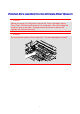
CHAPTER 1 INTRODUCTION GEENNEERRAALL VIIEEW W Top Cover Control Panel Power Button Front Cover Paper Cassette Fig. 1-2 Controller Box Rear Side Cover Rear Access Cover Power Cord Connector Fig.
CHAPTER 1 INTRODUCTION FEEAATTUURREESS This printer has the following standard features. 2400 DPI Class Resolution This printer prints at a default resolution of 600 dots per inch (dpi). You can achieve a higher print quality equivalent to 2400x600 dpi class resolution, by utilizing these Brother technologies: High Resolution Control (HRC) and Color Advanced Photoscale Technology (CAPT). High Speed and Color Laser Printing You can print crisp images in brilliant 24-bit color.
CHAPTER 1 INTRODUCTION Maintenance-Free and Economical Toner Cartridge The toner cartridge can print up to 14,000 (Black) and up to 8,500 (Cyan, Magenta and Yellow) single-sided A4 / Letter pages at 5% coverage. This printer uses one piece, easy-to-replace toner cartridges. Universal Paper Cassette This printer loads paper automatically from the paper cassette. Since the paper cassette is a universal type, a number of different paper sizes can be used. Even envelopes can be loaded from the paper cassette.
CHAPTER 1 INTRODUCTION Five Emulation Modes ® ® This printer can emulate the Hewlett-Packard Color PCL 5C language ® ® (PCL6 in monochrome printing) printers, PostScript 3 language emulation (Brother BR-Script3) printers, the industry-standard HP-GL™ plotter as well ® ® ® as EPSON FX-850™ and IBM Proprinter XL printers (for monochrome printing only). You can print with all application programs that support one of these printers.
CHAPTER 1 INTRODUCTION Bar Code Printing This printer can print the following 13 types of bar codes: • Code 39 • UPC-E • Interleaved 2 of 5 • Codabar • EAN-8 • FIM (US-PostNet) • EAN-13 • PostNet (US-PostNet) • EAN-128 • ISBN (EAN) • Code 128 • ISBN (UPC-E) • UPC-A CCITT G3/G4 Since this printer supports the CCITT G3/G4 format in addition to HPcompatible formats, it can quickly receive and print data compressed in this format.
CHAPTER 1 INTRODUCTION Toner Save Mode This printer has an economical Toner Save Mode. By using this feature, you can substantially reduce printer operating costs and extend the life expectancy of the toner cartridges. Reprint Function You can reprint the last print job with a touch of a panel button, which allows reprinting of multiple copies of the job without sending the data again from the computer. If you have not installed an HDD or CompactFlash card, you can still reprint from RAM.
CHAPTER 1 INTRODUCTION PANTONE® Calibrated There are many variables in process reproduction of colors generated by the HL-3450CN, any one of which may affect the quality of the PANTONE Color simulation, including: • Type of paper used • Type of toner used • Effective final resolution • Dot structure/halftones For optimal results, we recommend that the following materials and settings be used: 1. NEUSIEDLER Color copy 90g 2. Brother Toner Cartridges TN-02 BK/C/M/Y 3.
CHAPTER 1 INTRODUCTION OPPTTIIO ON NS S The following options are available for this printer: Paper Handling LOWER TRAY UNIT (LT-34CL) Two lower tray units expand the paper source capacity. You can load extra paper or different sizes of paper. You can load Ledger, A3, B4, Legal, A4, Letter, or B5 (JIS and ISO) paper into this cassette at any one time.
CHAPTER 1 INTRODUCTION CO OM MP PA AC CTT FLLA AS SH H CA AR RD D This printer has a slot for an optional CompactFlash card, which is a memory card. If you install an optional CompactFlash memory card, you can save macros, print log and fonts on it, and also select the re-print functions via the network. RAM RAM Expansion By installing commercial memory modules you can expand the memory capacity up to 384 Mbytes.
CHAPTER 1 INTRODUCTION The power cord, including extensions, should not exceed 5 meters (16.5 feet). Do not share the same power circuit with other high-power appliances, particularly an air conditioner, copier, shredder, etc. If you must use the printer with these appliances, we recommend that you use a voltage transformer or a high-frequency noise filter. Use a voltage regulator if the power source is not stable. Environment Use the printer only within the following ranges of temperature and humidity.
CHAPTER 1 INTRODUCTION The following figure details the recommended area around the printer for proper ventilation, operation and maintenance. Rear 20cm(8") Table 10cm (4") 50cm (20") Printer 80cm(32") Media Cassette 70cm(28") 70cm(28") 20cm(8") Front Fig. 1-4 Note • Ensure that there is enough space behind the printer so you can easily access the rear cover or Duplex unit if a paper jam occurs.
CHAPTER 2 DRIVER AND SOFTWARE CHAPTER 2 DRIVER AND SOFTWARE
CHAPTER 2 DRIVER AND SOFTWARE PRINTER DRIVER A Printer Driver is software that translates data from the format used by a computer into the format required by a particular printer. Typically, this format is a printer command language or page description language. The printer drivers for the following operating systems are on the supplied CD-ROM. Printer driver updates can be downloaded from the Brother Solutions Center at http://solutions.brother.com. ® ® ® For Windows 95/98/Me, Windows NT 4.
CHAPTER 2 DRIVER AND SOFTWARE FEEAATTUURREESS IINN TTHHEE PCL PRRIINNTTEERR DRRIIVVEERR ® ® (WIINNDDO SE NLLY ER RS Y) OW S ON WS S US For more information, please see the on-line Help in the printer driver. You can change settings by clicking the illustration on the left side of the tab. Basic Tab Note The screen shown below is from Windows® 98.
CHAPTER 2 DRIVER AND SOFTWARE Advanced Tab Note The screen shown below is from Windows® 98. ® If you are using Windows NT/2000/XP, you can access the Advanced tab by clicking “Printing Preferences…” in the “General” tab of the “Brother HL-3450CN series Properties” screen. 1 1.
CHAPTER 2 DRIVER AND SOFTWARE PRINT QUALITY Select the Quality, Color matching mode, and Calibration. • You can change the Quality as follows: Normal 600 dpi Fine 2400 dpi class with CAPT* *CAPT (Color Advanced PhotoScale Technology) = The finest print mode. Use this mode to print precise images such as photographs. Since the print data is much larger than in normal mode, processing time / data transfer time and print time will be longer.
CHAPTER 2 DRIVER AND SOFTWARE DUPLEX To use duplex printing, you will need to install the optional Duplex unit onto your printer. If you select the duplex button, the dialogue box for duplex settings will appear. Six types of duplex binding directions are available for each orientation. WATERMARK You can place a watermarked logo or text in your documents. When you use a bitmap file as a watermark, you can change the size of the watermark and place it anywhere you like on the page.
CHAPTER 2 DRIVER AND SOFTWARE DEVICE OPTIONS 1 1.
CHAPTER 2 DRIVER AND SOFTWARE Job Spooling Because the printer will save data that you specify for reprinting, you can print a document without resending the data from your PC or sending the password again (except Secure printing). • Last job reprint : Reprint the last job • Secure Print : Print the data with a password • Public : Save the data without a password • Proof : Save the data and print it For more information about the Reprint function, see “REPRINT BUTTON” in Chapter 4.
CHAPTER 2 DRIVER AND SOFTWARE Accessories Tab After you install options, add those options and choose the settings for them in the Accessories tab as follows. 1 3 2 1. You can manually add or remove any of the printer’s optional components. The paper tray settings will match the installed options. 2. Automatic Detection of Printer Options This function detects the installed optional unit devices automatically and the available functions will be reflected in the printer driver.
CHAPTER 2 DRIVER AND SOFTWARE Support Tab Note The screen shown below is from Windows® 98. ® If you are using Windows NT/2000/XP, you can access the Support tab by clicking “Printing Preferences…” in the “General” tab of the “Brother HL-3450CN series Properties” screen. • You can download the latest driver by accessing the Brother Solutions Center. • You can see the printer driver version. • You can check the current driver settings. • You can print the Configuration page and Font page(s).
CHAPTER 2 DRIVER AND SOFTWARE FEEAATTUURREESS IINN TTHHEE PS PPRRIINNTTEERR DDRRIIVVEERR ® ® (WIINNDDO EU US OW SE WS ER S 95/98/ME RS SO ON NLLY Y) For more information, please see the on-line Help in the printer driver. Details Tab Select the port where your printer is connected or the path to the network printer you are using. Select the printer driver that you installed.
CHAPTER 2 DRIVER AND SOFTWARE Paper Tab 1 2 3 1. Select the Paper size, Layout and Orientation. 2. Select the Paper Source. 3. When the Duplex unit is installed onto the printer, you will need to add the duplex unit as one of the installed options first (see Device Options Tab – Installable Options). Click on the More Options button to choose between Flip on Short edge, Flip on Long edge or None for Duplex printing.
CHAPTER 2 DRIVER AND SOFTWARE Graphics Tab 1. Set the print quality.
CHAPTER 2 DRIVER AND SOFTWARE Device Options Tab 1 2 1. You can change settings by clicking on a setting in the Printer features list box, and then selecting a new value for that setting from the Change Setting for: xxxxx list box.
CHAPTER 2 DRIVER AND SOFTWARE 2. Select the installed options from the list. You can change settings by clicking on a setting in the Installable options list box, and then select a new value for that setting from the Change Settings for: xxxx list box. JOB SPOOLING Because the printer will save data that you specify for reprinting, you can print a document without resending the data from your PC or sending the password again (except Secure printing).
CHAPTER 2 DRIVER AND SOFTWARE SO OFFTTW WA AR RE E FFO OR RN NE ETTW WO OR RK KS S BRAdmin Professional BRAdmin professional is a utility for managing your Brother network enabled printers that are running under Windows® 95/98/Me, Windows® 2000 and Windows® NT 4.0. It allows you to easily configure and check the status of your network-enabled printer. Storage Manager Brother Storage Manager software can manipulate the printer forms that you may have stored in a CompactFlash or 2.5” HDD.
CHAPTER 2 DRIVER AND SOFTWARE Driver Deployment Wizard Save time and effort by using the Brother Driver Deployment Wizard software to automate the installation and configuration of Brother networked printers in a TCP/IP environment. Use the Wizard to configure the printer TCP/IP settings and to specify the Printer driver to be used. The Wizard can then create an Executable file that can be e-mailed to other network users.
CHAPTER 2 DRIVER AND SOFTWARE ® ® SO OFFTTW OM ND MP DO PU WA OW UTTE AR WS RE S CO ER E FFO RS S OR R WIIN You can install the Software from the supplied CD-ROM as follows: 1. Insert the CD-ROM into the CD-ROM drive. The opening screen appears automatically. 2. Click the Install Software icon on the Menu screen. 3. Click “Printer Driver,” and then follow the on screen instructions. The printer driver will complete the installation.
CHAPTER 2 DRIVER AND SOFTWARE ® ® SO OFFTTW AC OM CIIN MP PU WA NTTO UTTE AR RE OS ER E FFO SH R H CO OR R MA This printer supports Mac® OS versions 8.6, 9.0, 9.04, 9.1, 9.2 and X. Apple LaserWriter 8 Driver The Apple LaserWriter Driver may have been installed with your system. It is also available at http://www.apple.com. LaserWriter 8 version 8.6.5 and 8.7 have been tested for use with the Brother HL-3450CN.
CHAPTER 2 DRIVER AND SOFTWARE Installing the Printer Driver for Macintosh ® FOR NETWORK USERS For Mac® OS 8.6 to 9.2 Users ® 1. Turn on your Macintosh computer. Insert the CD-ROM into your CDROM drive. The following window will appear automatically. 2. To install the BR-Script PPD file, click the Install Software icon on the Menu screen. 3. To set up the LaserWriter driver, refer to the Network User’s Guide.
CHAPTER 2 DRIVER AND SOFTWARE 4. Turn ON your printer. 5. Insert the CD-ROM into your CD-ROM drive. Open the Mac® OS X folder. 6. Open your language folder. 7. Double-click the install icon. Follow the instructions on the screen. 8. Open the Macintosh HD icon. 9. Open the Applications folder. Open the Utilities folder. ® 10. Open the Print Center icon. 11. Click the Add Printer button. 12. Select BRN_xxxxxx_P1_AT and then click the Add button.
CHAPTER 2 DRIVER AND SOFTWARE PRINTER SETTINGS FAACCTTO ETTTTIIN OR RY NG Y SE GS S The printer settings have been set at the factory before shipment. They are called “Factory settings.” Although you can operate the printer with these factory settings unchanged, you can tailor the printer with user settings. Please see “List of Factory Settings” in Chapter 4. Note Changing the user settings does not affect the factory settings. You cannot modify the preset factory settings.
CHAPTER 3 BEFORE WORKING WITH THE PRINTER CHAPTER 3 BEFORE WORKING WITH THE PRINTER
CHAPTER 3 BEFORE WORKING WITH THE PRINTER AUTOMATIC EMULATION SELECTION This printer has an automatic emulation selection function. When the printer receives data from the computer, it automatically selects the emulation mode. This function has been factory set to ON.
CHAPTER 3 BEFORE WORKING WITH THE PRINTER You can select the emulation mode manually by using the control panel to access the EMULATION menu in SETUP mode. For more information, see Chapter 4. Note When you use automatic emulation selection, note the following: • The EPSON or IBM emulation mode priority must be selected, because the printer cannot distinguish between them.
CHAPTER 3 BEFORE WORKING WITH THE PRINTER AUTOMATIC INTERFACE SELECTION This printer has an automatic interface selection function. When the printer receives data from the computer, it automatically selects the IEEE 1284 Parallel or USB interface, whichever is appropriate. When you use the parallel interface, you can turn the high-speed and bidirectional parallel communications on or off by using the control panel to access the PARALLEL menu in INTERFACE mode. For more information, see Chapter 4.
CHAPTER 3 BEFORE WORKING WITH THE PRINTER Note When you use automatic interface selection, note the following: • This function takes a few seconds to work. If you want to speed up printing, select the required interface manually by using the control panel to access the SELECT menu in INTERFACE mode. If you typically use only one interface, we recommend that you select that interface in the INTERFACE mode.
CHAPTER 3 BEFORE WORKING WITH THE PRINTER PAPER HANDLING PRRIINNTT MEEDDIIAA Paper Size THE STANDARD PAPER CASSETTE Since the Paper Cassette is a universal type, you can use any of the paper sizes listed below. The cassette can hold up to 250 sheets of paper (75 g/m2 or 20 lbs.) or up to 15 envelopes (paper should be loaded only up to the top line on the sliding guide). • Plain paper from 210 mm x 176 mm (8.2” x 6.
CHAPTER 3 BEFORE WORKING WITH THE PRINTER THE OPTIONAL A4/LETTER CASSETTE The optional A4/Letter cassette can hold up to 250 sheets of paper (75 g/m2 or 20 lbs) or up to 15 envelopes. Load paper only up to the top line on the sliding guide. • Plain paper from 210 mm x 176 mm (8.2” x 6.9”) to 297 mm x 297 mm (11.7” x 11.
CHAPTER 3 BEFORE WORKING WITH THE PRINTER Paper Source Available Sizes Capacity Standard Media Cassette Cut sheet: Ledger, Letter, A4, A3, B5(ISO), B5(JIS), B4, Executive, Legal, 330x483mm(13"x19") 250 Envelopes: COM 10, DL 15 OHP film: A4, letter 50 Other sizes: Width 210-330mm (8.2” -13.0”) Up to approx. 250 sheets of 75g/m2 length 176-483mm (20 lbs) paper (6.9” -19.0”) Optional Lower Cassette Cut sheet: Ledger, Legal, Letter, A4, A3, B4, (B5 JIS / ISO 500 Up to approx.
CHAPTER 3 BEFORE WORKING WITH THE PRINTER RECOMMENDED PAPER The recommended paper type for this printer is: Xerox 4024, Hammermill Laserprint, NEUSIEDLER Color Copy 90g or equivalent Note • To get the best output quality and to avoid any damage, use smooth white paper. • We recommend that you test paper, especially special sizes and types of paper, on this printer before purchasing large quantities. • Print quality will vary depending on the paper being used.
CHAPTER 3 BEFORE WORKING WITH THE PRINTER Printable Area The Printable Area depends on the settings in your application. The figure below shows the printable and non-printable areas of various paper types with this printer. Plain Paper Simplex Envelopes Paper: 5mm (0.2") Other: 10mm (0.39") 4mm (0.16") Duplex 3mm (0.12") 5mm (0.2") Side B 7mm (0.28") Side A 42mm (1.65") 3mm (0.12") 16mm (0.63") Paper: 4mm (0.16") Other: 10mm (0.39") 4mm (0.16) 4mm (0.16) 4mm (0.16) #10: 68mm (2.
CHAPTER 3 BEFORE WORKING WITH THE PRINTER Note If you use paper that does not meet the specifications listed in this User’s Guide the life of the various consumables and parts may be reduced. ! Caution When you feed thin paper in the Long Edge Feed direction, paper jams may occur. If a paper jam occurs, feed the paper in the Short Edge Feed Direction. Using Transparencies When you print on transparencies that have a line tape on the edge, be sure to remove the tape before loading.
CHAPTER 3 BEFORE WORKING WITH THE PRINTER Using Envelopes You will need to attach the Envelope Adapter when you want to print envelopes. 1. Pull out the Media Cassette and remove the Media Cassette Cover. 2. Attach the Envelope Adapter to the Media Cassette. Secure the hooks of the Envelope Adapter into the Media Cassette. Fig. 3-2 3. Adjust the Envelope Guide to the size of the envelopes you want to load. Fig.
CHAPTER 3 BEFORE WORKING WITH THE PRINTER 4. Adjust the Paper Guide to the Envelope Adapter size. Fig. 3-4 5. Fit the Media Cassette Cover and reinstall the Media Cassette into the printer. Note Be sure to adjust the Paper Guide of the Media Cassette to the Envelope Adapter size.
CHAPTER 3 BEFORE WORKING WITH THE PRINTER Avoid using envelopes with the following characteristics: • Glossy or shiny surfaces • Protection cover on the envelopes’ adhesive parts • Sealing flaps that have not been folded at purchase • Sealing flaps as shown below • Three or more layers of paper in the marked area • Each side folded as shown below Fig.
CHAPTER 3 BEFORE WORKING WITH THE PRINTER Before loading envelopes in the cassette, check the following: • Envelopes should have a lengthwise sealing flap. • The sealing flaps should be folded crisply and correctly (irregularly cut or folded envelopes may cause paper jams). • Envelopes should consist of two layers of paper in the following marked area. Fig. 3-6 • Envelope joints that are sealed by the manufacturer should be secure. • All sides should be properly folded without any wrinkles or creases.
CHAPTER 3 BEFORE WORKING WITH THE PRINTER CAASSSSEETTTTEE FEEEEDD The printer can feed paper from the Paper Cassette, Optional Lower Paper Cassette or Optional A4/Letter Cassette. Note When you load paper into the Paper Cassette, note the following: • If your application software supports paper size selection on the print menu, you can select it through the software. If your application software does not support it, you can set the paper size in the printer driver or from the control panel.
CHAPTER 3 BEFORE WORKING WITH THE PRINTER MAANNUUAALL FEEEEDD Since this printer does not have a manual feed or multi-purpose tray, you cannot manually feed irregular sized paper. However, this printer has a special “Manual Feed” mode using Tray 1 (upper tray) to accommodate non-standard paper sizes. You can select this mode with the printer driver or the control panel. See “PAPER” in Chapter 4 for more information on selecting this setting using the printer Control Panel. 1.
CHAPTER 4 CONTROL PANEL OPERATION CHAPTER 4 CONTROL PANEL OPERATION
CHAPTER 4 CONTROL PANEL OPERATION CONTROL PANEL This printer has one liquid crystal display (LCD), eight buttons and four LEDs on the control panel. The display can show various messages with up to 16 characters in two rows. The LEDs light to indicate the current printer status. Fig.
CHAPTER 4 CONTROL PANEL OPERATION BUTTONS You can control the basic printer operations and change various printer settings with the 8 buttons (Go, Job Cancel, Secure Print, Reprint, +, –, Set, Back). K Keeyy Go FFuunnccttiioonn Exit from the control panel menu, Reprint settings, and Error messages. Pause/Continue printing. Job Cancel Stop and cancel the printer operation in progress. Secure Print Print secure documents. Reprint Select the Reprint menu. (1-999) Menu + Move forward through menus.
CHAPTER 4 CONTROL PANEL OPERATION GO OB BU UTTTTO ON N Panel indications can be changed from their current status(MENU, ERROR and REPRINT settings) by pressing Go once. For ERROR indications, the panel changes only after the error is cleared. You can PAUSE printing by pressing Go. Pressing Go again will restart the print job and clear the PAUSE. During PAUSE, the printer is in the off-line state. Notes When the printer is in PAUSE, you can choose not to print the remaining data by pressing Job Cancel.
CHAPTER 4 CONTROL PANEL OPERATION SEECCUURREE PRRIINNTT BBUUTTTTO ON N This function makes it possible to submit a print job to the printer and access that job print only by using the control panel or a web browser. You can print secure data only while you are at the printer. You can use the Secure Print function when the printer is “READY” or in the menu state. 1. Press Secure Print. 2. Select the user name, job, password, and print copy quantity. 3. To start printing, press Set or Secure Print.
CHAPTER 4 CONTROL PANEL OPERATION REEPPRRIINNTT BBUUTTTTO ON N If you want to reprint a document that has just been printed, you can reprint it by pressing Reprint. Also, if you have created a document that you wish to share with colleagues, simply spool the document to a non-secure area of the printer. This document can then be re-printed by anyone who is on the network or at the printer control panel. You can use the Reprint function when the printer is “READY” or in the MENU state.
CHAPTER 4 CONTROL PANEL OPERATION Reprinting the Last JOB You can reprint the last print job data without sending it from the computer again. Notes • When REPRINT is turned off on the panel and you press the Reprint key, the LCD briefly shows “NO DATA STORED.” • If you want to cancel Reprinting, press the Job Cancel key. • If the printer does not have enough memory to spool the print job data, it will print only the last page of the data.
CHAPTER 4 CONTROL PANEL OPERATION Reprint the last JOB 3 times 1. Use the control panel to turn the REPRINT function ON in SETUP mode. Notes If you are using the driver supplied with the printer, the settings for spooling jobs in the printer driver will take priority over the settings made using the control panel. For more information about the settings in the printer driver, see “Job Spooling” in Chapter 2. 2. Press Reprint .
CHAPTER 4 CONTROL PANEL OPERATION Printing PROOF Data You can use this function to reprint PROOF data that has just been printed if it has no security settings. Documents that are placed in the PROOF area are available to anyone. This function can also be used for a document that will be moved to a public folder at a later date. When the area to spool data becomes full, the earliest data will be automatically deleted first. The order of deleting data is not connected to the order of reprinting.
CHAPTER 4 CONTROL PANEL OPERATION Printing PUBLIC Data You can use this function to reprint documents stored in a PUBLIC area of the printer memory. Documents here will not be password protected and anyone can access them using the control panel or a web browser. The printer will not print a PUBLIC document when you send it to the printer. You must print using the control panel of the printer or connect to the printer through a web browser.
CHAPTER 4 CONTROL PANEL OPERATION Printing SECURE Data Secure documents are password protected and only those people that know the password will be able to print the document. The printer will not print the document when you send it for printing; to print the document you must enter the password using the control panel or using a web browser. If you want to delete the spooled data, you can carry out this operation using the control panel or the web-based management software.
CHAPTER 4 CONTROL PANEL OPERATION Operations for Printing SECURE Data NO DATA STORED Press Reprint If there is no data. --REPRINT-LAST JOB Press + or –. --REPRINT-SECURE FILE Press Set. SECURE FILE USER XXXXXX Press + or – to select the user name. Press Set to set the user name. USER XXXXXX JOB XXXXXX Press + or – to select the job. Press Set to set the job. JOB XXXXXXX PASS NO.=0000 Input your password.
CHAPTER 4 CONTROL PANEL OPERATION When there is no reprint data in memory If the printer does not have reprint data in the buffer memory and you press Reprint, the LCD shows “NO DATA STORED.” To delete the job Using the control panel, select the ‘DELETE STORAGE’ submenu under the SETUP menu. Select the user name and the job to delete (you will need to input the password to delete secure data). To cancel the reprint job Pressing Job Cancel allows you to cancel the current reprint job.
CHAPTER 4 CONTROL PANEL OPERATION +, – BBUUTTTTO ON NS S If you press + or – when the printer is in the on-line state (READY), it goes off-line and the LCD displays the menu. To display menus in the current mode If you press + or – when the printer is in the on-line state, it goes off-line and the LCD displays the current mode. You can enter other menus in the current mode by pressing + or –. Pressing + or – allows you to scroll forward or backward through the menus and settings on the display.
CHAPTER 4 CONTROL PANEL OPERATION BAACCKK BBUUTTTTO ON N If you press Back when the printer is in the on-line state, it goes off-line and the LCD goes to the menu. Pressing Back allows you to return to the previous level from the current menu level. Pressing Back also allows you to select the previous digit while inputting numbers. When the leftmost digit is selected, Back allows you to go up one level in the menu.
CHAPTER 4 CONTROL PANEL OPERATION LEDS The lamplights or blinks to indicate the current printer status. READY LED LLE ED D iinnddiiccaattiioonn M Meeaanniinngg On Ready to print Printing Blinking Warming up Off Off-line POWER LED LLE ED D iinnddiiccaattiioonn M Meeaanniinngg On The printer power is on. Off The printer power is off. ALARM LED LLE ED D iinnddiiccaattiioonn M Meeaanniinngg On An error has occurred in the printer.
CHAPTER 4 CONTROL PANEL OPERATION LCD DISPLAY The display shows the current printer status. When you use the control panel, the display will change. If you take the printer off-line, the display changes to show the selected emulation. If any problems occur, the display shows the corresponding error message, maintenance message, or call service message to prompt you to take an action. For more information about these messages, see “TROUBLESHOOTING,” Chapter 7.
CHAPTER 4 CONTROL PANEL OPERATION LCD MEESSSSAAG GE ES S The message on the LCD display shows the current printer status during normal operation as shown below. READY ! ! " ! K C M Y The ! mark indicates the status of the toner in the Toner Cartridges (K: Black, C: Cyan, M: Magenta, Y: Yellow). When the ! indicator blinks ("), the indicated color toner is nearly empty. When toner becomes empty, the ! indicator disappears completely.
CHAPTER 4 CONTROL PANEL OPERATION PRRIINNTTEERR STTAATTUUSS MEESSSSAAG GE ES S The following table shows the printer status messages that are displayed during normal operation: P Prriinntteerr S Meeaanniinngg Sttaattuuss M Meessssaaggee M READY Ready to print PROCESSING Busy processing data SLEEP In sleep status PRINTING Printing PROGRAMING-WAIT Accessing CompactFlash card or HDD SELF TEST Performing self-diagnostics PAUSE The printer has suspended feeding forms. Pressing Go resumes form feed.
CHAPTER 4 CONTROL PANEL OPERATION HOW TO USE THE CONTROL PANEL When you operate the Menu buttons (+, –, Set or Back), remember the following basic steps: • If no control panel operations are performed for 30 seconds, the LCD automatically returns to READY. • When you press Set to select a setting, an asterisk appears briefly at the end of the display. After that, the display returns to the previous menu level.
CHAPTER 4 CONTROL PANEL OPERATION For example: When you want to change the “SOURCE” setting to “TRAY1”Choose this setting to load paper always from Tray 1. READY Press any of the Menu buttons (+, –, Set or Back) to turn the printer off-line. --MENU-INFORMATION Press + or – to scroll forward or backward through the menus. --MENU-PAPER Press Set to proceed to the next menu level. PAPER SOURCE Press Set. SOURCE =AUTO * Press +. SOURCE =TRAY1 Press Set.
CHAPTER 4 CONTROL PANEL OPERATION PANEL SETUP MENU Notes The LCD panel descriptions for the paper trays are as follows. • Upper paper tray: Tray 1 • Optional lower tray: Tray 2 / 3 • Optional duplex unit: DX There are 8 modes. For more information about the selections available for each mode, refer to the pages listed below.
CHAPTER 4 CONTROL PANEL OPERATION INFORMATION D Diissppllaayy S Shhoow wss D Deessccrriippttiioonn PRINT SETTINGS Print the Configuration page. PRINT TEST Print a test page. PRINT DEMO Print the demonstration page. PRINT FILE LIST Print the card list. PRINT FONTS Print the fonts list and samples. VERSION Submenu Description SER.NO=######### Printer serial number.
CHAPTER 4 CONTROL PANEL OPERATION PAPER D Diissppllaayy S Shhoow wss D Deessccrriippttiioonn SOURCE =AUTO/TRAY 1/TRAY 2/TRAY 3 MANUAL FEED =OFF/ON TRAY1 SMALL SIZE =B5/JIS B5/COM-10/DL/EXECUTIVE TRAY2 SMALL SIZE =B5/JISB5 TRAY3 SMALL SIZE =B5/JISB5 DUPLEX =OFF/ON (LONG BIND) /ON (SHORT BIND) QUALITY D Diissppllaayy S Shhoow wss D Deessccrriippttiioonn HRC =MEDIUM/DARK/OFF/LIGHT HRC: High Resolution Control offers improved print quality of characters and graphics that conventional laser pri
CHAPTER 4 CONTROL PANEL OPERATION SETUP D Diissppllaayy S Shhoow wss D Deessccrriippttiioonn LANGUAGE = ENGLISH/FRANÇAIS /… POWER SAVE =ON/OFF POWER SAVE TIME =1 MIN:99 MIN AUTO CONTINUE =OFF/ON LOCK PANEL =OFF/ON Turn the lock panel function ON/OFF. PASS NO.=### REPRINT =ON/OFF PAGE PROTECTION =AUTO/OFF/LETTER/LEGAL/A4 EMULATION =AUTO(EPSON)/AUTO(IBM)/HP LASER JET/….
CHAPTER 4 CONTROL PANEL OPERATION SETUP (Continued) D Diissppllaayy S Shhoow wss D Deessccrriippttiioonn DELETE STORAGE Delete the data on the CompactFlash card or HDD. Submenu Description SECURE FILE Select the User name, Job name and password. PUBLIC FILE Select the User name and Job name. PROOF FILE Select the User name and Job name.
CHAPTER 4 CONTROL PANEL OPERATION PRINT MENU D Diissppllaayy S Shhoow wss D Deessccrriippttiioonn MEDIA TYPE =PLAIN PAPER/THICK PAPER/TRANSPARENCIES COLOR PRINT =ON/OFF PAPER Set cut sheet paper size to LEDGER, A3, B4, LEGAL, A4, LETTER, EXECUTIVE, B5 (JIS / ISO), 13x19, COM10 or DL. COPIES You can check the total number of printed pages. Shows the number of printed pages (1:999) ORIENTATION This printer can print pages in portrait or landscape orientation.
CHAPTER 4 CONTROL PANEL OPERATION PRINT MENU (Continued) D Diissppllaayy S Shhoow wss D Deessccrriippttiioonn HP LASERJET AUTO CR =OFF/ON ON: LF→LF+CR, FF+CR, or VT→VT+CR OFF: LF→LF, FF→FF, or VT→VT AUTO WRAP =OFF/ON Line feed and carriage return occur when the printer reaches the right margin. AUTO SKIP =ON/OFF Line feed and carriage return occur when the printer position reaches the bottom margin. LEFT MARGIN =#### Set the left margin at column 0 to 126 columns at 10 cpi.
CHAPTER 4 CONTROL PANEL OPERATION PRINT MENU (Continued) D Diissppllaayy S Shhoow wss D Deessccrriippttiioonn EPSON FX-850 FONT NO. =I0000:##### FONT PITCH =###.## CHARACTER SET PC-8/… Set the symbol set or the character set. TABLE PRINT Print code table. AUTO LF =OFF/ON ON: CR→CR+LF OFF: CR→CR AUTO MASK =OFF/ON LEFT MARGIN Set the left margin at column 0 to 126 columns at 10 cpi. RIGHT MARGIN Set the right margin at column 10 to 136 columns at 10 cpi.
CHAPTER 4 CONTROL PANEL OPERATION PRINT MENU (Continued) D Diissppllaayy S Shhoow wss D Deessccrriippttiioonn IBM PROPRINTER FONT NO. =I0000:##### FONT PITCH =###.## CHARACTER SET PC-8/… Set the symbol set and the character set. TABLE PRINT Print code table. AUTO LF =OFF/ON ON: CR→CR+LF, OFF: CR→CR AUTO CR =OFF/ON AUTO MASK =OFF/ON LEFT MARGIN Set the left margin at column 0 to 126 columns at 10 cpi. RIGHT MARGIN Set the right margin at column 10 to 136 columns at 10 cpi.
CHAPTER 4 CONTROL PANEL OPERATION PRINT MENU (Continued) D Diissppllaayy S Shhoow wss HP-GL D Deessccrriippttiioonn CHAR SET(STD) =#### CHAR SET(ALT) =#### PEN # SIZE PEN 1 to 6 (Set size and gray percentage for the selected pen.) PEN # GRAY PEN 1 to 6 15, 30, 45, 75, 90 or 100 % (# is the selected pen number) BR-SCRIPT ERROR PRINT =OFF/ON CAPT =OFF/ON CAPT: Color Advanced Photoscale Technology offers photographic fine grayscale on graphics. CAPT setting is available only at 600 dpi.
CHAPTER 4 CONTROL PANEL OPERATION NETWORK (Network Users Only) D Diissppllaayy S Shhoow wss D Deessccrriippttiioonn TCP/IP Submenu Description TCP/IP ENABLE =ON/OFF IP ADDRESS= ###.###.###.### SUBNET MASK= ###.###.###.### GATEWAY= ###.###.###.
CHAPTER 4 CONTROL PANEL OPERATION INTERFACE D Diissppllaayy S Shhoow wss D Deessccrriippttiioonn SELECT =AUTO/USB/PARALLEL/NETWORK AUTO IF TIME = 1:99 (sec) You need to set the time out period for the auto interface selection. INPUT BUFFER = Level1:15 RESTART PRINTER? Increase or decrease the input buffer capacity. PARALLEL When using the parallel interface Submenu Description HIGH SPEED =ON/OFF Turns high-speed parallel communications ON/OFF.
CHAPTER 4 CONTROL PANEL OPERATION RESET MENU D Diissppllaayy S Shhoow wss D Deessccrriippttiioonn RESET PRINTER Resets the printer and restores all printer settings – including command settings – to the settings you have previously made using the control panel. FACTORY RESET Resets the printer and restores all printer default settings – including command settings. See “List of Factory Settings”. PARTS LIFE Submenu Description FC ROLLER Resets the Fuser Cleaner parts life.
CHAPTER 4 CONTROL PANEL OPERATION Set Date and time --MENU-INFORMATION Press + or – until “SETUP” mode appears. --MENU-SETUP Press Set. SETUP DATE&TIME Press Set. DATE&TIME YEAR Press Set. YEAR =1999 * Press +. YEAR =2000 Press Set. YEAR =2000 * After a short time, the display changes. DATE&TIME YEAR Press Set.
CHAPTER 4 CONTROL PANEL OPERATION Set IP Address --MENU-INFORMATION Press +. --MENU-NETWORK Press Set. NETWORK TCP/IP Press Set. TCP/IP TCP/IP ENABLE Press +. TCP/IP IP ADDRESS= Press Set. IP ADDRESS= 192.0.0.192 * The last digit in the first part of the number is blinking. Press + or – to increase or decrease the number. Press Set to go to the next digit. IP ADDRESS= 123.0.0.192 Repeat this process until you have set your IP address. IP ADDRESS= 123.45.67.89 Press Set to complete the IP address.
CHAPTER 4 CONTROL PANEL OPERATION About Emulation Modes This printer has the following emulation modes: HP LaserJet Mode The HP LaserJet mode (or HP mode) is the emulation mode in which this printer emulates the Hewlett-Packard LaserJet laser printer. Many software applications support this type of laser printer. Using this mode will allow your printer to operate at its optimum performance with those applications.
CHAPTER 4 CONTROL PANEL OPERATION HP-GL Mode The HP-GL mode is the emulation mode in which this printer emulates the Hewlett-Packard plotter model HP-7475A. Many graphics and CAD applications support this type of plotter. Use this mode for optimum performance when printing from those types of applications.
CHAPTER 4 CONTROL PANEL OPERATION List of Factory Settings The following table shows the initial factory default settings. Notes • The settings are subject to the emulation mode. Effective modes are indicated in parentheses in the following table. • The following settings cannot be restored to the factory settings with the RESET menu in the FACTORY SETTINGS mode: INTERFACE MODE, HRC SETTING, PAGE PROTECTION, SCALABLE FONT, LOCK PANEL, PAGE COUNTER and local language for display messages.
CHAPTER 4 CONTROL PANEL OPERATION M MO OD DE E M ME EN NU U FFaaccttoorryy S Seettttiinngg PAPER SOURCE =AUTO MANUAL FEED =OFF DUPLEX =OFF HRC =MEDIUM TONER SAVE =OFF LANGUAGE =ENGLISH POWER SAVE TIME =30MIN AUTO CONTINUE =OFF LOCK PANEL =OFF REPRINT =ON PAGE PROTECTION =AUTO EMULATION =AUTO(EPSON) KEEP PCL =OFF RAMDISK SIZE =#MB TIME STYLE =YY/MM/DD hh:mm MEDIA TYPE =PLAIN PAPER PAPER =A4/LETTER COPIES =1 ORIENTATION =PORTRAIT PRINT POSITION X OFFSET=0 QUALITY
CHAPTER 4 CONTROL PANEL OPERATION M MO OD DE E M ME EN NU U FFaaccttoorryy S Seettttiinngg PRINT MENU (Continued) HP LASERJET FONT NO.=59 FONT PITCH/POINT=10.00/12.00 SYMBOL/CHARACTER SET=PC8 AUTO LF=OFF AUTO CR=OFF AUTO WRAP=OFF AUTO SKIP=ON LEFT MARGIN=#### RIGHT MARGIN=#### TOP MARGIN=#### BOTTOM MARGIN=#### LINES=#### FONT NO.=59 EPSON FX-850 FONT PITCH/POINT=10.00/12.
CHAPTER 4 CONTROL PANEL OPERATION M MO OD DE E M ME EN NU U FFaaccttoorryy S Seettttiinngg PRINT MENU (Continued) IBM PROPRINTER FONT NO.=59 FONT PITCH/POINT=10.00/12.00 SYMBOL/CHARACTER SET=PC8 AUTO LF=OFF AUTO CR=OFF LEFT MARGIN=#### RIGHT MARGIN=#### TOP MARGIN=#### BOTTOM MARGIN=#### LINES=#### CHAR SET(STD)=#### HP-GL CHAR SET(ALT)=#### PEN # SIZE PEN # GRAY ERROR PRINT=OFF BR-SCRIPT CAPT=OFF NETWORK TCP/IP ENABLE=ON TCP/IP IP METHOD=AUTO IP ADDRESS=192.0.0.192 SUBNET MASK=0.0.0.
CHAPTER 4 CONTROL PANEL OPERATION M MO OD DE E M ME EN NU U FFaaccttoorryy S Seettttiinngg NETWORK (Continued) NETWARE NETWARE ENABLE=ON INTERFACE NET FRAME=AUTO APPLETALK =ON NETBEUI =ON DLC/LLC =ON BANYAN =ON LAT =ON NETBIOS/IP =ON ENET =AUTO SELECT =AUTO AUTO IF TIME =5 INPUT BUFFER =LEVEL 3 PARALLEL HIGH SPEED=ON BI-DIR=ON 4-42
CHPTER 5 MAINTENANCE CHAPTER 5 MAINTENANCE
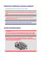
CHAPTER 5 MAINTENANCE REPLACING THE CONSUMABLES You will need to replace the following consumables periodically. When the time comes to replace consumables, the following messages will appear on the LCD panel. The printer will stop printing when the following Operator Call Messages are displayed: LCD Operator Call Message Consumable to Replace Approximate Life How to Replace Order No.
CHAPTER 5 MAINTENANCE The following are Maintenance Messages that appear on the LCD in the READY state. These messages provide advance warnings to replace the consumable items before they run out. To avoid any inconvenience, you may want to purchase spare consumable items before the printer stops printing. LCD Operator Call message Consumable to Replace Approximate Life How to Replace Order No.
CHAPTER 5 MAINTENANCE The following are Maintenance Messages that appear alternatively with the “READY” message on the upper row of the LCD when the printer is in the READY state. These messages advise you that you will need to replace each of the consumables as soon as possible, since the consumable end of life has been reached. The printer will continue printing when any of these messages are displayed: LCD Operator Call Message Consumable to Replace Approximate Life How to Replace Order No.
CHAPTER 5 MAINTENANCE *1 - at 5 % coverage print (A4-Letter size). Note The toner cartridges shipped with the printer are starter cartridges. Each starter cartridge will produce approximately7,000 pages (Black) and 4,250 A4 pages (Cyan, Magenta and Yellow). *2 - For example, if the Cyan and Magenta toner cartridges are almost empty, the indication will be “ ! " " ! ” (" = blinking !) K CM Y If the Cyan and Magenta toner cartridges are empty, the ! indicator will have disappeared.
CHAPTER 5 MAINTENANCE TO ON NE ER R CA AR RTTR RIID DG GE ES S ! Caution We strongly recommend using genuine Brother toner cartridges. Using generic or refilled toner cartridges may void the warranty for this printer. Toner Nearly Empty Message Check printed pages, page counter, and display messages periodically. If the " indicator starts blinking (!), the printer has nearly run out of toner or the toner is not evenly distributed inside the cartridge.
CHAPTER 5 MAINTENANCE Replacing the Toner Cartridges ! Caution When replacing the Toner Cartridges, handle them carefully so that toner does not spill. Note To ensure optimum print quality, use genuine Brother toner cartridges. Third party toner cartridges may not work in your printer. To obtain genuine Brother supplies, consult the dealer where you purchased the printer. To replace the toner cartridge(s), follow these steps: 1. Open the Front Cover of the printer. 2.
CHAPTER 5 MAINTENANCE 4. Insert the new Toner Cartridge(s) by positioning it in the correct guide(s). Slide it gently into the printer. Do not try to lock or push it in; it should rest loosely in the guide rails. Note that each color cartridge is individually keyed to prevent improper installation. Match each cartridge color label to the corresponding label on the printer. Fig. 5-2 5. Close the Front Cover.
CHAPTER 5 MAINTENANCE ! Caution • Insert the toner cartridges gently into the printer. Do not try to lock them into place by pushing them. Toner cartridges should rest loosely in the guide rails; they will be correctly positioned when the front cover is closed. • The printer may be damaged or may not work correctly if you install consumables other than genuine Brother supplies or if you use refilled toner cartridges. This could void your warranty.
CHAPTER 5 MAINTENANCE OIILL BO OTTTTLLE E Oil Bottle Low Message When the Oil has almost run out, the following message appears on the LCD panel. Obtain a new Oil Bottle to replace the nearly empty bottle. After this message appears, you can print approximately 30 pages: FUSER OIL LOW !" READY Oil Bottle Empty Message When the Oil completely runs out, the following message appears on the LCD panel and the printer stops printing.
CHAPTER 5 MAINTENANCE ! Warning The Fusing Unit and the parts around it are HOT! Be sure to wait until the Fusing Unit has cooled sufficiently before replacing the Oil Bottle. If you touch the HOT parts, you might get injured. ! Caution Be careful not to spill oil inside the printer. I may cause considerable damage and void your warranty. If you spill some oil, consult your dealer or Brother authorized service representative.
CHAPTER 5 MAINTENANCE Replacing the Oil Bottle 1. Press the Power button to turn off the printer and wait until it has cooled down sufficiently. 2. Open the Top Cover. 3. Release the Oil Bottle Lock Levers as shown: Fig. 5-4 4. Remove the empty Oil Bottle from the Fusing Unit. Hold a sheet of paper under the Oil Bottle and lift it out of the Fusing Unit. Move the bottle away from the printer to the right so the oil will not spill into it. Be careful not to spill oil inside the printer.
CHAPTER 5 MAINTENANCE 5. Install the new Oil Bottle into the Fusing Unit with the label facing you. The Oil Bottle is keyed to prevent incorrect installation. Fig. 5-6 6. Lock the Oil Bottle Lock Levers securely. 7. Close the Top Cover. 8. Press the Power button to turn the printer On.
CHAPTER 5 MAINTENANCE FUUSSEERR CLLEEAANNEERR Fuser Cleaner Message When the following message appears on the LCD panel, the printer will stop printing and the Fuser Cleaner will need to be replaced: REPLACE FCR !" READY Fuser Cleaner Change Message When the following message appears on the LCD panel and the printer stops printing, you must replace the Fuser Cleaner: CHANGE FCR Replace the cleaning roller 5-13
CHAPTER 5 MAINTENANCE Replacing the Fuser Cleaner ! Warning The Fusing unit and the parts around it are HOT! Be sure to wait until the Fusing Unit has cooled sufficiently before replacing the Fuser Cleaner. If you touch the HOT parts, you might get injured. 1. Press the Power button to turn the printer off and wait until it has cooled down sufficiently. 2. Open the Top Cover. 3. Release the Fuser Cleaner Lock Levers on both sides as shown: Fig.
CHAPTER 5 MAINTENANCE 4. Take the Fuser Cleaner out of the Fusing Unit by holding the handle of the Fuser Cleaner as shown below. Fig. 5-8 5. Install the new Fuser Cleaner into the guide with the roller side facing you. Fig. 5-9 6. Lock the Fuser Cleaner with the Fuser Cleaner Lock Levers. 7. Close the Top Cover. 8. Press the Power button to turn the printer On. 9. Press any of the Menu buttons (+, –, Set or Back) to take the printer Off Line. 10. Press + or – until “RESET MENU” appears. 11.
CHAPTER 5 MAINTENANCE WAASSTTEE TO ON NE ER R PA AC CK K After approximately every 18,000 A4 or letter size images have been printed at 5% coverage, you must change the Waste Toner Pack. NEAR WASTE TONER !" READY Waste Toner Pack Full Message When the Waste Toner Pack is full, the following message appears on the LCD panel and the printer will stop printing.
CHAPTER 5 MAINTENANCE 1. Open the Front Cover. 2. Remove the Waste Toner Pack from the holder located at the lower right side of the printer. Be careful not to spill the toner. Fig. 5-10 3. Peel off the sealing sticker on the right side of the Waste Toner Pack. Seal the opening with the sealing sticker. See Fig. 5-11 for the correct placement of the sticker. When you dispose of the used Waste Toner Pack, place it in the plastic bag included with the replacement Waste Toner Pack.
CHAPTER 5 MAINTENANCE OPC BEELLTT CAARRTTRRIIDDG GE E OPC Belt Cartridge Message When the OPC Belt Cartridge runs out, the following message appears on the LCD panel. When you see this message, you must replace the OPC Belt Cartridge: REPLACE OPC BELT !" READY ! Caution • Do not touch the surface of the OPC Belt Cartridge. If you touch it, it could degrade print quality. • Do not expose the OPC Belt Cartridge to light (more than 800 lux) for more than 2 minutes. This could degrade print quality.
CHAPTER 5 MAINTENANCE Replacing the OPC Belt Cartridge 1. Press the Power button to turn the printer off. 2. Open the Front Cover, and then open the Top Cover. 3. Pull the green Belt Cartridge Lock Levers on both sides toward you to release the lock. Fig. 5-12 4. Remove the OPC Belt Cartridge from the printer. Fig. 5-13 5. Remove the Tension Release Pins from both sides of the new OPC Belt Cartridge. Fig.
CHAPTER 5 MAINTENANCE 6. Remove the protective sheet from the new OPC Belt Cartridge. Do not touch the green part of the OPC Belt Cartridge. Fig. 5-15 7. Insert the new Belt Cartridge into the printer guides with the flat side facing you. Fig. 5-16 8. Press the Belt Cartridge Lock Levers on both sides of the OPC Belt Cartridge to the rear to lock the cartridge into the printer. 9. Close the Front Cover and the Top Cover. 10. Press the Power button to turn the printer On. 11.
CHAPTER 5 MAINTENANCE OZZO ON NE E FIILLTTE ER R Ozone Filter You will need to replace the Ozone Filter once a year to prevent ozone from coming out of the printer. ! Caution You must replace the Ozone Filter once a year. If you do not, it might cause a noticeable smell of Ozone. Replacing the Ozone Filter 1. Slide and remove the Rear Side Cover. Fig. 5-17 2. Remove the Ozone Filter Case from the Rear Side Cover. Fig. 5-18 3. Insert the new Ozone Filter Case into the Rear Side Cover. 4.
CHAPTER 5 MAINTENANCE FUUSSIINNG G UN NIITT Fusing Unit When the following message appears on the LCD panel, you must replace the Fusing Unit: REPLACE FUSER !" READY ! Warning The Fusing Unit and the parts around it are HOT! Be sure to wait until the Fusing Unit has cooled down sufficiently before replacing the Fusing Unit. If you touch the HOT parts, you might get injured. ! Warning After replacing the Fusing Unit, wait for approximately 30 minutes before printing to allow the fusing oil to circulate.
CHAPTER 5 MAINTENANCE Replacing the Fusing Unit 1. Press the Power button to turn off the printer. Unplug the printer. To avoid injury, wait until the printer has cooled down sufficiently before replacing the Fusing Unit. 2. Open the Top Cover. 3. Unscrew the two long screws as shown to release the Fusing unit from the printer. Fig. 5-19 Note Please wait for 30 minutes after installing a new Fusing Unit to allow the oil to circulate completely through to the Heat Roller.
CHAPTER 5 MAINTENANCE ! Caution When removing the Fusing Unit from the printer, be sure to keep the Fusing Unit flat, so oil will not spill. Damage can occur if oil is spilled inside the printer. 5. Remove the Oil Bottle and the Fuser Cleaner from the Fusing Unit. 6. Install the new Fusing Unit into the printer. Be sure to insert the Fusing Unit completely into the printer. Fig. 5-21 7. Secure the Fusing Unit with the two long screws. Fig.
CHAPTER 5 MAINTENANCE 8. Move the Fusing Unit Pressure Release Levers to the SET position. Fig. 5-23 9. Install the Fuser Cleaner and the Oil Bottle into the new Fusing Unit and lock the Oil Bottle Lock Levers and the Fuser Cleaner Lock Levers. Be careful not to spill oil inside the printer. This could damage the printer. Note If the condition of the Fuser Cleaner is poor, we recommend that you replace the Fuser Cleaner at the same time as the Fusing Unit.
CHAPTER 5 MAINTENANCE 16. Press Set, and then press Go. The printer is now in the READY state. ! Caution Please be careful when replacing the Fusing Unit. Do not place pressure on the Fusing Unit; it should fit in easily. If it does not, make sure the Fusing Unit connector is free to move. Do not apply force! It could damage both the Fusing Unit and the printer.
CHAPTER 5 MAINTENANCE 120K KIITT 120K Kit When you see the following message on the LCD panel, you must replace the items supplied in the 120K Kit, which includes the Paper Discharger. Note • User replacement of some of the following 120K Kit parts is not recommended. • We recommend that you contact your local Brother authorized dealer or service center for replacing the Paper Feeding Roller, Separator Pad and Transfer Drum.
CHAPTER 5 MAINTENANCE Paper Discharger ! Caution Do NOT touch the charging wire! Fig. 5-24 Replacing the Paper Discharger 1. Press the Power button to turn the printer Off, and then unplug the printer. 2. Open the Rear Access Cover. 3. Remove the Paper Discharger from the Transfer Unit by lightly pressing it down and then sliding it to the right to release it from the catches. Hold the right hand side of the Discharging Unit and lift it up to remove it. Fig.
CHAPTER 5 MAINTENANCE 4. Install the new Paper Discharger into the Transfer Unit in the reverse order that you removed it. Fig. 5-26 5. Plug the power cord into the power outlet and press the Power button to turn on the printer. Note • User replacement of some of these parts is not recommended. • For replacement of the Paper Feeding Roller, Separator Pad and the Transfer Drum, consult your local dealer/retailer.
CHAPTER 5 MAINTENANCE 240K KIITT 240K Kit When you see the following message on the LCD control panel, you must replace the items located in the 240K Kit, which includes the Drum Cleaner and the Transfer Roller. Note • User replacement of some of the following 240K Kit parts is not recommended. • For user replacement of the Drum Cleaner and Transfer Roller please refer to the instructions below.
CHAPTER 5 MAINTENANCE Replacing the Drum Cleaner ! Caution Both ends of the Drum Cleaner roller consist of metal bearings that connect the bias element to the power supply. When you install the Drum Cleaner, the metal bearings must be connected correctly. Be sure to check how they are connected by referring to the old Drum Cleaner before you begin replacement. 1. Press the Power button to turn the printer Off, and then unplug the printer. 2. Open the Top Cover. 3. Remove the Drum Cleaner Cover. Fig.
CHAPTER 5 MAINTENANCE 5. Install the new Drum Cleaner into the printer by gently placing the brass bearings into the guides, and then pushing the handle down until the bearings click into place. Ensure that the Drum Cleaner is free to move slightly upward (rotating slightly around the bearings) in the housing after you have installed it. Fig. 5-29 6. Re-install the Drum Cover, and then close the Top Cover. 7. Press any of the Menu buttons (+, –, Set or Back) to turn the printer Off line. 8.
CHAPTER 5 MAINTENANCE Replacing the Transfer Roller 1. Release the Transfer Roller Lock Levers by lifting them up. Fig. 5-30 2. Hold the Transfer Roller Lock Levers to lift the used Transfer Roller up and out. Fig.
CHAPTER 5 MAINTENANCE 3. Install the new Transfer Roller by holding the Lock Levers of the Transfer Roller and adjusting the angle of the Transfer Roller Lever shafts (both sides) to match the Transfer Unit groove. Set the Transfer Roller onto the shafts and place the Roller onto the springs as shown below: Fig. 5-32 Lock Levers Transfer Roller Shaft Spring Fig. 5-34 Fig. 5-33 4. Lock the new Transfer Roller into place with the Transfer Roller Lock Levers. 5. Close the Rear Access Cover. 6.
CHAPTER 5 MAINTENANCE 10. Press Set, and then press + until “240K KIT” appears. 11. Press Set, and then press Go. The printer is now in the READY state. Note • User replacement of some of these parts is not recommended. • For replacement of the Paper Feeding Roller, Separator Pad and the Transfer Drum, consult your local dealer/retailer.
CHAPTER 5 MAINTENANCE CLEANING THE PRINTER Clean the printer exterior and interior periodically with a dry soft cloth. If the printed page gets stained with toner, clean the printer interior with a dry soft cloth. CLLEEAANNIINNG RIIN XTTE NTTE ER RIIO ER R EX OR G TTH R HE E PR Clean the printer exterior as follows: 1. Turn off the printer and unplug the power cord. 2. Remove the Media Cassette from the printer. 3. Wipe the printer body with a soft cloth to remove dust.
CHAPTER 5 MAINTENANCE PEERRIIO OD DIIC C PR RIIN NTTE ER R CLLE EA AN NIIN NG G After every 20,000 pages printed or every 12 months, we recommend cleaning the following parts with a dry cloth. Clean the Paper Guide and Registration Roller to prevent paper jams. Fig. 5-36 Clean the Exit Roller after opening the Top Cover slightly. This will help to prevent paper jams at the paper exit or dirt from appearing on your print output. Fig.
CHAPTER 5 MAINTENANCE REPACKING AND RELOCATING THE PRINTER ! Caution, Warning • Whenever you transport the printer ALWAYS use the packing materials that were provided with your printer. Follow the steps detailed below to re-pack the printer or the printer may be damaged. This will void the printer’s warranty.
CHAPTER 5 MAINTENANCE HO OW W TTO O RE EP PA AC CK K TTH HE E PR RIIN NTTE ER R 1. Press the Power button to turn off the printer, and then unplug the printer. 2. Remove the Waste Toner Pack, the Toner Cartridges, the Fusing Unit and the OPC Belt Cartridge from the printer. Place them in their original packaging. Do not pack them together with the printer in the printer carton. 3. Place the printer in its original packing material and in the original carton. 4. Close the carton and tape it securely.
CHPTER 6 OPTIONS CHAPTER 6 OPTIONS
CHAPTER 6 OPTIONS LOWER TRAY UNIT (LT-34CL) LO OA AD DIIN NG G PA APPEER R IIN NTTH HEE LO OW WEER R PA APPEER R CA AS SS SEETTTTEE The lower tray functions as a second paper source. It can hold a maximum of 500 sheets of paper (75 g/m2 or 20 lbs). To purchase the optional lower tray unit, please consult the dealer where you purchased the printer. With the lower tray unit installed, load paper in the lower paper cassette in the same way as you do the upper media cassette.
CHAPTER 6 OPTIONS 1. Remove the Paper Cassette from the printer. 2. Place the Lower Tray Unit on a flat surface. 3. Adjust the Anchor Feet, located at the rear and right hand side at the bottom of the Lower Tray Unit, to level the tray unit. The Anchor Foot moves up and down as it is turned. Adjustment is completed when the Anchor Foot touches the surface of the work surface and the tray unit is level. Turn the lock screw to secure the Anchor Foot. Fig. 6-1 4.
CHAPTER 6 OPTIONS 6. Check the two alignment pins on the Lower Tray Unit. Use two people to lift the printer and place it onto the Lower Tray Unit. Be sure to use the handholds located at the bottom four corners of the printer. Check to ensure that the pins align correctly into the printer. Fig. 6-4 7. Remove the Connection Cable cover. Fig. 6-5 8. Securely connect the printer and the Tray Unit at the rear with the metal lock plate and the screw.
CHAPTER 6 OPTIONS 9. Insert the connection cable into the printer’s connector. Fig. 6-7 10. Lock the printer and the Tray unit at the front by turning the Metal Plate Lock as shown below. Fig. 6-8 11. Install the covers on both sides of the Lower Tray Unit. Install the covers by fitting them first to the rear of the printer and then fit the cover into the front of the printer. Fig.
CHAPTER 6 OPTIONS 12. Install the Paper Cassette into the Lower Tray Unit. 13. Install the Paper Cassette into the printer.
CHAPTER 6 OPTIONS HO OW APPEER AM OW RA NIITT WTTO MS WEER AY AR S IIN Y UN O CLLEEA R PA R JA RTR NTTH HEE LO Paper Jam in the Cassette 1. When a Paper Jam has occurred in the Paper Cassette, remove the Paper Cassette from the printer. Pull the Cassette out half way, slightly lift it, and then pull the cassette from the printer. 2. Remove the jammed paper and reinstall the cassette into the printer. Paper Jam at the Rear of the Lower Tray Unit 1.
CHAPTER 6 OPTIONS DUPLEX UNIT (DX-3400) The following paper sizes can be used for the Duplex Unit. 330 x 483 mm (13 x 19"), A3, A4, B4, B5 Executive, Ledger, Legal, Letter Note • The Lower Tray Unit must be connected before you install the Duplex Unit. • When you perform maintenance on the printer, open the Duplex Top Cover Assembly first. • When you want to open the Rear Access Cover of the printer, open the Duplex Lower Cover and the inside unit. 1.
CHAPTER 6 OPTIONS 4. Remove the Back caps (2 pieces) of the Lower Tray Unit. Push down lightly on the caps and slide them to the rear of the printer to remove them. Fig. 6-12 5. Use the handholds of the Duplex Unit to lift the Duplex Unit up. Fig. 6-13 Note Ensure that the Duplex Cover Top Assembly is aligned and latched straight with the lower part of the duplex unit. 6. Insert the fixing pins at the sides of the Duplex Unit into the installation grooves in the Lower Tray Unit. Fig.
CHAPTER 6 OPTIONS 7. Secure the pawls of the Duplex Unit into the rectangular holes in the back of the printer. Fig. 6-15 8. Open the Duplex Cover Top Assembly. 9. Securely connect the Duplex Unit and the Printer with the thumb screws (2 pieces). Fig. 6-16 10. Close the Duplex Cover Top Assembly.
CHAPTER 6 OPTIONS 11. Connect the connector cable to the upper connector on the printer. Fig. 6-17 12. Fit the left hand side cover of the Lower Tray Unit to the Lower Tray Unit. 13. Plug the power cord into the AC outlet, and then turn the printer on.
CHAPTER 6 OPTIONS COMPACTFLASH CARD / HARD DISK DRIVE (HD-6G/HD-EX) CO OM MPPA AC CTTFLLA AS SH H CA AR RD D This printer has a slot for an optional CompactFlash card, which is a memory card. If you install an optional CompactFlash memory card, you can save macros, print log and fonts on it, and also select the re-print functions via the network.
CHAPTER 6 OPTIONS HAARRDD DIISSKK DRRIIVVEE (HD-6G / HD-EX) If you install an optional HDD, you can save macros, print log and fonts on it, and also select your print job and re-print it through the network. Confirm that the box contains the following items. • • • • • Hard disk Hard disk cables (2) Shoulder screws (4) Screws (4) Setup guide Note The supplied longer cable is for other printers, do not use it for this printer model.
CHAPTER 6 OPTIONS Note When you select the fonts through your software or with a command, note the following: • You do not need to be concerned about the Font control panel setting. The software or command setting overrides the printer setting. • Be sure to install the font card that has your desired fonts. The printer automatically selects the font that has exactly the same or similar characteristics as those you set through the software or with a command.
CHAPTER 6 OPTIONS Font Number Fig. 6-18 6. Use + or – on the Control Panel to select “PRINT MENU.” 7. Press Set to proceed to the next menu level, and then press + or – to select: “HP LASERJET,” “EPSON FX-850”, or “IBM PROPRINTER.” 8. Press the Set key to select the Emulation for the fonts you want to select; “HP LASERJET,” “EPSON FX-850,” or “IBM PROPRINTER.” 9. Use + or – key to select “FONT NO,” and then select the Font Number of the font you want.
CHAPTER 6 OPTIONS IN NS OM AR STTA MPPA AS RD SH D ALLLLIIN AC H CA CTTFLLA NG GA A CO 1. Turn off the printer, and then unplug the power cord from the AC outlet. Disconnect the interface cable from the printer. 2. Insert a CompactFlash card into the slot with the label facing you. Make sure it is inserted correctly. Fig. 6-19 3. To remove the card, power the printer off, and then pull the card out of the slot.
CHAPTER 6 OPTIONS IN NS AR RIIV STTA RD SK D DIIS K DR VEE) ALLLLIIN NG GA A HDD (HA 1. Turn off the printer, and then unplug the power cord from the AC outlet. Disconnect the interface cable from the printer. 2. Unscrew the two screws securing the rear plate of the main controller board, and then pull out the main controller board. Fig. 6-20 3. Insert the 4 shoulder screws supplied with the HD-6G/HD-EX unit into the bottom of the HD6G/HD-EX. Fig. 6-21 4.
CHAPTER 6 OPTIONS 5. Fit the 4 HD-6G/HD-EX shoulder screws into the 4 holes of the main controller board, and then secure the shoulder screws with the screws provided from the rear of the PCB. Fig. 6-23 6. Connect the flat cable to the main controller board. Fig. 6-24 7. Install the main controller board into the printer by sliding it into the guide rails. Fig. 6-25 8. Secure the main controller board with the 2 screws. 9. Reconnect the interface cable to the printer.
CHAPTER 6 OPTIONS RAM EXPANSION This printer has 64 Mbytes of memory standard memory. The memory can be expanded up to 384 Mbytes. When you want to upgrade to more than 320 Mbytes, you will need to remove the already installed 64 Mbytes DIMM and replace it with a higher capacity DIMM. (The standard installed memory can vary depending on the printer model and country.
CHAPTER 6 OPTIONS In general, the DIMM must have the following specifications: Type: 100 pin and 32 bit output CAS Latency: 2 Clock Frequency: 66MHz or more Capacity: 16,32, 64 or 128 Mbyte Height: 46mm (1.8 inches) or less Parity: NONE Dram Type: 64M bit SDRAM 4 Bank SDRAM can be used. Note • There might be some DIMMs that will not work with this printer. • For more information consult the dealer where you purchased the printer. • For the latest information: http://solutions.brother.
CHAPTER 6 OPTIONS 2. Unscrew the two screws that secure the rear plate of the main controller board, and then pull out the main controller board. Fig. 6-26 3. Unpack the DIMM and hold it by its edges. ! Caution Do not touch the memory chips and the surface of the main controller board. If static electricity collects, it may damage these electrical parts. 4. Hold the DIMM with your fingers on the side edges and thumb against the back edge. Align the notches on the DIMM with the DIMM slot.
CHAPTER 6 OPTIONS 5. Press the DIMM straight into the slot (press firmly). Make sure the locks on each side of the DIMM snap inward into place. (To remove a DIMM, the locks must be released.) 6. Reinstall the main controller board into the printer by sliding it into the guide rails. Fig. 6-28 7. Secure the main controller board with the two screws. 8. Reconnect the printer cable from your computer. Plug the power cord into the AC outlet, and turn on the printer. 9.
CHAPTER 7 TOURBLE SHOOTING CHAPTER 7 TROUBLE SHOOTING
CHAPTER 7 TROUBLE SHOOTING TROUBLESHOOTING If any problems occur, the printer automatically stops printing, diagnoses the problem, and then displays the resulting message to alert you. Take the appropriate action, referring to the following tables. If you cannot clear the problem, consult the dealer where you purchased the printer. Inform the dealer of the message number for quick troubleshooting.
CHAPTER 7 TROUBLE SHOOTING Error Message Remarks NO PAPER T1/2/3 Load paper into Tray 1/2/3. WASTE TONER Replace the waste toner pack. OIL EMPTY Replace the oil bottle. CHANGE FCR Replace the cleaning roller. NO OPC BELT Install the OPC belt. NO FC ROLLER Install the cleaning roller. NO LFU When the Duplex Unit is installed. Install the lower tray unit. NO TR ROLLER Install the transfer roller. ILLEGAL TONER Use only Brother genuine toner cartridge.
CHAPTER 7 TROUBLE SHOOTING Error Message Remarks MEDIATYPE ERROR XX = T1, T2, T3 or DX Specify the correct media type: XX XX=T1, T2, T3, or DX NO FUSING UNIT A fusing unit was not detected. Please install one. CARD ERROR An error occurred while accessing the Flash card. Check that the driver is formatted and not in Write Protect mode. HDD ERROR An error occurred while accessing the HDD. Power cycle the printer and check that it is formatted. DIMM ERROR Ensure that the DIMM is installed correctly.
CHAPTER 7 TROUBLE SHOOTING MAAIINNTTEENNAANNCCEE MEESSSSAAG GE ES S Error Message Meaning Action When the ! indicator blinks ("), the indicated color toner is nearly empty. K: Black, C: Cyan, M: Magenta, Y: Yellow. When the toner becomes empty, the ! indicator disappears completely. The Oil in the Oil Bottle is almost empty. It is time to replace the Cleaning Roller. It is time to replace the OPC Belt Cartridge. Be ready to replace the Toner Cartridge(s) when the toner is nearly empty.
CHAPTER 7 TROUBLE SHOOTING CAALLLL SEERRVVIICCEE MEESSSSAAG GE ES S When any of the following messages appear on the LCD, turn off the printer. Wait a few seconds, and then turn the printer on again. If this does not clear the problem, consult your dealer or Brother Authorized Service Representative. Call Service Message Meaning Action ERROR EC3 WARNING ERROR EC4 WARNING ERROR EC7 WARNING ERROR ED1 WARNING ERROR ED2 WARNING NVRAM ERROR Turn off the printer.
CHAPTER 7 TROUBLE SHOOTING Service Call Message Meaning Action ERROR EE4 WARNING ERROR EE5 WARNING ERROR EE6 WARNING ERROR EE7 WARNING ERROR EE8 WARNING ERROR EE9 WARNING ERROR EEL WARNING ERROR EF0 WARNING ERROR EF2 WARNING ERROR EF4 WARNING ERROR EF5 WARNING ERROR EH0 WARNING ERROR EH2 WARNING Toner empty sensor error Turn off the printer. Wait a few seconds, and then turn it on again. Transfer roller solenoid error Turn off the printer. Wait a few seconds, and then turn it on again.
CHAPTER 7 TROUBLE SHOOTING Service Call Message Meaning Action ERROR EH4 WARNING Fuser temperature 4 error Turn off the printer. Wait 15 minutes, and then turn it on again. ERROR EL1 WARNING ERROR EL2 WARNING ERROR ELL WARNING ERROR EP1 WARNING ERROR EP3 WARNING Beam detector error Turn off the printer. Wait a few seconds, and then turn it on again. Scanner motor error Turn off the printer. Wait a few seconds, and then turn it on again. Laser power error Turn off the printer.
CHAPTER 7 TROUBLE SHOOTING PAAPPEERR JAAM MS S This printer has been designed to be trouble free. However, if a problem should occur, note the display message and take the appropriate action. This section describes the actions to be taken to avoid paper jams and unsatisfactory printouts. Paper Jam If paper jams inside the printer, it will stop printing and display the following message. JAM X* Refer to the diagram in the printer and check the location. Remove the jammed paper.
CHAPTER 7 TROUBLE SHOOTING If more than two places appear in the LCD, clear them one at a time by following the steps in ‘How to Clear a Paper Jam in the Printer’. Note Do not use the following paper: • Bent paper • Moist paper • Paper that does not meet specifications Paper may jam in the Paper Cassette, inside the printer, at the Rear Access Cover or at the paper exit. Locate the jam, and then follow the instructions below to remove the jammed paper.
CHAPTER 7 TROUBLE SHOOTING How to Clear a Paper Jam in the Printer PAPER JAM AT PAPER EXIT JAM E1 If paper has passed behind the Rear Access Cover and a paper jam has occurred at the paper exit, follow the steps below: 1. Open the Top Cover, and then release the Fusing unit Pressure Release Levers. Fig. 7-1 2. Open the Rear Access Cover, and then remove the jammed paper by pulling it out slowly. Fig. 7-2 3.
CHAPTER 7 TROUBLE SHOOTING Note If the number of paper jams at the Rear Access Cover increases, replace the Paper Discharger. PAPER JAM AT FUSING ROLLER INSIDE THE PRINTER JAM D Or JAM E2 If a paper jam occurs at the Fusing Roller, follow the same steps to remove the jammed paper as listed for ‘Paper Jam at Paper Exit’. Otherwise, follow the steps below: ! Warning The Fusing Roller is extremely HOT during operation. Remove the paper carefully.
CHAPTER 7 TROUBLE SHOOTING 1. Open the Rear Access Cover. 2. Remove the jammed paper by holding it with both hands and pulling it slowly toward you. Fig. 7-3 3. Close the Rear Access Cover. ! Caution • Do not touch the toner surface of the jammed paper. It might stain your hands or clothes. • If you remove the jammed paper and the next printed page is stained with toner, print several test pages before restarting your print job. • Remove the jammed paper carefully to prevent spreading toner.
CHAPTER 7 TROUBLE SHOOTING PAPER JAM IN THE PAPER CASSETTE JAM A1 Or JAM A2 Or JAM A3 If a paper jam occurs inside the Paper Cassette, follow these steps: 1. Pull out the Paper Cassette. 2. Remove the jammed paper. Fig. 7-4 3. Re-install the Paper Cassette. 4. Open the Rear Access Cover and check that there is no more jammed paper inside. ! Caution Do not remove the upper Paper Cassette while printing from the optional lower Paper Cassette. This will cause a paper jam.
CHAPTER 7 TROUBLE SHOOTING How to Clear a Paper Jam in the Duplex Unit PAPER JAM IN THE DUPLEX COVER TOP ASSEMBLY JAM B If a paper jam occurs in the Duplex Cover Top Assembly, follow these steps: 1. Open the Duplex Cover Top Assembly. 2. If you see a jammed piece of paper through the viewing window, push the paper down and then remove the jammed paper. Fig.
CHAPTER 7 TROUBLE SHOOTING PAPER JAM IN THE LOWER ASSEMBLY OF THE DUPLEX UNIT JAM C If a paper jam occurs in the Lower Assembly, follow these steps: 1. Open the Duplex Lower Cover. If you find a jammed piece of paper, remove it. Fig. 7-6 2. If you cannot find the jammed paper, open the Inside Unit by holding the handles and pulling it toward the rear. If you find a jammed piece of paper, remove it. Fig.
CHAPTER 7 TROUBLE SHOOTING 3. If you cannot still find the jammed paper, open the cover of the Inside Unit and remove the jammed paper. Fig. 7-8 4. Close the Cover of the Inside Unit, the Inside Unit and the Duplex Lower Cover.
CHAPTER 7 TROUBLE SHOOTING PAPER JAM IN THE FUSING UNIT WITH THE DUPLEX UNIT INSTALLED When the following message appears on the LCD with the Duplex Unit installed, follow the steps below to remove the jammed paper. JAM E1 Or JAM E2 1. Open the Duplex Lower Cover. Fig. 7-9 2. Open the Inside Unit of the Duplex Unit. Fig.
CHAPTER 7 TROUBLE SHOOTING 3. Open the Rear Access Cover of the printer. Fig. 7-11 4. Open the Duplex Cover Top Assembly. Fig. 7-12 5. Open the Top Cover of the printer, and then set the Pressure Release Levers of the Fusing Unit to the OPEN position. Fig.
CHAPTER 7 TROUBLE SHOOTING 6. With all the covers and units open, remove the jammed paper. Access and remove the jammed paper from the Rear Access Cover. Fig. 7-14 7. Set the Pressure Release Levers of the Fusing Unit to the SET position, and then close the Top Cover. Fig. 7-15 8. Close the Duplex Cover Top Assembly. 9. Close the Rear Access Cover of the printer. 10. Close the Inside Unit and the Duplex Lower Cover of the Duplex Unit.
CHAPTER 7 TROUBLE SHOOTING Q&A Occasionally you may encounter a difficulty with your HL-3450CN printer. This section contains frequently asked questions and the answers. Find your question below, and then follow the recommended steps. You can correct most problems yourself. SEETTTTIINNG P TTH RIIN AR RD NTTE DW HE WA E PR ER AR G UP R HA RE E Question Recommendation The printer does not come on. Check to verify the following; The printer is securely plugged into the AC outlet.
CHAPTER 7 TROUBLE SHOOTING SEETTTTIINNG G UP P TTH HE E PR RIIN NTTE ER R Question I cannot print from my application software. I cannot print the entire page. Computer indicates a device time-out. Computer indicates Paper Empty. Computer indicates Off Line Computer indicates Power Off Computer indicates an error message other than above.
CHAPTER 7 TROUBLE SHOOTING PAAPPEERR HAANNDDLLIINNG G Question The printer does not load paper. How can I load envelopes? Which paper can I use? How can I clear paper jams? The printer feeds more than one sheet at a time. Paper skews while feeding. Sometimes mis-picking of paper from the paper tray or misfeeding of paper from the paper exit occurs. Recommendation • Check to see if the Alarm LED is on. If so, the Paper Cassette may be out of paper or not properly installed.
CHAPTER 7 TROUBLE SHOOTING PRRIINNTTIINNG G Question The printer prints unexpectedly or it prints incorrect characters. The computer hangs up when the printer starts printing, or an application error occurs. The headers or footers appear when I view my document on the screen but do not show up when I print them. Printing takes too long. Recommendation • Cancel the print job from your computer. Then, turn the printer off and on, or reset the printer and try your print job again.
CHAPTER 7 TROUBLE SHOOTING PRRIINNTT QUUAALLIITTYY Note When the LCD indicates the ‘toner low’ or ‘toner empty’ message, you can resolve a print quality problem by replacing a toner cartridge with a new one. Question White horizontal lines or bands or rubbing ABCDEFGHIJKLMNOPQRSTUVWXYZ. 0123456789. abcdefghijklmnopqrstuvwxyz. ABCDEFGHIJKLMNOPQRSTUVWXYZ. 0123456789. abcdefghijklmnopqrstuvwxyz. ABCDEFGHIJKLMNOPQRSTUVWXYZ. 0123456789. abcdefghijklmnopqrstuvwxyz. ABCDEFGHIJKLMNOPQRSTUVWXYZ. 0123456789.
CHAPTER 7 TROUBLE SHOOTING Question Black vertical streaks or bands ABCDEFGHIJKLMNOPQRSTUVWXYZ. 0123456789. abcdefghijklmnopqrstuvwxyz. ABCDEFGHIJKLMNOPQRSTUVWXYZ. 0123456789. abcdefghijklmnopqrstuvwxyz. ABCDEFGHIJKLMNOPQRSTUVWXYZ. 0123456789. abcdefghijklmnopqrstuvwxyz. ABCDEFGHIJKLMNOPQRSTUVWXYZ. 0123456789. abcdefghijklmnopqrstuvwxyz. ABCDEFGHIJKLMNOPQRSTUVWXYZ. 0123456789. abcdefghijklmnopqrstuvwxyz. ABCDEFGHIJKLMNOPQRSTUVWXYZ. 0123456789. abcdefghijklmnopqrstuvwxyz. ABCDEFGHIJKLMNOPQRSTUVWXYZ.
CHAPTER 7 TROUBLE SHOOTING Question Toner is scattered or Toner stains appear ABCDEFGHIJKLMNOPQRSTUVWXYZ. 0123456789. abcdefghijklmnopqrstuvwxyz. ABCDEFGHIJKLMNOPQRSTUVWXYZ. 0123456789. abcdefghijklmnopqrstuvwxyz. ABCDEFGHIJKLMNOPQRSTUVWXYZ. 0123456789. abcdefghijklmnopqrstuvwxyz. ABCDEFGHIJKLMNOPQRSTUVWXYZ. 0123456789. abcdefghijklmnopqrstuvwxyz. The color of your printouts is not what you expected All one color Dirt on back of paper ABCDEFGHIJKLMNOPQRSTUVWXYZ. 0123456789. abcdefghijklmnopqrstuvwxyz.
CHAPTER 7 TROUBLE SHOOTING Question Uneven density appears periodically in the horizontal direction Recommendation 1) Check that the toner cartridges are installed correctly. 2) Check that the OPC Belt Cartridge is installed correctly. ABCDEFGHIJKLMNOPQRSTUVWXYZ. 0123456789. abcdefghijklmnopqrstuvwxyz. ABCDEFGHIJKLMNOPQRSTUVWXYZ. 0123456789. abcdefghijklmnopqrstuvwxyz. ABCDEFGHIJKLMNOPQRSTUVWXYZ. 0123456789. abcdefghijklmnopqrstuvwxyz. ABCDEFGHIJKLMNOPQRSTUVWXYZ. 0123456789. abcdefghijklmnopqrstuvwxyz.
CHAPTER 7 TROUBLE SHOOTING Question Off set image ABCDEFGHIJKLMNOPQRSTUVWXYZ. 0123456789. abcdefghijklmnopqrstuvwxyz. ABCDEFGHIJKLMNOPQRSTUVWXYZ. 0123456789. abcdefghijklmnopqrstuvwxyz. ABCDEFGHIJKLMNOPQRSTUVWXYZ. 0123456789. abcdefghijklmnopqrstuvwxyz. ABCDEFGHIJKLMNOPQRSTUVWXYZ. 0123456789. abcdefghijklmnopqrstuvwxyz. Recommendation 1) Check that the specified paper is being used. 2) Check that the oil is not empty. 3) Replace the Fuser Cleaning Roller ABCDEFGHIJKLMNOPQRSTUVWXYZ. 0123456789.
APPENDIX APPENDIX
APPENDIX PRINTER SPECIFICATIONS PRRIINNTTIINNG G Print Method Electrophotography by semiconductor laser beam scanning Laser Wavelength: 780 nm Output: 5mW max.
APPENDIX FUUNNCCTTIIO ON NS S CPU Toshiba TMPR4955 (266MHz) Emulation Automatic emulation selection • HP Color Printer (PCL5C ) including HP LaserJet 4+ (PCL 5e) and HP LaserJet 5 (PCL 6) monochrome mode • BR-Script3 (Adobe Postscript®3 compatible) • HP-GL • EPSON FX-850 • IBM Proprinter XL Interface Automatic interface selection among IEEE 1284 Parallel, 10/100BaseTX Ethernet, USB1.
APPENDIX ELLEECCTTRRIICCAALL AANNDD MEECCHHAANNIICCAALL Power Source U.S.A. and Canada: Europe and Australia: AC 120 V, 50/60 Hz AC 220 to 240 V, 50/60 Hz Power Consumption Printing (Average): 600 W or less Stand-by: 200W or less Stand-by in sleep mode: 30 W or less Noise Printing: 55 dB A or less Stand-by: 48 dB A or less Temperature Operating: 10 to 32.5°C (50°F to 90.
APPENDIX PAPER SPECIFICATIONS Paper Input Media Trays: • Standard upper tray (Tray 1) • Optional lower tray (Tray 2, Tray 3) • Paper sizes: Standard: Letter, Ledger, Legal, A4, A3, ISO B5, JIS B5, B4, Executive, 330x483mm(13"x19"), and COM10, DL with the Envelope Adapter installed Optional lower tray: Letter, Ledger, A4, A3, B4, Legal, B5 (JIS / ISO) Optional A4/Letter Cassette: Letter, A4, ISO B5, JIS B5, Executive, and COM10, DL with the Envelope Adapter installed • Max.
APPENDIX Optional A4/Letter tray (Tray 1): • Plain paper of Letter, A4, ISO B5, JIS B5, and Executive sizes 176 x 210 mm to 297 x 297 mm (6.9 x 8.2” to 11.7 x 11.
APPENDIX PAAPPEERR The printer is designed to work well with most types of xerographic and bond paper. However, some paper variables may have an effect on print quality or handling reliability. Always test samples of paper before purchasing large quantities to ensure that it provides the desired performance. Some important guidelines when selecting paper are: 1. The Supplier should be informed that the paper or envelopes will be used in a laser printer. 2.
APPENDIX ENNVVEELLO OP PE ES S Most envelopes will perform acceptably on your printer. However, some envelopes will have feeding and print quality problems because of their construction. A suitable envelope should have edges with straight, well creased folds and should not have more than two thickness of paper along the leading edge. The envelope should lie flat and not be of baggy or flimsy construction.
APPENDIX LAABBEELLSS AANNDD OVVEERRHHEEAADDTRRAANNSSPPAARREENNCCIIEESS The printer will print on most types of labels and transparencies designed for use with a laser printer. Labels should have an adhesive that is acrylicbased since such material is more stable at the high temperatures of the fusing unit. Adhesives should not touch any part of the printer because the label stock may stick to the drum or rollers, which would cause jams and print quality problems.
APPENDIX SYMBOL/CHARACTER SETS You can select the symbol and character sets in the HP LaserJet, EPSON FX-850, IBM Proprinter XL emulation modes, and the standard or alternate character set in the HP-GL emulation mode with the PRINT MENU by using the Control Panel. See “PRINT MENU” in Chapter 4.
APPENDIX HP PCL MO OD DE E Roman 8 (8U) ISO Latin1 (0N) ISO Latin2 (2N) ISO Latin5 (5N) PC-8 (10U) PC-8 D/N (11U) PC-850 (12U) PC-852 (17U) PC-8 Turkish (9T) Windows Latin1 (19U) Windows Latin2 (9E) Windows Latin5 (5T) Legal (1U) Ventura Math (6M) Ventura Intl (13J) Ventura US (14J) PS Math (5M) PS Text (10J) Math-8 (8M) Pi Font (15U) MS Publishing (6J) Windows 3.
APPENDIX ISO 2 IRV ISO 4 UK ISO 6 ASCII ISO10 SWE/FIN ISO11 Swedish ISO14 JISASCII ISO15 Italian ISO16 POR ISO17 Spanish ISO21 German ISO25 French ISO57 Chinese ISO60 NOR v1 ISO61 NOR v2 ISO69 French ISO84 POR ISO85 Spanish HP German HP Spanish A-11
APPENDIX EPSON MO OD DE E US ASCII German UK ASCII I French I Danish I Italy Spanish Swedish Japanese Norwegian Danish II UK ASCII II French II Dutch South African PC-8 PC-8 D/N PC-850 PC-852 PC-860 PC-863 PC-865 PC-8 Turkish A-12
APPENDIX IBM MO OD DE E PC-8 PC-8 D/N PC-850 PC-852 PC-860 PC-863 PC-865 PC-8 Turkish A-13
APPENDIX HP-GL MO OD DE E ANSI ASCII 9825 CHR. SET FRENCH/GERMAN SCANDINAVIAN SPANISH/LATIN JIS ASCII ROMAN8 EXT. ISO IRV ISO SWEDISH ISO SWEDISH:N ISO NORWAY 1 ISO GERMAN ISO FRENCH ISO U.K.
APPENDIX SYYM MB BO OLL SE ETTS S SU UP PP PO OR RTTE ED DB BY Y TTH HE E PR RIIN NTTE ER R’S S INNTTEELLLLIIFFO ON NTT CO OM MP PA ATTIIB BLLE E TY YP PE EFFA AC CE ES S PCL Symbol Set Set ID 8U 0N 2N 5N 6N 10U 11U 12U 17U 26U 9T 19U 9E 5T 7J 9J 10J 13J 14J 6J 8M 5M 6M 15U 1U 1E 0U 2U 0S 0I 1S 2S 3S 4S 5S 6S 0G 1G 0D 1D 0F 1F 0K 2K 9U 12J 19M 19L 579L Typeface Alaska Antique Brougham Cleveland Connect-Guatemala Letter Symbol Set Oakland Cond.
APPENDIX PCL Symbol Set Set ID 8U 0N 2N 5N 6N 10U 11U 12U 17U 26U 9T 19U 9E 5T 7J 9J 10J 13J 14J 6J 8M 5M 6M 15U 1U 1E 0U 2U 0S 0I 1S 2S 3S 4S 5S 6S 0G 1G 0D 1D 0F 1F 0K 2K 9U 12J 19M 19L 579L Typeface(Continued) LetterGothic Mary- Oklahoma PC PC Utah Symbol Set 16.
APPENDIX SYYM MB BO OLL SE ETTS S SU UP PP PO OR RTTE ED DB BY Y TTH HE E PR RIIN NTTE ER R’S S TRRUUEETYYPPEE™ AANNDDTYYPPEE 1 FO ON NTT CO OM MP PA ATTIIB BLLE E, A AN ND D ORRIIG YP PE GIIN EFFA NA AC ALL TY CE ES S PCL Symbol Set Set ID 8U 0N 2N 5N 6N 10U 11U 12U 17U 26U 9T 19U 9E 5T 7J 9J 10J 13J 14J 6J 8M 5M 6M 15U 1U 1E 0U 2U 0S 0I 1S 2S 3S 4S 5S 6S 0G 1G 0D 1D 0F 1F 0K 2K 9U 12J 19M 19L 579L Typeface Atlanta BR Copen- Calgary Helsinki Portugal Tennes- W Symbol Set Symbol hagen see Dingbats Roman-8
APPENDIX PCL Symbol Set Set ID 8U 0N 2N 5N 6N 10U 11U 12U 17U 26U 9T 19U 9E 5T 7J 9J 10J 13J 14J 6J 8M 5M 6M 15U 1U 1E 0U 2U 0S 0I 1S 2S 3S 4S 5S 6S 0G 1G 0D 1D 0F 1F 0K 2K 9U 12J 19M 19L 579L Typeface Bermuda Script Symbol Set Roman-8 ISO 8859-1 Latin1 ISO 8859-2 Latin2 ISO 8859-9 Latin5 ISO 8859-10 Latin6 PC-8 PC-8 D/N PC-850 PC-852 PC-775 PC-Turk Windows 3.1 Latin1 Windows 3.1 Latin2 Windows 3.
INDEX INDEX 1 120K Kit G 5-27 Go switch 2 240K Kit H 5-30 High Resolution Control HP LaserJet mode HP-GL mode A accessory Analysis Tool Software Apple LaserWriter automatic emulation selection automatic interface selection 2-8 2-15 2-18 1-8, 3-1 1-7, 3-3 IBM Proprinter XL mode information mode interface interface mode IP address 4-2, 4-14 5-19 2-15 4-30 4-36 Job Cancel switch LCD LCD message LED Legal Cassette Lower Media Cassette Lower Tray Unit 4-1, 4-16 4-17 4-15 1-12 6-1 1-12, 6-1 M D M
INDEX P panel setting paper Paper Discharger Paper Jam paper mode Paper Size parallel interface PCL5C mode PCL6 Power Save Mode PPD print menu print menu mode print quality printer driver printer status message proof data protective sheet public data 4-21 4-39 5-28 7-8 4-23 3-5 3-3 3-1 2-1 1-9 2-18, 2-19 4-40 4-26 2-4 2-1, 2-2, 2-10 4-18 4-8 5-20 4-9 reprint Reprint switch reset menu mode S secure data serial interface Service Call Messages Set switch setup setup mode Standard Media Cassette Storage Man