
Service manual


3-48
Confidential
(4) Release the registration front/rear sensor PCB harness and the LVPS harness from the
securing fixtures.
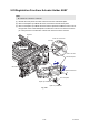
(5) Remove the taptite cup S M3x6 SR screw and the two taptite bind B M4x12 screws, and
remove the main frame R ASSY. Pull out the registration front/rear sensor PCB harness
from the hole.
Fig. 3-51
Harness routing: Refer to “1. Right side of the machine” and “2. Top side of the registration chute”.
Assembling Note:
• When attaching the main frame R ASSY, check that the LVPS FG plate is set to the
main frame R ASSY.
Taptite cup S M3x6 SR
<Overhead view
of frame R>
LVPS FG plate
Hole
Registration front/rear sensor PCB harness
Main frame R ASSY
Taptite bind B M4x12
Hole
Taptite bind B M4x12
<Back side>
LVPS harness
<Bottom side>