
Command Reference Guide for Software Developers
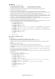
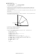

Table Of Contents
- Technical Reference Guide
- TABLE OF CONTENTS
- GLOSSARY
- CHAPTER 1 INTRODUCTION
- CHAPTER 2 PCL PRINTER CONTROL LANGUAGE
- 1. COMMAND LIST
- 2. INTRODUCTION
- 3. CONTROLLING THE PRINTER
- 4. JOB CONTROL
- 4.1 . Commands
- 4.1.1. Page size
- 4.1.2. Media type selection
- 4.1.3. Output tray
- 4.1.4. Paper source
- 4.1.5. Left long-edge offset registration
- 4.1.6. Top offset registration
- 4.1.7. Simplex/duplex printing
- 4.1.8. Paper side selection
- 4.1.9. Job separation command
- 4.1.10. Reset
- 4.1.11. Reset to factory default settings
- 4.1.12. Reset to user settings
- 4.1.13. Printer self test
- 4.1.14. Exit current emulation mode
- 4.1.15. Change emulation mode
- 4.2. The Page
- 4.2.1. Physical page
- 4.2.2. Printable area
- 4.2.3. Logical page
- 4.2.4. Text area
- 4.2.5. HP-GL/2 graphics window
- 4.2.6. Portrait page dimensions
- 4.2.7. Landscape page dimensions
- 4.2.8. Coordinates
- 4.2.9. Units
- 4.2.10. Unit of measure
- 4.2.11. Setting the left and right margins
- 4.2.12. Resetting the horizontal margins
- 4.2.13. Setting the top margin
- 4.2.14. Setting the vertical motion index (VMI)
- 4.2.15. Setting the horizontal motion index (HMI)
- 4.2.16. Setting line spacing
- 4.2.17. Text length
- 4.2.18. Page length
- 4.2.19. Perforation skip
- 4.2.20. Positioning the cursor
- 4.2.21. Vertical positioning
- 4.2.22. Horizontal position
- 4.2.23. Positioning the cursor using control codes
- 4.2.24. Using the cursor position stack
- 4.2.25. Half line feed
- 4.2.26. Logical page orientation
- 4.2.27. Text direction
- 4.1 . Commands
- 5. USING FONTS
- 5.1. Introduction
- 5.1.1. Font types
- 5.1.2. Bitmap fonts
- 5.1.3. Scalable fonts
- 5.1.4. Bound fonts
- 5.1.5. Unbound fonts
- 5.1.6. Font sources
- 5.1.7. Internal fonts
- 5.1.8. Card/cartridge fonts
- 5.1.9. Downloadable fonts
- 5.1.10. Primary and secondary fonts
- 5.1.11. Specifying the primary font
- 5.1.12. Specifying the secondary font
- 5.1.13. Selecting the default fonts
- 5.1.14. Switching between the primary and secondary fonts
- 5.1.15. Criteria for font selection
- 5.1.16. Symbol set
- 5.1.17. Symbol collections
- 5.1.18. Type of character spacing
- 5.1.19. Pitch
- 5.1.20. Height
- 5.1.21. Style
- 5.1.22. Stroke weight
- 5.1.23. Typeface
- 5.2. Font Selection Commands
- 5.2.1. User-defined symbol sets
- 5.2.2. Symbol set ID code command
- 5.2.3. Define symbol set
- 5.2.4. Symbol set control command
- 5.2.5. Selecting the symbol set
- 5.2.6. Selecting the type of character spacing
- 5.2.7. Selecting the pitch
- 5.2.8. Selecting the height
- 5.2.9. Scaling the scalable fonts vertically or horizontally
- 5.2.10. Selecting the style
- 5.2.11. Selecting the stroke weight
- 5.2.12. Selecting the typeface
- 5.2.13. Font orientation
- 5.2.14. Transparent print data
- 5.2.15. Esc&d#D (27)(38)(100)#(68) <1Bh><26h><64h>#<44h>
- 5.3. Downloadable font manipulation
- 5.4. Creating Downloadable Fonts
- 5.1. Introduction
- 6. USING GRAPHICS
- 6.1. Source, Pattern and Destination
- 6.2. Plotting Rectangles
- 6.3. Raster Graphics
- 6.3.1. Positioning the cursor
- 6.3.2. Set raster resolution
- 6.3.3. Set high resolution control
- 6.3.4. Set raster image orientation
- 6.3.5. Set raster area height
- 6.3.6. Set raster area width
- 6.3.7. Set raster y-offset
- 6.3.8. Set compression mode
- 6.3.9. Start raster transfer
- 6.3.10. Send raster data
- 6.3.11. Compress transfer graphics
- 6.3.12. End raster transfer
- 6.3.13. Horizontal 1200-dpi image format mode (Raster Graphic Mode 1027)
- 6.4. Vector Graphics
- 6.5. The Picture Frame
- 7. MACROS
- 7.1. The Purpose of a Macro
- 7.2. Defining a Macro
- 7.3. Running a Macro
- 7.4. Handling Macros
- 7.4.1. Delete all macros
- 7.4.2. Delete all temporary macros
- 7.4.3. Delete macro
- 7.4.4. Make macro temporary
- 7.4.5. Make macro permanent
- 7.4.6. Delete all macros from the storage device
- 7.4.7. Delete macro from the storage device
- 7.4.8. Save macro into the storage device
- 7.4.9. Execute data
- 7.4.10. AppleTalk configuration
- 7.4.11. MIO video I/O port control
- 8. STATUS READBACK
- 8.1. Introduction
- 8.2. Memory Status request
- 8.3. Entity Status
- 8.4. Status Response
- 8.5. Status Response Syntax
- 8.5.1. Set status readback location type
- 8.5.2. Set status readback location unit
- 8.5.3. Inquire status readback entity
- 8.5.4. Entity status response
- 8.5.5. Font response
- 8.5.6. Bitmap fonts
- 8.5.7. Bound scalable fonts
- 8.5.8. Unbound scalable fonts
- 8.5.9. Download fonts
- 8.5.10. Location type 1 (currently selected) font
- 8.5.11. Font extended response
- 8.5.12. Macro response
- 8.5.13. Use-defined pattern response
- 8.5.14. Symbol set response
- 8.5.15. Entity error codes
- 8.5.16. Free space command
- 8.5.17. Font cache
- 8.5.18. Memory status response
- 8.5.19. Memory error response
- 8.5.20. Flush all pages command
- 8.5.21. Echo command
- 9. INDEX
- CHAPTER 3 PCL5C
- CHAPTER 4 HP-GL/2 GRAPHICS LANGUAGE
- CHAPTER 5 PJL PRINTER JOB LANGUAGE
- 1. INTRODUCTION
- 2. HOW TO USE PJL
- 3. COMMAND GROUP
- 4. KERNEL COMMANDS
- 5. JOB SEPARATION COMMANDS
- 6. ENVIRONMENT COMMANDS
- 7. STATUS READBACK COMMANDS
- 8. DEVICE ATTENDANCE COMMANDS
- 9. INDEX
- CHAPTER 6 EPSON FX-850
- CHAPTER 7 IBM PROPRINTER XL
- CHAPTER 8 BAR CODE CONTROL
- 1. INTRODUCTION
- 2. PRINT BAR CODES OR EXPANDED CHARACTERS
- 3. DEFINITION OF PARAMETERS
- 3.1. Bar Code Mode
- 3.2. Bar Code Style, Expanded Character Shading, Line Block Drawing & Box Drawing Shading
- 3.3. Bar Code Scaling (Width only)
- 3.4. Bar Code Human Readable Line On or Off
- 3.5. Quiet Zone
- 3.6. Bar Code, Expanded Character Unit, Line Block Drawing & Box Drawing Units
- 3.7. Bar Code, Expanded Character, Line, Block Drawing & Box Drawing Offset in the X-axis
- 3.8. Bar Code & Expanded Character Offset in the Y-axis
- 3.9. Bar Code, Expanded Character, Line, Block Drawing & Box Drawing Height
- 3.10. Expanded Character, Line Block Drawing & Box Drawing Width
- 3.11. Expanded Character Rotation
- 3.12. Bar Code Data Start
- 3.13. Box Drawing
- 3.14. Line Block Drawing
- 3.15. Expanded Character Data Start
- 3.16. Table of Code(EAN) 128 set C
- 4. EXAMPLE PROGRAM LISTINGS
- CHAPTER 9 HP-GL GRAPHICS LANGUAGE
- CHAPTER 10 CARBON COPY FUNCTION
- APPENDIX A COMPARISON LIST
- APPENDIX B FLASH/PCMCIA CARD COMMANDS
- APPENDIX C HBP MODE COMMANDS
- APPENDIX D REFERENCE LIST OF MX-2000/4000/5000/7000 SERIES UNIQUE COMMANDS
- APPENDIX E REFERENCE LIST OF FS-5050 UNIQUE COMMANDS
- APPENDIX F REFERENCE LIST OF SF- 4000 SERIES UNIQUE COMMANDS

CHAPTER 4 HP-GL/2 - 23
The following flags are used:
':' - Select pen. The number which follows is the required pen number. A PE command that does not
include a select pen command uses the currently selected pen.
'<' - Pen up. The pen is raised and moved to the specified coordinate pair. All coordinate pair values
not preceded by this flag are automatically interpreted as pen down plotting commands.
'>' - Fractional data. The value following the flag specifies the number of fractional binary bits in the
coordinate data.
'=' - Absolute plotting mode. The pair of coordinates which follow this flag are absolute coordinates.
'7' - 7 bit mode. All subsequent coordinate values within this PE command are to be interpreted as 7-bit
values, that is, encoded in base 32.
If you use the ':' flag in polygon mode it is ignored as the SP command has no effect in this mode.
Values and coordinates are encoded in base 64 or base 32. Values determine the setting of the immediately
preceding flag. Legal values and coordinates are as follows:
Pen number - 0 (white) or 1(black)
Number of fractional binary bits - -26 to 26. The default is 0.
x- and y-coordinates - (-2
30
) to 2
30
- 1 current units. If the pen position is moved
outside this range, subsequent plotting commands are ignored until
an absolute coordinate pair within the allowable range is specified.
Flag and coordinate values are encoded as either base 64 or base 32 numbers and then transmitted as ASCII
character codes. Base 64 is the default. Use Base 64 if your computer can send data without a parity bit.
Use base 32 if your system requires a parity bit.
To encode an integer proceed as follows. If the number is negative, take the absolute value, multiply by
2 and add 1. Hence -x : = 2x+1. If the number is positive simply multiply by 2. Hence x :=2x.
Convert the new number into base 64 or base 32 according to your system and encode each base 64 or base
32 digit as the corresponding ASCII character.
To encode a real number proceed as follows. Multiply the number of decimal places in your coordinate's
data by 3.33 and round the result up to the next highest integer (for example round 6.66 up to 7). This
gives the number of binary bits needed to represent the number's fractional part - the value that you will
supply with the '>' flag. Call this number n. Now multiply the number you are encoding by 2
n
. Round
this number to the nearest integer and then follow the procedure described above for encoding an integer.
Transmit each number to the printer least significant digits first. Terminate each number with the most
significant digit. This must be specified from a different ASCII range from the preceding digits in the
number. In base 64, non-terminating digits are represented by the numbers 63-126 and terminating digits
by the numbers 191-254. In base 32, non-terminating digits are represented by the numbers 63-94 and
terminating digits by the numbers 95-126. Hence if using a base 32 number whose least significant digit is
14, and whose most significant digit is 5, encode 14 as 77 (63+14) and 5 as 100 (95+5).
Non-terminator Terminator
Base 64 63-126 191-254
Base 32 63-94 95-126
In symbol mode the PE command draws the specified symbol at each specified point.
In polygon mode the points specified within the PE command are not plotted. Instead they are stored in the
polygon buffer and used when a FP (Fill Polygon) or EP (Edge Polygon) command is used.
The PE command with no parameters simply updates the carriage return point.
CI - Circle plot
CI r(, qd)[;]
r ; Radius of circle ( in current units )
qd ; Chord angle ( in degrees )
The command plots a circle with the current position as the centre, with a radius r and chord angle qd.
After plotting, the cursor returns to the centre of the circle.
Plotting takes place irrespective of whether the pen is up or down.
Valid values for r are specified in the current unit.
Valid values for qd are clamped real numbers in the range 0.5º to 180º. The default value is 5º.