KE-430B, 431B KE-432B, 433B INSTRUCTION MANUAL Please read this manual before using the machine. Please keep this manual within easy reach for quick reference.
Thank you very much for buying a BROTHER sewing machine. Before using your new machine, please read the safety instructions below and the explanations given in the instruction manual. With industrial sewing machines, it is normal to carry out work while positioned directly in front of moving parts such as the needle and thread take-up lever, and consequently there is always a danger of injury that can be caused by these parts.
2. Notes on safety DANGER Wait at least 5 minutes after turning off the power switch and disconnecting the power cord from the wall outlet before opening the face plate of the control box. Touching areas where high voltages are present can result in severe injury. CAUTION Environmental requirements Use the sewing machine in an area which is free from sources of strong electrical noise such as highfrequency welders. Sources of strong electrical noise may cause problems with correct operation.
CAUTION Sewing This sewing machine should only be used by operators who have received the necessary training in safe use beforehand. If using a work table which has casters, the casters should be secured in such a way so that they cannot move. The sewing machine should not be used for any applications other than sewing. Attach all safety devices before using the sewing machine. If the machine is used without these devices attached, injury may result.
3. Warning labels The following warning labels appear on the sewing machine. Please follow the instructions on the labels at all times when using the machine. If the labels have been removed or are difficult to read, please contact your nearest Brother dealer. 1 2 Hazardous voltage will cause injury. Hochspannung verletzungsgefahr! Turn off main switch and wait 5 minutes before opening this cover.
CONTENTS 1. NAME OF EACH PART ............................... 1 9-5. 9-6. 2. SPECIFICATIONS ......................................... 2 2-1. 2-2. Specifications ......................................... Program list ........................................... 2 3 3. INSTALLATION ............................................. 7 3-1. 3-2. 3-3. 3-4. 3-5. 3-6. 3-7. 3-8. 3-9. 3-10. 3-11. 3-12. 3-13. 3-14. 3-15. 3-16. Power table ............................................ Installing the control box ....
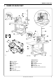
1. NAME OF EACH PART 1.
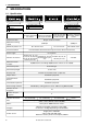
2. SPECIFICATIONS 2. SPECIFICATIONS 2-1. Specifications BROTHER INDUSTRIES, LTD. MADE IN JAPAN 1 5 2 7 Ordinary materials BROTHER INDUSTRIES, LTD. BROTHER INDUSTRIES, LTD. BROTHER INDUSTRIES, LTD.
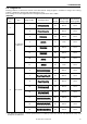
2. SPECIFICATIONS 2-2. Program list Sewing patterns are limited as shown in the table below. (Any program is available as long as the sewing pattern is within the work clamp and feed plate in size.) The sewing size is the length when the enlargement/reduction ratio is 100%. [KE-430B] Specification Use Program No. Sewing pattern No.
2. SPECIFICATIONS Specification -7 Use Program No. Sewing pattern No. of Standard bar stitches tacking length Standard bar tacking width 7 28 8mm 2mm 9 21 7mm 2mm 22 14 7mm 2mm 31 28 8mm 2mm 32 22 8mm 2mm 33 15 8mm 2mm For knitted materials * To prevent thread breakage due to heat, set the sewing speed to a maximum of 2,500 rpm for sewing knitted materials. * The sewing start and sewing end of the sewing patterns for program numbers 31 to 33 are in the middle of the pattern.
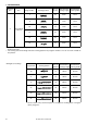
2. SPECIFICATIONS Program No. Sewing pattern No. of Standard bar Standard bar stitches tacking length tacking width 26 28 3mm 10mm 27 35 3mm 10mm 28 19 0.3mm 10mm 29 21 0.3mm 10mm 30 28 0.3mm 10mm Vertical bar tacking vertical straight bar tacking * Use the work clamp and feed plate for straight bar tacking when using the above programs. No.
2. SPECIFICATIONS [KE-431B] Program No. Sewing pattern No. of Standard bar Standard bar stitches tacking length tacking width 1 21 10mm 0.3mm 2 28 10mm 0.3mm 3 28 20mm 0.3mm 4 35 25mm 0.3mm 5 42 25mm 0.3mm 6 45 25mm 0.3mm [KE-432B] Program No. Sewing pattern No. of Standard bar Standard bar stitches tacking length tacking width 1 21 6mm 2mm 2 28 6mm 2mm 3 35 6mm 2mm [KE-433B] This model has no standard patterns.
3. INSTALLATION 3. INSTALLATION CAUTION Machine installation should only be carried out by a qualified technician. All cords should be secured at least 25 mm away from any moving parts. Furthermore, do not excessively bend the cable or secure it too firmly staples, otherwise there is the danger that fire or electric shocks could occur. Contact your Brother dealer or a qualified electrician for any electrical work that may need to be done. The sewing machine head weighs more than 52 kg.
3.
3. INSTALLATION 3-2. Installing the control box Check that the IM sticker is attached to the side of the control box (in the position shown in the illustration). KE series machine heads can only be used with control boxes which have the IM sticker attached.) KE-430B KE-432B KE-433B !0 Table r t Cushions y Cushion collars t y 3mm i Flat washers u i o !1 u Rubber collers o Nuts 0051Q !2 w e 0063Q q r [KE-431B] !0 !2 !1 t y u i o w 0052Q e q 1.
3. INSTALLATION 3-3. Installing the rubber cushions Install the rubber cushions q with the nails w. w q 0053Q 3-4. Installing the oil pan 0054Q q w 1. Insert the tabs of the oil pan w into the holes for the cushions q, and then secure it in place with the five nails e so that the oil pan w is not at an angle. 2. While pushing the oil pan w down from above, screw in the oil container r. e r 0055Q 3-5.
3. INSTALLATION 3-6. Installing the switching plate Install the switching plate q to the work table with the two wood screws w in the position shown in the illustration. * The switching plate and the switch bracket which is attached to the machine head prevent the sewing machine from starting when the machine head is tilted back. Therefore, this means that the sewing machine will not start if the switching plate is not installed. w q 0471Q 3-7.
3. INSTALLATION 3-8. Installing the head rest Tap the head rest q into the table hole. q NOTE: Tap the head rest securely into the table hole. 0060Q 3-9. Installing the liquid cooling tank, optional w 1. Remove the rubber plug, and then push the liquid cooling tank q. 2. Tighten it with the set screw w.
3. INSTALLATION 3-10.Installing the operation panel The operation panel can be installed to either the top or bottom of the work table. 0418Q Top of work table Bottom of work table q r r q e w e t Table w Table t Rubber sheet 2 - 2.5mm 0062Q 0419Q 1. Install the rear frame q to the work table (top or bottom) with the four wood screws w. * At this time, tighten the wood screws w until the thickness of the rubber sheet is 2 to 2.5mm. 2.
3. INSTALLATION 3-12.Connecting the cords 0065Q 0066Q 0068Q t u !0 w o !1 q y i !4 q !2 !3 P8 P1-B A P1-A B P2 G C P3 H D Lock the cord clamp at the top.
3. INSTALLATION 1. Gently tilt back the machine head. NOTE: After tilting back the machine head, do not push the face side or the pulley side from above. 2. Pass the cord bundle q from the machine head through the hole w in the work table. 3. Gently return the machine head to its original position. 4. Remove the six screws e, and then open the control box cover (main P.C. board mounting plate r). NOTE: When opening the cover, hold it securely so that it does not fall down. 5.
3. INSTALLATION 3-13.Installing the belt cover 1. Loosen the two screws w of the upper cover q. 2. Insert the belt cover e in the direction of the arrow, and then secure it with the two screws w and the two screws r. * It is not necessary to remove the belt cover e when tilting back the machine head. w q e r 0069Q 3-14.Installing the foot switch [A] u i y q w !2 e t 0071Q r !1 !0 o e !3 !4 !6 !5 [B] !7 0070Q !8 !9 0072Q 1.
3. INSTALLATION 3-15.Installing the spool stand Assemble the spool stand q while referring to the spool stand instruction manual, and then install the spool stand q at the right side of the work table. q 0073Q 3-16.Installing the eye guard CAUTION Attach all safety devices before using the sewing machine. If the machine is used without these devices attached, injury may result. 0074Q KE-430B KE-432B KE-433B q Install the eye guard assy w to the face plate q with the two screws e.
4. LUBRICATION 4. LUBRICATION CAUTION Turn off the power switch before starting lubricating, otherwise the machine may operate if the foot switch is depressed by mistake, which could result in injury. Be sure to wear protective goggles and gloves when handling the lubricating oil and grease, so that they do not get into your eyes or onto your skin, otherwise inflammation can result. Furthermore, do not drink the oil or eat the grease under any circumstances, as they can cause vomiting and diarrhoea.
5. OPERATION 5. OPERATION 5-1. Name and function of each operation panel item u q P POWER w RESET i TEST t BOBBIN.WIND P1 P2 P3 P4 X-SCALE o Y-SCALE !0 r e PROGRAM NO. SPEED !4 !1 COUNTER SELECT y 0566Q q POWER indicator .................. Illuminates when the power switch has been turned on. w RESET switch ........................ Press this switch to reset the machine when an error occurs. e TEST switch ..........................
5 . OPERATION P POWER RESET i BOBBIN.WIND P1 P2 !3 X-SCALE o Y-SCALE !0 TEST PROGRAM NO. P3 P4 SPEED !4 !1 COUNTER SELECT !2 y 0579Q i X-SCALE indicator ................ Illuminates when the SELECT switch y is pressed to shown the X-scale setting. o Y-SCALE indicator ................ Illuminates when the SELECT switch y is pressed to shown the Y-scale setting. !0 SPEED indicator ................... Illuminates when the SELECT switch y is pressed to shown the speed setting.
5. OPERATION 5-2. Operating procedure Preparation Turn on the power switch. (The POWER indicator q will illuminate and the program number will flash in the display window !4.) Factory default Variable range KE-430B KE-431B KE-432B KE-433B 1 – 35 1–6 1–3 100 – *2 Program No. 0 *1 X-scale (%) 100 20 – 200 Y-scale (%) 100 20 – 200 Speed (rpm) 2,000 1,000 – 2,700 1,000 – 2,500 *1 For checking the origin points for X and Y feed *2 Custom-made program 5-2-1.
6. CHECKING THE SEWING PATTERN 6. CHECKING THE SEWING PATTERN ■ When checking by operating only the feed mechanism 1. Turn on the power switch. (The POWER indicator will illuminate and the program number will flash in the display window.) 2. Press the TEST switch. (The TEST indicator will illuminate.) TEST 0090Q 3. Depress the foot switch to the second step. * For two-pedal foot switch, lower the work clamp before depressing the start switch (right side.
7. CORRECT USE 7. CORRECT USE 7-1. Selecting the needle and thread Different needles and threads are used for different sewing applications. Refer to the table at right for details on which needle and thread to select. Needle Thread Main application DP × 5 #9 #100 - #60 Knitted materials DP × 5 #14 #80 - #50 Ordinary materials DP × 17NY #19 #50 - #20 Denim 7-2.
7. CORRECT USE 7-4. Winding the lower thread CAUTION Do not touch any of the moving parts or press any objects against the machine while winding the lower thread, as this may result in personal injury or damage to the machine. 1. Place the bobbin all the way onto the shaft. 2. Thread the thread as shown in the illustration at right, wind the thread around the bobbin several times in the direction of the arrow, and then press the bobbin presser q. q 3. Turn on the power switch.
7. CORRECT USE 7-5. Replacing the bobbin case and threading the thread CAUTION Turn off the power switch before removing and replacing the bobbin case, otherwise the machine may operate if the foot switch is depressed by mistake and serious injury could result. r w 30mm e q 0110Q 0109Q 0111Q Pull the shuttle race cover q toward Insert a new bobbin into the bobbin Pass the thread through the lever you to open it.
7. CORRECT USE 7-6-1. Guide to maximum sewing speed Use Max. sewing speed(rpm) 8 layers of denim 2,700 12 layers of denim 2,300 Ordinary materials 2,700 knitted materials 2,500 NOTE: The thread may break due to heat under some sewing conditions. If this happens, reduce the sewing speed, or use the liquid cooling tank (option). Use Max. sewing speed(rpm) 8 layers of denim 2,500 Ordinary materials 2,500 7-6-2.
7. CORRECT USE 7-6-4. Thread take-up spring height 7-6-5. Thread take-up spring tension Lower Higher q q Stronger Weaker 0114Q Loosen the set screw q and turn the tensioner body to adjust the thread take-up spring height. 0115Q Turn the tension stud q with a screwdriver. 7-6-6. Adjusting arm thread guide R Become greater Become less q w The standard position of arm thread guide Rq is the position where the screw w is in the center of the adjustable range for arm thread guide Rq.
8. SEWING 8. SEWING CAUTION Turn off the power switch at the following times, otherwise the machine may operate if the foot switch is depressed by mistake, which could result in injury. • Threading • When replacing the needle • When not using the machine and when leaving the machine unattended. Do not touch any of the moving parts or press any objects against the machine while sewing, as this may result in personal injury or damage to the machine. Before starting sewing ......
9. MAINTENANCE AND INSPECTION 9. MAINTENANCE AND INSPECTION CAUTION Turn off the power switch before carrying out cleaning, otherwise the machine may operate if the foot switch is pressed by mistake, which could result in injury. Be sure to wear protective goggles and gloves when handling the lubricating oil and grease, so that they do not get into your eyes or onto your skin, otherwise inflammation can result.
9. MAINTENANCE AND INSPECTION 9-3. Lubrication NOTE1: NOTE2: NOTE3: NOTE4: Fill the machine with oil when the oil level is down to about one-third full in the oil sight glass. If oil is not added and the oil drops below this level, there is the danger that the machine may seize during operation. Be sure to let the machine operate for a while after adding the oil.
9. MAINTENANCE AND INSPECTION 9-4. Draining the oil 1. Remove and empty the waste oil container q whenever it is full. 2. After emptying the waste oil container q, screw it back into its original position. q 0125Q 9-5. Cleaning the control box air inlet port Use a vacuum cleaner to clean the filter in the air inlet port w of the control box q at least once a month. w * If the machine is used while the air inlet port is blocked, the inside of the control box will overheat.
10. STANDARD ADJUSTMENTS 10. STANDARD ADJUSTMENTS CAUTION Maintenance and inspection of the sewing machine should only be carried out by a qualified technician. Hold the machine head with both hands when tilting it back or returning it to its original position. Furthermore, after tilting back the machine head, do not push the face plate side or the pulley side from above, as this could cause the machine head to topple over, which may result in personal injury or damage to the machine.
10. STANDARD ADJUSTMENTS 10-3.Adjusting the driver needle guard Needle center line Tip q 0135Q e 0136Q w 0137Q Turn the machine pulley to align the tip of the rotary hook with the needle center line. Then loosen the set screw w and turn the eccentric shaft e to adjust so that the driver needle guard q contacts the needle. If the needle contact pressure is too great, skipped stitches may occur.
10. STANDARD ADJUSTMENTS 10-6.Adjusting the thread take-up amount At the time of shipment from the factory, the thread take-up amount (stroke) of the thread take-up lever q is adjusted as shown in the table below. You may need to adjust this setting depending on the sewing conditions to prevent the thread from pulling out at the sewing start. q 0117Q Thread take-up amount (stroke) e Become less Become greater w r q KE-430B spec.
10. STANDARD ADJUSTMENTS 10-7-1. Replacing the movable knife and fixed knife q w y e t y r i u 0144Q 0145Q 1. Open the large shuttle hook cover, remove the screws q and w, and then remove the feed plate e. 2. Remove the two screws r and the two screws t, and then remove the needle plate y. 3. Remove the thread trimmer connecting rod u from the connecting rod lever pin i. !2 o !3 !1 !0 0.5mm !0 0146Q 0147Q 4. Remove the movable knife o and replace it with a new one.
10. STANDARD ADJUSTMENTS 10-7-2. Adjusting the engagement of the movable knife and fixed knife 0149Q Fig. 1 B A Movable knife D C Cutting edge Fix knife Cutting edge Cutting edge Cutting edge 0148Q 0150Q A. After the movable knife and fixed knife are properly engaged, tighten the screw as shown in Fig.1. B. Turn the movable knife (in the direction of the arrow) while the screw is still tightened. C. Loosen the screw. D.
10. STANDARD ADJUSTMENTS [KE-432B] The maximum work clamp lift amount is 17 mm from the top of the needle plate when the machine is stopped. The lift amount is adjusted 13+ mm at the time of shipment. 1 0 y t w e r q 17mm 0153Q 0154Q While the machine is stopped, loosen the bolt q and move the presser roller attachment plate w vertically to adjust the lift amount. * When making this adjustment, check to see if the work clamp will open.
10. STANDARD ADJUSTMENTS 10-10. Work clamp closing-distance adjustment (KE-432B) q e e w 0.3 - 0.5mm 0157Q 0158Q 0159Q 1. With the presser closing lever q pushed all the way by hand in the direction of the arrow in the illustration, loosen the nut w and move the presser closing roller e so that the gap is 0.3 - 0.5 mm when the work clamp is closed while the sewing machine is in operation.
10. STANDARD ADJUSTMENTS 10-12. Adjusting the needle up stop position The needle up stop position is adjusted so that the index mark w on the machine pulley q is inside the mark r on the belt cover e. If adjustment is necessary, loosen the screw t at the “U” mark of the machine pulley q and adjust the position of the machine pulley q. The machine pulley q stops later if it is turned clockwise, and it stops earlier if it is turned counterclockwise.
10. STANDARD ADJUSTMENTS 10-14. Checking the input sensor and DIP switch input POWER q P PROGRAM NO. P1 P2 P3 P4 X-SCALE e RESET Y-SCALE SPEED w TEST BOBBIN.WIND COUNTER r SELECT t 0580Q 1. When the X-SCALE indicator q is illuminated and the RESET switch e is pressed while the TEST switch w is being pressed, the state of the X home position signal will appear on the display window r. · When sensor is ON · When sensor is OFF 0169Q 0170Q 2.
10. STANDARD ADJUSTMENTS 10-15. Checking the input voltage 0582Q P PROGRAM NO. POWER P1 P2 P3 P4 X-SCALE r w RESET Y-SCALE SPEED e TEST t COUNTER BOBBIN.WIND SELECT q Specifications Display 200V [090 - 110] 220V [100 - 120] 230V [105 - 125] 100V 380V 400V 415V [100 - 120] Notes “100” is displayed when the input voltage is 200 V. “110” is displayed when the input voltage is 100V (for 100-V spece.), 380V (for 380-V spece.), 400V (for 400-V spece.)or 415V (for 415-V spece.). 1.
10. STANDARD ADJUSTMENTS 10-17. Moving stitch patterns · Programs which have already been programmed can be moved up, down and to the left and right. (However, such patterns will be reset if the power supply is turned off or the program number is changed.) · The feed position can be set to the any position desired. w P POWER r t e RESET u i PROGRAM NO. P1 P2 P3 P4 X-SCALE Y-SCALE SPEED TEST BOBBIN.WIND COUNTER y SELECT o q 0583Q 1.
11. USING THE COUNTERS 11. USING THE COUNTERS 11-1.Using the bobbin thread counter If you use the bobbin thread counter to set the number of articles which can be sewn with the amount of bobbin thread available, you can stop the bobbin thread running out in the middle of sewing a pattern. 1. Press the SELECT switch q until the COUNTER indicator w illuminates. 2. While pressing the TEST switch e, press the RESET switch r.
12. CHANGING FUNCTIONS USING THE DIP SWITCHES 12. CHANGING FUNCTIONS USING THE DIP SWITCHES 12-1.Operation panel DIP switches The functions shown in the table below can be changed by means of these DIP switches q. * All DIP switches are set to OFF at the time of shipment. NOTE: Always turn off the power before setting the DIP switches. q 0176Q 0175Q Motion when set to ON Switch DIPA-1 Presser does not automatically lift after sewing is completed. DIPA-2 Two-pedal mode is available.
12. CHANGING FUNCTIONS USING THE DIP SWITCHES 12-3.DIP switches inside the control box DANGER Wait at least 5 minutes after turning off the power switch and disconnecting the power cord from the wall outlet before opening the face plate of the control box. Touching areas where high voltages are present can result in severe injury. The functions can be changed as shown in the table below by changing the positions of the DIP switches q. * All DIP switches are set to OFF at the time of shipment.
12. CHANGING FUNCTIONS USING THE DIP SWITCHES 12-4.Using user programs User program ... It can store sixteen different programs which can include details such as the program number, X scale, Y scale and sewing speed. If you are sewing certain patterns over and aver again, it is useful to record the settings for these patterns into a user program. Recording a user program 0587Q 1. Turn off the power switch and then set DIP switch A-3 of the DIP switches q to ON. r POWER 2. Turn on the power switch.
12. CHANGING FUNCTIONS USING THE DIP SWITCHES Using a user program 1. Press the DISPLAY SET switches !0 to select the speed program number for the user program that you would like to use. *The user program except P16 can also be selected using the user program switches !1. (See below.) 2. Depress the foot switch to the second step. 3. Check the sewing pattern (see P.22), and then sew the pattern selected. * P1 to P4 can be selected using the P1 to P4 user program switches !1.
13. CHANGING SPECIAL FUNCTIONS USING THE MEMORY SWITCHES 13. CHANGING SPECIAL FUNCTIONS USING THE MEMORY SWITCHES The functions of the switches on the operation panel q can be changed to carry out special functions. NOTE: After changing the memory switch settings, press the power switch to turn the power off and then back on again. The memory switches “00 - 2F” are set to OFF at the time of shipment. 1. Turn on the power switch. 2. While pressing the TEST switch w, press the BOBBIN. WIND switch e.
13. CHANGING SPECIAL FUNCTIONS USING THE MEMORY SWITCHES ■ Memory switches 10 - 1F Switch Motion when set to ON memo-10 The optional emergency stop switch can be used. memo-11 - memo-13 — memo-14 Solenoid wiper can be used (available as an option). memo-15 — memo-16 Needle cooler output is enabled. (Needle cooler is available by special order.) memo-17 Thread take-up device is not operated at the sewing end. memo-18 Thread take-up device operates one stitch before the sewing end.
13. CHANGING SPECIAL FUNCTIONS USING THE MEMORY SWITCHES 13-1.Using the cycle sewing function What is the cycle sewing function? The cycle sewing function lets you program up to four patterns for cycle sewing of patterns in a predeter mined order. Recording a cycle sewing program q 1. Set DIP switch q-3 to ON, and then record the patterns which you would like to use for cycle sewing. (Refer to “12-4. Using user programs”.
13. CHANGING SPECIAL FUNCTIONS USING THE MEMORY SWITCHES Using a cycle sewing program 1. When “c1-1” is flashing in the display window !0, press the foot switch to the second step. 2. Start sewing. 3. “c1-1”, “c1-2”, “c1-3” are sewn in order for each article, and when the last-recorded pattern has been sewn, the display returns to “c1-1". * If you press one of the DISPLAY SET switches !1 when “c1-*” is displayed, you can return to the previous stitch pattern or skip a stitch pattern.
14. TABLE OF ERROR CODES 14. TABLE OF ERROR CODES DANGER Wait at least 5 minutes after turning off the power switch and disconnecting the power cord from the wall outlet before opening the face plate of the control box. Touching areas where high voltages are present can result in severe injury. If a malfunction should occur with the sewing machine, a buzzer will sound and an error code will appear in the display window. Follow the remedy procedure to eliminate the cause of the problem.
14. TABLE OF ERROR CODES Code Cause Remedy E-A0 Home position cannot be detected (malfunction of home position sensor), or malfunction of power supply circuit board. Turn off the power and check the connection of home position sensor connector P1. E-b0 You tried to change the program number when DIP switch A-8 was set to ON. Press the RESET switch. Set DIP switch A-8 to OFF before trying to change the program number. E-d0 Heat sink of control circuit board is abnormally hot.
15. GAUGE PARTS LIST ACCORDING TO SUBCLASSES 15. GAUGE PARTS LIST ACCORDING TO SUBCLASSES The following are standard gauge parts according to each specification. (In the following table, parts marked with ★ are common with the LK3-B430E; parts with ✩ are common with the BAS-311E.) KE-430B Specification Part name -2 Needle hole plate -1 -5 -7 ✩ ✩ (φ2.6) S10212-101 E (φ2.2) S49980-001 FM 152690-401 B 159610-301 A (φ1.
15. GAUGE PARTS LIST ACCORDING TO SUBCLASSES KE-430B Specification Part name A Needle assy -1 -5 -7 ★ Thread guide, needle bar 0192Q -2 ★ 152890-001 A S41222-001 B B ★ ★ S37928-419 107415-414 107415-409 ★ Needle ★ ★ ★ DP × 17 NY #19 S37928-019 DP × 5 #14 107415-014 DP × 5 #9 107415-009 0193Q Work clamp arm assy Work clamp, U 0194Q S49591-001 ★ 5.6 × 23 (for 3mm use) R. 153608-101 L. 154527-001 Feed plate S49697-001 0195Q S49596-001 S49594-001 ★ 4 × 12 (for 2mm use) R.
15.
15. GAUGE PARTS LIST ACCORDING TO SUBCLASSES KE-433B Specification Part name Needle hole plate 0182Q Bobbin case assy -2 ✩ (φ2.6) S10212-101 E -1 -7 (φ2.2) S49980-001 FM (φ1.
15. GAUGE PARTS LIST ACCORDING TO SUBCLASSES KE-433B Specification Part name -1 -2 -7 Presser blank 433-2 S41353-001 433-1 S41352-001 433-2 S41355-001 433-1 S41354-001 0196Q Feed plate blank 0197Q Standard sizes for work clamps and feed plates are as follow: (The actual sewing area has 1.5 mm margin on every size; inside the lines which the dimensions indicate.) KE-430B -1 152777-001 152778-001 4 Work clamp, U -5 152779-001 152780-001 0483Q S49697-001 12 12 18 5.
15. GAUGE PARTS LIST ACCORDING TO SUBCLASSES < Gauge parts > The following are provided as optional gauge parts. Each work clamp pair and presser pair are used in combination with the feed plate directly below them. • Work clamps (★) and feed plate (For KE-430B) 3 153203-001 (PS) 153204-001 (PS) 4 S00906-001 (1 Inch) S00907-001 (1 Inch) 5.6 2 153201-001 (PL) 153202-001 (PL) 23 5 5 Work clamp, U 1 152781-001 (For denim) 152782-001 (For denim) 5.6 R L 22 12 0497Q 28.
15. GAUGE PARTS LIST ACCORDING TO SUBCLASSES 11 12 13 R S46771-001 (For straight bar tacking) S46771-001 (For straight bar tacking/submerged) S46774-001 (For vertical bar tacking) S46774-001 (For vertical bar tacking/submerged) L S46770-001 (For straight bar tacking) S46770-001 (For straight bar tacking/submerged) S46773-001 (For vertical bar tacking) S46773-001 (For vertical bar tacking/submerged) 32.4 13 13 Work clamp, U 5.6 5.6 10 32.
15. GAUGE PARTS LIST ACCORDING TO SUBCLASSES 2 3 S46788-001 (For vertical bar tacking) S46787-001 (For vertical bar tacking) S43955-001 S43956-001 4 Presser S43440-001 (For vertical bar tacking) 0529Q 5.8 0530Q 156087-001 S46786-001 (For vertical bar tacking) 34 6 0531Q S46789-001 (for circular stitching) 3 φ1 34 20 13.6 S46790-001 (for circular stitching) 23 Feed plate S46791-001 (for circular stitching) 3 φ1 20 0528Q 4.
16. TROUBLESHOOTING 16. TROUBLESHOOTING Problem Cause Check Remedy Page *1 Work clamp operation is sluggish. Sliding part of the work clamp lubrication Grease the sliging part of the work clamp. Presser lifter amount is too great. Distance between work clamp and top of needle plate Adjust the height of the work clamp to within 17 mm. *1 Too much friction between presser plate and presser arm lever support.
16. TROUBLESHOOTING Problem Upper thread breaks. Lower thread breaks. Skipped stitches occur. Cause Check Upper thread tension is too strong. Upper thread tension Adjust the upper thread tension. 26 Needle is installed incorrectly. Needle direction Install the needle so that the groove is facing forward. 23 Thread is too thick for the needle. Thread and needle Use the correct thread for the needle. 23 Thread take-up spring tension and height are incorrect.
16. TROUBLESHOOTING Problem Cause Check Sharpen or replace the fixed knife. Shuttle race thread guide position Adjust the position of the shuttle race thread guide. 33 Needle bar lift amount Adjust the needle bar lift amount. 32 The movable knife does not pick up the thread because of skipped stitches at the sewing end. Skipped stitches at sewing end Refer to “Skipped stitches occur”. Movable knife position is incorrect. Movable knife position Adjust the position of the movable knife.
16. TROUBLESHOOTING Problem Machine does not operate when power is turned on and foot switch is depressed. Cause Check Head position switch does not work. Remedy Head position switch cord connection Check if the cord is disconnected. Switching plate position Adjust the position of the switching plate. Head position switch is broken. Replace the head position switch.
17. OPTIONAL PARTS 17. OPTIONAL PARTS ■ Two-pedal foot switch ....................................... The presser switch and the start switch have been separated, giving the operator more flexibility to select the best method of working. 0271Q ■ Two-step foot switch ......................................... This is a pedal-type foot switch. 0272Q ■ Liquid cooling tank . .......................................... This helps to prevent thread breakages caused by friction when using synthetic threads.
17. OPTIONAL PARTS ■ Solenoid thread wiper ....................................... This wipes the thread independently of the work clamp operation. 0275Q ■ Emergency stop switch . ................................... If the emagency stop switch has been pressed during sewing, the machine can be stop. And, you can move the feed mechanism back in steps to the desired position and then start sewing again.
INSTRUCTION MANUAL BROTHER INDUSTRIES, LTD. 15-1, Naeshiro-cho, Mizuho-ku, Nagoya 467-8561, Japan. Phone: 81-52-824-2177 Printed in Japan 118-V30, V31 V32, V33 S91V30-202 2001.02.