FACSIMILE EQUIPMENT SERVICE MANUAL MODEL: FAX750/FAX770/FAX870MC FAX-910/FAX-920/FAX-921/FAX-930/FAX-931 MFC-925/MFC970MC
© Copyright Brother 1998 All rights reserved. No part of this publication may be reproduced in any form or by any means without permission in writing from the publisher. Specifications are subject to change without notice.
PREFACE This publication is a Service Manual covering the specifications, construction, theory of operation, and maintenance of the Brother facsimile equipment. It includes information required for field troubleshooting and repair--disassembly, reassembly, and lubrication--so that service personnel will be able to understand equipment function, to rapidly repair the equipment and order any necessary spare parts.
CHAPTER I.
CONTENTS 1. EQUIPMENT OUTLINE ............................................................................................ I-1 1.1 External Appearance and Weight ..................................................................... I-1 1.2 Components...................................................................................................... I-1 2. SPECIFICATIONS.....................................................................................................
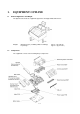
1. 1.1 EQUIPMENT OUTLINE External Appearance and Weight The figure below shows the equipment appearance and approximate dimensions. Weight: 1.2 Machine proper (excluding a ribbon cartridge) In package Components The equipment consists of the following major components: I-1 Approx. 4 kg (8.82 lbs.) Approx. 6 kg (13.23 lbs.
2.
Model Name Engine Color Transmission Speed (sec) Modem Speed (bps) Group Compatibility Input/Output Width ADF (pages) Recording Paper Loadable Ribbon Life (Letter-size print) Starter Ribbon Life (Letter-size print) LCD Size On-Screen Programming Super Fine Smoothing Gray Scale (levels) One Touch Speed Dial Telephone Index Speaker Phone Handset FAX/TEL Switch Distinctive Ring Detection* Caller ID* Call Waiting Caller ID* TAD Interface Enhanced Remote Activation Automatic Redial Next-FAX Reservation Multi-Res
Model Name Engine Color Transmission Speed (sec) Modem Speed (bps) Group Compatibility Input/Output Width ADF (pages) Recording Paper Loadable Ribbon Life (A4-size print) Starter Ribbon Life (A4-size print) LCD Size On-Screen Programming Super Fine Smoothing Gray Scale (levels) One Touch Speed Dial Telephone Index Speaker Phone Handset FAX/TEL Switch Caller ID Call Waiting Caller ID Distinctive Ringing TAD Interface Enhanced Remote Activation Automatic Redial Next-FAX Reservation Multi-Resolution Transmissi
Model Name Engine Color Transmission Speed (sec) Modem Speed (bps) Group Compatibility Input/Output Width ADF (pages) Recording Paper Loadable Ribbon Life (A4-size print) Starter Ribbon Life (A4-size print) LCD Size On-Screen Programming Super Fine Smoothing Gray Scale (levels) One Touch Speed Dial Telephone Index Speaker Phone Handset FAX/TEL Switch Caller ID Call Waiting Caller ID Distinctive Ringing TAD Interface Enhanced Remote Activation Automatic Redial Next-FAX Reservation Multi-Resolution Transmissi
CHAPTER II.
CHAPTER III.
CONTENTS 1. OVERVIEW ............................................................................................................... III-1 2. MECHANISMS .......................................................................................................... III-2 2.1 Transmitting Mechanism (Feeding and scanning documents) ......................... III-2 2.1.1 Automatic document feeder (ADF) ........................................................... III-2 2.1.2 Scanner .................................
1. OVERVIEW *Not provided on the FAX-910.
2. MECHANISMS The facsimile equipment is classified into the following mechanisms: n Transmitting Mechanism Feeding and scanning documents n Receiving Mechanism Feeding paper and printing data n Power Transmission Mechanism Switching the power transmission route n Sensors and Actuators 2.
2.1.2 Scanner The scanner uses a contact image sensor (CIS) unit which consists of an LED array illuminating documents, a self-focus lens array collecting the reflected light, a CIS PCB carrying out photoelectric conversion to output picture element data, and a cover glass on which a document advances. When the document passes between the document pressure bar and the cover glass, it is scanned.
2.2 Receiving Mechanism (Feeding paper and printing data) The receiving mechanism consists of the recording paper cover ASSY, paper feed roller ASSY, platen, thermal recording head, paper ejection roller, and sensors. (For details about the sensors, refer to Section 2.4.) STEP 1: In the paper feeding mode If the equipment receives data, the control electronics activates the solenoid and rotates the motor counterclockwise to drive the paper feed roller (and paper ejection roller).
2.3 Power Transmission Mechanism The equipment has a single drive motor whose power transmission route can be switched by the planetary gear systems and the solenoid. This switching allows the equipment to function in four operation modes (scanning, paper feeding/ejecting, recording, and copying modes). For the details about the planetary gear systems, refer to Subsection 2.3.2. 2.3.1 Structure of the gear train All of the motor and gears are located at the left side of the equipment.
2.3.2 Description of planetary gear system The equipment uses the following three planetary gear systems: - Sun gear 24/90 ("B" in the figure given on the previous page) and its planet gears - Sun gear 65/60 ("K") and its planet gear - Sun gear 24/28 ("O") and its planet gear This section describes the planetary gear system of sun gear 24/90 ("B"). It consists of sun gear 24/90, two planet gears 34, arm A, and arm B as shown below.
2.3.3 Power transmission for four operation modes Depending upon the solenoid ON/OFF state and the motor rotation direction, the planetary gear train switches the power transmission route for the four operation modes.
[1] Scanning mode (Solenoid: OFF, Motor rotation: Reverse) In the scanning mode, the control electronics deactivates the solenoid. When the motor rotates in the reverse direction, the clutch lever turns counterclockwise with the compression spring so that its cutout becomes engaged with the stopper of arm A. Once arm A is locked, planet gear 34A ("J") will not be engaged with any other gear but simply idle.
[2] Paper feeding/ejecting mode (Solenoid: ON, Motor rotation: Reverse) In the paper feeding/ejecting mode, the control electronics activates the solenoid to release the stopper of arm A. When the motor rotates in the reverse direction, sun gear 24/90 ("B") rotates clockwise so that planet gear 34A ("J") transmits the torque via sun gear 65/60 ("K") and other gears to the paper feed roller gear ("T") and paper ejection roller gear ("R").
[3] Recording mode (Solenoid: OFF, Motor rotation: Forward) In the recording mode, the control electronics deactivates the solenoid. When the motor rotates in the forward direction, the clutch lever turns counterclockwise with the compression spring so that its cutout becomes engaged with the stopper of arm A. Once arm A is locked, planet gear 34A ("J") will not be engaged with any other gear but simply idle.
Active Gears on the Inner Side of the Drive Unit III - 11
[4] Copying mode (Solenoid: ON, Motor rotation: Forward) In the copying mode, the control electronics activates the solenoid to release the stopper of arm A from the clutch lever. When the motor rotates in the forward direction, sun gear 24/90 ("B") rotates counterclockwise so that planet gear 34A ("J") transmits the torque to the document scanner mechanism (e.g.
Active Gears on the Inner Side of the Drive Unit III - 13
2.3.4 Power transmission route Rotation of the motor gear is transmitted as shown below.
[1] Scanning Mode (Solenoid: OFF, Motor rotation: reverse) [2] Paper Feeding/Ejecting Mode (Solenoid: ON, Motor rotation: reverse) [3] Recording Mode (Solenoid: OFF, Motor rotation: forward) [4] Copying Mode (Solenoid: ON, Motor rotation: forward) III - 15
2.4 Sensors and Actuators This equipment has five photosensors and two mechanical switches as described below.
Location of Sensors and Actuators (1) III - 17
*Not provided on the FAX-910.
3. CONTROL ELECTRONICS 3.1 Configuration The hardware configuration of the facsimile equipment is shown below. *1 On the main PCB are these sensors: l Ribbon sensor (PI1) l Document rear sensor (PI2) l Cover sensor (SW1) *2 On the front document sensor PCB is the front document sensor. *3 On the sensor PCB are these sensors: l Paper-edge sensor (PH1) l Paper ejection sensor (PH2) *4 On the hook switch PCB* is the hook switch sensor (SW1). *Not provided on the FAX-910.
3.2 Main PCB The main PCB, which is the nucleus controlling the entire operation of the equipment, consists of a FAX engine (ASIC), memories, motor drive circuitry, sensor detection circuitry, and analog circuits for scanning, recording, and power transmission shifting. *Provided on the FAX870MC/FAX-930/FAX-931/MFC970MC.
FAX750/FAX770/FAX-910/FAX-920/FAX-921/MFC-925 FAX870MC/FAX-930/FAX-931/MFC970MC III - 21
3.3 NCU PCB The NCU PCB switches the communications line to telephone or built-in MODEM, under the control of the main PCB. U.S.A.
European versions NOTE: For models equipped with a power failure phone, the circuit enclosed in a dotted line does not apply and points A and B are short circuited together.
3.4 Control Panel PCB The control panel PCB and the main PCB communicate with each other by serially transmitting commands and data. The control panel unit consists of a gate array, an LCD and LEDs, which are controlled by the gate array according to commands issued from the FAX engine on the main PCB. The calendar clock is backed up by the backup circuit on the main PCB. The panel FPC is a flexible keyboard PCB which integrates the key matrix having rubber keytops.
3.5 Power Supply PCB The power supply uses the switching regulator to generate DC power (+25V, +6.5V, and +5V) from a commercial AC power line. The +25V source is stabilized and fed to the motor and solenoid (for feeding documents, recording paper, and ink ribbon), recording head, the main PCB, and the CIS LED array. The +6.5V source is not stabilized and fed to the Ni-MH battery (on the FAX870MC/FAX-930/FAX931/MFC970MC).
CHAPTER IV.
CONTENTS 1. DISASSEMBLY/REASSEMBLY ............................................................................... IV-1 n Safety Precautions .................................................................................................. IV-1 Tightening Torque List ............................................................................................ IV-2 2. n Preparation..............................................................................................................
1. DISASSEMBLY/REASSEMBLY n Safety Precautions To prevent the creation of secondary problems by mishandling, observe the following precautions during maintenance work. (1) Unplug the power cord from the power outlet before replacing parts or units. When having access to the power supply, be sure to unplug the power cord from the power outlet. (2) Be careful not to lose screws, washers, or other parts removed for parts replacement.
Tightening Torque List Location Screw type Q'ty Tightening torque (kg•cm) Loosening torque (kg•cm) ADF parts Panel rear cover Document front sensor PCB Control panel PCB* Taptite, pan (washer) B M3x6 Taptite, cup B M3x8 Taptite, cup B M2.6x6 Taptite, cup B M2.6x6 1 2 1 1 4 ±2 4 ±2 4 ±2 4 ±2 Min. 1 Min. 1.5 Min. 1 Min. 1 LF leaf spring Taptite, bind B M3x8 1 5 ±2 Min. 2 CIS holders CIS unit Taptite, bind B M3x8 Taptite, pan B M3x8 2 1 4 ±1 5 ±2 Min. 2 Min.
n Preparation Prior to proceeding to the disassembly procedure, (1) Unplug - the modular jack of the telephone line, - the modular jack of the curled cord (and remove the handset), and - the modular jack of an external telephone set if connected. (Not shown below.) (2) Remove - n the document wire extension, the paper wire extension, the paper support, and the ribbon cartridge.
n Disassembly Order Flow IV - 4
1.1 ROM Cover, Battery ASSY* and Ribbon Shaft Stopper (*FAX870MC/FAX-930/FAX-931/MFC970MC) (1) Open the control panel ASSY to the front. (2) Pull up the lock levers and open the recording paper cover ASSY to the rear. (3) As shown below, insert the tip of the spring hook at the center or right half of the locking arm (when viewed from the front), then lift up the hook to release and move the ROM cover to the right.
(5) Remove the ribbon shaft stopper by pushing down the rear end of the stopper lightly with a screwdriver. n Reassembling Notes • When reinstalling the ribbon shaft stopper, lightly push down the ribbon shaft stopper spring with the rear end of the ribbon shaft stopper and then set the stopper.
1.2 Control Panel ASSY (1) Open the control panel ASSY to the front. (2) Push the right arm of the panel rear cover outward (in the direction of arrow •) to release it from the boss provided on the main frame, then move the control panel ASSY to the left and push the left arm outward (in the direction of arrow ‚). (3) Remove the harness holder by unhooking its latches from the panel rear cover with a flat screwdriver as shown below.
(4) Disconnect the panel-main harness.
1.3 Panel Rear Cover and Control Panel (1) Place the control panel ASSY upside down. If you do not need to remove the ADF parts, document pressure bar, or document ejection roller, skip to step (6). (2) To remove the ADF parts (spring covers, spring plates, and separation rubber), remove the screw. (3) To remove the document pressure bar ASSY, pull either of the supports provided on the panel rear cover outwards and lift up the pressure bar. The spring also comes off.
(4) To disassemble the document pressure bar ASSY, first remove the white film. NOTE: Once removed, the white film will become unusable and a new one will have to be put back in. Next, place the document pressure bar ASSY with the pressure bar support facing up for easier disassembly. While pressing the boss of the document pressure bar with the tip of a Phillips screwdriver, shift the document pressure bar to the right to take it off from the pressure bar support.
(5) To remove the document ejection roller, push the arm rib to the rear and shift the document ejection roller to the right. Pull out the document ejection roller gear and remove gear 37. Pull out the document ejection roller to the left. Remove the bearing. (6) Remove the two screws from the panel rear cover. (See the next page.) (7) Unhook the panel rear cover from the four "X" latches provided on the control panel and lift up the panel rear cover.
IV - 12
(11) To remove the LCD, unhook the four "Z" latches of the LCD holder from the control panel PCB. Unlock the LCD cable connector and disconnect the LCD flat cable. Slide the LCD to the cable side and remove it from the LCD holder. NOTE: Do not take out the LCD except when the LCD is defective and requires replacement. (12) Unlock the FPC key connector and disconnect the FPC key. n Reassembling Notes • A new LCD is covered with a protection sheet. Before installing it, remove the protection sheet.
1.4 LF Roller ASSY and CIS Unit (1) Take off the LF leaf spring by removing the screw. (2) Push the arm rib to the rear and shift the LF roller ASSY to the left. The bearing also comes off.
(3) Peel off the black CIS film. NOTE: Once removed, the CIS film will become unusable and a new one will have to be put back in.
(4) Remove screw "a" from the CIS holder L. (5) Lift up the left end of the CIS unit slightly and disengage the CIS holder R from the hooks provided of the main frame. (6) Disconnect the CIS-main harness. (7) Take off the CIS holders L and R by removing screws "b.
(8) Push the latch to the rear and remove the document pressure rollers and their shaft. (9) Remove the document pressure roller spring. n Reassembling Notes • When attaching the CIS film, align its right and rear edges with the cutout provided in the main frame, as illustrated on page IV-15. • Before reinstalling the LF roller ASSY, apply grease to the left end of the ASSY. (Refer to Section 2, "LUBRICATION.
1.5 Head Protector, Recording Head ASSY, Head Adjuster, and Recorder Frame (1) Pull up the lock levers and open the recording paper cover ASSY to the rear. (2) While pulling up the left end of the head protector, unhook latches • through „ in this order with a small flat screwdriver as illustrated below.
(3) Push down both ends of the recording head ASSY and move it to the rear to release the tabs from the cutouts provided in the recorder frame. (4) Disconnect the two harnesses (main-head harness and head-power harness) from the recording head ASSY and then lift up the ASSY. (5) Remove the three head springs.
(6) Take off the recorder frame by removing the two screws. (7) Remove the grounding spring. (8) Take out the head-power harness from the hook provided on the main frame.
(9) To replace the main frame with a new one, first check to see which position the head adjuster is currently set in (see the three positions in the illustration below), and then remove the head adjuster with a flat screwdriver. Next set it to the new main frame in the same position. If the printed image is abnormally light or dark, remove the head adjuster and set it back in any other position. NOTE: Do not access the head adjuster unless necessary.
1.6 Recording Paper Cover ASSY and Paper Guides* (*Not provided on the U.S.A. and Canadian versions.) (1) To remove the paper guides*, open the paper front cover towards you, then pull up the latch (in the direction of arrow • in the illustration below) and pull the paper guide in the direction of arrow ‚. (2) Remove the two screws. (3) Lift up the front of the recording paper cover ASSY and take it out to the rear.
1.7 Lock Levers, Chute B ASSY, Gears, Paper Ejection Roller, Paper Feed Roller ASSY, Pressure Plate, Paper Feed Chute and Other Components on the Platen Frame With the platen frame being secured to the main frame, you can remove and install the components given in this section. To remove the platen frame itself, see Section 1.8. (1) Open the platen frame ASSY. (2) Turn the lock levers R and L to the rear and pull them out.
(3) Pull the chute B ASSY up and towards you to unhook the upper latches from the platen frame, then pull the ASSY down and towards you to unhook the lower latches.
(4) At the left end of the platen frame, remove the gears in the following order: - Platen gear (gear 25/27) by pulling its pawl outwards. (Also remove the black platen shaft bushing L.) - Arm P ASSY by pulling its pawl outwards. - Gear 24/28 (sun gear) - Clutch gear 37 ASSY by removing the retaining ring, together with gear 19/38 - Paper ejection roller gear NOTE: The platen shaft bushing is greased for antistatic purpose. Take care not to stain other parts with the grease.
(6) Remove the front cover sensing actuator from the paper feed roller shaft by pulling up the actuator's rear edge as shown below. (7) At the right end of the paper feed roller ASSY (when viewed from the rear), remove the collar stopper and gear 43 ASSY by removing the retaining ring. (8) At the left end (when viewed from the rear), remove the pawled bushing by pulling its pawls outwards.
(9) Make sure that the platen is set in place, and then close the platen frame ASSY. NOTE: If you close the platen frame ASSY when no platen is set and the recording head ASSY is installed, the platen frame ASSY and the recording head ASSY will be locked together. (10) Fully turn the pressure plate release cam to the rear and pull it up and outwards to unhook from the platen frame. (11) Pull the latches provided on the pressure plate outwards and lift it up. The two springs also come off.
(12) Pull up the separation pad while squeezing it. The spring also comes off. (13) Remove the paper-edge sensor actuator by pulling the support outwards.
(14) To take the paper feed chute off the platen frame, do the following: - Disconnect the main-sensor harness from the sensor PCB while pressing down the PCB with your finger, then remove the harness guide and take out the harness from the cable clamps. NOTE: Pulling up the main-sensor harness without pressing down the sensor PCB will cause the PCB to work out of the paper feed chute. NOTE: Once removed, the harness guide will become unusable and a new one will have to be put back in.
- Remove the two screws and lift up the paper feed chute.
(15) From the paper feed chute, remove the pressure plate link, paper ejection sensor actuator, sensor PCB, and chute film. NOTE: Once removed, the chute film will become unusable and a new one will have to be put back in.
IV - 32
(16) Remove the platen as follows: At the left end of the platen frame, remove the platen gear (gear 25/27) by pulling its pawl outwards and then remove the platen shaft bushing L. At the right end, remove the platen shaft bushing R by pulling its pawls outwards. Move the platen to the left to take out the right end from the platen frame and then take it out to the right. CAUTION: After removing the platen, NEVER close the platen frame ASSY when the recording head ASSY is set in place.
1.8 Cover Stopper and Platen Frame ASSY TIP: Only when you need to remove the platen frame from the main frame, remove the cover stopper. When accessing other components, keep the cover stopper in place for easier handling. (1) Remove the screw from the cover stopper. (2) Lift up the rear end of the cover stopper and open the platen frame ASSY to remove the cover stopper. (3) Take out the cover stopper spring plate.
(4) Remove the retaining ring (E5) from the left end of the platen frame and move the frame to the left. The spring washer also comes off. NOTE: Take care not to drop the retaining ring inside the main frame. If you drop it, you need to remove the bottom plate to take it out.
1.9 Bottom Plate (1) Place the machine upside down. (2) Remove the seven screws from the bottom plate. (3) Slightly lift up the bottom plate and disconnect the grounding terminal. (4) Remove the bottom plate together with the insulation sheet.
1.10 Power Supply PCB, Main PCB, and NCU PCB (1) Unhook the head-power harness from latch "B" (together with the PC I/F modular harness since the head-power harness is routed under the PC I/F modular harness through the duct when viewed from the bottom). (2) Pull out the AC cord bushing from the main frame. (3) Disconnect the power supply PCB from the main PCB. (4) Slightly lift up the power supply PCB and disconnect the head-power harness.
IV - 38
n Reassembling Notes • • When routing the harnesses, refer to Section 1.17. After you replace the main PCB, be sure to follow the flowchart given below.
1.11 Speaker, PC I/F Modular ASSY, and Ribbon Shaft Stopper Spring (1) Pull the speaker support spring to the right and lift up the speaker. The spring also comes off. (2) Slightly lift up the main PCB (if mounted) and disconnect the speaker harness from the PCB. (3) Unhook the PC I/F modular harness (which is routed through the duct) from latches “B” and “A,” and then take out the modular. (4) Slightly lift up the main PCB (if mounted) and disconnect the PC I/F modular harness from the PCB.
1.12 Drive Unit, Motor, and Main-Head Harness (1) Slightly lift up the main PCB (if mounted), unhook the motor harness from latch "D," and disconnect the harness from the PCB. (2) Slightly lift up the main PCB (if mounted), unhook the solenoid harness from latches "E" and “G” and the notch, then disconnect the harness from the PCB. (3) Lift up the drive unit. (4) Remove the motor from the drive unit by removing the screw.
1.13 Panel-lock Leaf Springs (1) Remove the panel-lock leaf springs by pushing them up with your finger from the bottom.
1.14 Cover Sensor Actuators and Pinch Roller (1) Pull up the cover sensor actuator A and turn it to separate from the actuator B. The spring pops up and the actuator B drops. (2) Remove the harness guide film. NOTE: This film is attached to the main frame with double-sided adhesive tape. This film can be usable again as long as it is adhesive. (3) Press the lock of each pinch roller spring and pull out the springs to the rear. (4) Lift up the pinch roller.
1.15 Document Rear Sensor Actuator, Separation Roller, and Ribbon Sensor Actuator (1) Turn up the document rear sensor actuator to the front and pull it up. (2) Push lock "a" (in the direction of arrow •) and pull the separation roller gear to the right (in the direction of arrow ‚). Then take out the separation roller and its gear. (3) To remove the ribbon sensor actuator, you need to disengage the recording head ASSY from the recorder frame. (Refer to Section 1.5, (1) to (3).
1.16 Handset Mount,* Hook Switch PCB,* and Dummy Mount** (*For models except the FAX-910, **For the FAX-910 only) (1) Insert the tip of a flat screwdriver into the slits of the handset mount* (or the dummy mount**) and unhook the mount from the main frame. (2) To replace the hook switch PCB*, you need to disconnect the hook switch harness from the main PCB. (Refer to Section 1.10.
1.
2. LUBRICATION Apply the specified lubricants to the lubrication points as shown below. Molykote EM-30L or EM-30LG For points , apply a rice-sized pinch of grease (6 mm3). Floil GE-334C For points [1] , apply half of a rice-sized pinch of grease (3 mm3).
IV - 48
[2] LF roller ASSY [3] Platen frame ASSY IV - 49
IV - 50
[4] Separation roller and main frame IV - 51
CHAPTER V.
CONTENTS 1. ENTRY INTO THE MAINTENANCE MODE ............................................................ V-1 2. LIST OF MAINTENANCE-MODE FUNCTIONS ...................................................... V-2 3. DETAILED DESCRIPTION OF MAINTENANCE-MODE FUNCTIONS .................. V-4 3.1 EEPROM Parameter Initialization .................................................................. V-4 3.2 Printout of Scanning Compensation Data ...................................................... V-5 3.
1. ENTRY INTO THE MAINTENANCE MODE FAX750/FAX770/FAX870MC/MFC970MC: To make the facsimile equipment enter the maintenance mode, press the Function, *, 2, 8, 6, and 4 keys in this order. Within 2 seconds FAX-910/FAX-920/FAX-921/FAX-930/FAX-931/MFC-925: To make the facsimile equipment enter the maintenance mode, press the Menu, *, 2, 8, 6, and 4 keys in this order. Within 2 seconds " on the The equipment beeps for approx.
2. LIST OF MAINTENANCE-MODE FUNCTIONS Maintenance-mode Functions Function Code 01 Reference Subsection (Page) Function EEPROM Parameter Initialization 3.1 (V-4) Printout of Scanning Compensation Data 3.2 (V-5) 08 ADF* Performance Test 3.3 (V-7) 09 Test Pattern 1 3.4 (V-8) 10 Firmware Switch Setting 3.5 (V-9) 11 Printout of Firmware Switch Data 3.5 (V-49) 12 Operational Check of LCD 3.6 (V-50) 13 Operational Check of Control Panel PCB (Check of Keys and Buttons) 3.
-------------------------- IMPORTANT - - - - - - - - - - - - - - - - - - - - - - - - - - - - - - - - Basically, the maintenance-mode functions listed on the previous page should be accessed by service personnel only. However, you may allow end users to access some of these under the guidance of service personnel (e.g., by telephone). The user-accessible functions (codes 10, 11, 12, 82, 87 and 91) are shaded in the table given on the previous page.
3. DETAILED DESCRIPTION OF MAINTENANCE-MODE FUNCTIONS 3.1 n EEPROM Parameter Initialization Function The equipment initializes the parameters, user switches, and firmware switches registered in the EEPROM, to the initial values. Entering the function code 01 initializes all of the EEPROM areas, but entering 91 does not initialize some areas, as listed below.
3.2 n Printout of Scanning Compensation Data Function The equipment prints out the white and black level data for scanning compensation. n Operating Procedure Do not start this function merely after powering on the equipment but start it after carrying out a sequence of scanning operation. Unless the equipment has carried out any scanning operation, this function cannot print out correct scanning compensation data.
Scanning Compensation Data List V-6
3.3 n ADF Performance Test Function The equipment counts the documents fed by the automatic document feeder (ADF) and displays the count on the LCD for checking the ADF performance. n Operating Procedure (1) Set documents (Allowable up to the ADF capacity) in the initial stage of the maintenance mode. The "DOC. READY" will appear on the LCD. (2) Press the 0 and 8 keys in this order. The equipment i) copies the 1st document and displays “COPY P.01 STD” on the LCD.
3.4 n Test Pattern 1 Function This function, much like the copying function, prints out test pattern 1 to allow the service personnel to check for record data missing or print quality. n Operating Procedure Press the 0 and 9 keys in this order in the initial stage of the maintenance mode. The figure below shows test pattern 1.
3.5 Firmware Switch Setting and Printout [ A ] Firmware switch setting n Function The facsimile equipment incorporates the following firmware switch functions (WSW01 through WSW36) which may be activated with the procedures using the control panel keys and buttons. The firmware switches have been set at the factory in conformity to the communications standards and codes of each country. Do not disturb them unless necessary. Some firmware switches may not be applicable in some versions.
n Operating Procedure (1) Press the 1 and 0 keys in this order in the initial stage of the maintenance mode. The equipment displays the "WSW00" on the LCD and becomes ready to accept a firmware switch number. (2) Enter the desired number from the firmware switch numbers (01 through 36). The following appears on the LCD: WSWXX = 0 0 0 0 0 0 0 0 (3) Use the and keys to move the cursor to the selector position to be modified. (4) Enter the desired number using the 0 and 1 keys. (5) Press the Set key.
n Detailed Description for the Firmware Switches WSW01 (Dial pulse setting) Selector No. Function Setting and Specifications Dial pulse generation mode No. 1 0 0 1 1 2 0 1 0 1 : : : : N N+1 10-N N Break time length in pulse dialing No. 3 0 0 1 1 4 0 1 0 1 : : : : 60 ms 67 ms 40 ms (for 16 PPS) 64 ms (at 106-ms intervals) Inter-digit pause No.
l Selector 7: Switching between pulse (DP) and tone (PB) dialing, by the function switch This selector determines whether or not the dialing mode may be switched between the pulse (DP) and tone (PB) dialing by using the function switch. l Selector 8: Default dialing mode, pulse (DP) or tone (PB) dialing This selector sets the default dialing mode (pulse dialing or tone dialing) which may be changed by the function switch.
WSW03 (PABX* mode setting) Selector No. 1 Function Setting and Specifications CNG detection when sharing a modular wall socket with a telephone 0: No. 2 0 0 0 0 1 1 1 1 2 | 4 Min. detection time length of PABX* dial tone, required for starting dialing 5 CNG detection when sharing a modular wall socket with a telephone 0: A 3 0 0 1 1 0 0 1 1 0 1 Dial tone detection in PABX* 1 0 7 1 1 8 4 0 1 0 1 0 1 0 1 : : : : : : : : A No. 6 7 0 0 6 1: 50 ms 210 ms 500 ms 800 ms 900 ms 1.5 sec. 2.0 sec.
l Selectors 6 and 7: Dial tone detection in PABX These selectors activate or deactivate the dial tone detection function which detects a dial tone when a line is connected to the PABX. Setting both of these selectors to “1” activates the dial tone detection function so that the equipment starts dialing upon detection of a dial tone when a line is connected. Other setting combinations deactivate the dial tone detection function so that the equipment starts dialing after the specified WAIT (3.5, 5.0, or 7.
WSW04 (TRANSFER facility setting) Selector No. 1 Function Setting and Specifications Earth function in transfer facility 2 3 Dual tone detection frequency in ICM recording 4 Tone detection sensitivity in ICM recording 5 6 7 8 Earth time length for earth function Break time length for flash function 0: Provided No. 2 0 0 1 3 0 1 x : : : 0: OFF 1: Not provided 350 and 440 Hz (A) 440 and 480 Hz (B) 480 and 620 Hz (C) 1: High No. 5 0 0 1 1 6 0 1 0 1 : : : : 200 ms 300 ms 500 ms 700 ms No.
WSW05 (1st dial tone and busy tone detection) Selector No. Function 1 | 3 1st dial tone detection 4 Max. pause time allowable for remote ID code detection 5 6 Setting and Specifications No. 1 0 0 0 0 1 1 1 1 Busy tone detection in automatic receiving mode 8 Not used. 3 0 1 0 1 0 1 0 1 : : : : : : : : 0 : 2 seconds No. 5 0 0 1 1 Busy tone detection in automatic sending mode 7 2 0 0 1 1 0 0 1 1 6 0 1 0 1 : : : : 0 : Yes 3.5 sec. WAIT 7.0 sec. WAIT 10.5 sec. WAIT 14.0 sec. WAIT 17.5 sec.
l Selector 4: Max. pause time allowable for remote ID code detection This selector sets the maximum pause time allowable for detecting the second digit of a remote ID code after detection of the first digit in remote reception. If selector 4 is set to "0" (2 seconds), for instance, only a remote ID code whose second digit is detected within 2 seconds after detection of the first digit will become effective so as to activate the remote function.
WSW06 (Pause key setting and 2nd dial tone detection) Selector No. Function Setting and Specifications 1 | Pause key setting and 2nd dial tone detection No. 1 0 0 0 0 1 1 2 0 0 1 1 0 1 3 0 1 0 1 0 0 : : : : : : 3 1 0 1 : 1 1 1 : No. 4 0 0 0 0 1 1 1 1 4 | Detection of international tone 6 7 8 No. of 2nd dial tone detection times 2nd dial tone interrupt detecting time 5 0 0 1 1 0 0 1 1 6 0 1 0 1 0 1 0 1 : : : : : : : : No pause 3.5 sec. WAIT 7 sec. WAIT 10.5 sec. WAIT 14 sec.
l Selectors 1 through 3: Pause key setting and 2nd dial tone detection Selectors 1 2 3 l 0 0 0 No WAIT is inserted even if the Pause key is pressed. 0 0 0 1 0 1 1 0 1 0 1 0 If you press the Pause key during dialing, the facsimile equipment will insert WAIT as defined in the above table. If the Pause key is pressed repeatedly, the equipment inserts the specified WAIT multiplied by the number of depressions. It applies also in hook-up dialing.
WSW07 (Dial tone setting 1) Selector No. Function Setting and Specifications No. 1 2 1 Frequency band range 2 3 Line current detection 0 0 : Narrows by 10 Hz 0 1 : Initial value 1 X : Widens by 10 Hz 0: No 1: Yes No. 4 5 6 4 | 6 2nd dial tone detection level (Z = 600 Ω) 7 1st dial tone interrupt detecting time 8 Not used.
WSW08 (Dial tone setting 2) Selector No. 1 | 3 4 5 6 | 8 Function Setting and Specifications 1st dial tone detection time length Time-out length for 1st and 2nd dial tone detection Detection level of 1st dial tone and busy tone before dialing No. 1 0 0 0 0 1 1 1 1 2 0 0 1 1 0 0 1 1 3 0 1 0 1 0 1 0 1 No. 4 0 0 1 1 5 0 1 0 1 : 10 sec. : 20 sec. : 15 sec. : 30 sec. No. 0 0 0 0 1 1 1 1 7 0 1 0 1 0 1 0 1 8 : : : : : : : : 6 0 0 1 1 0 0 1 1 : : : : : : : : 50 ms 210 ms 500 ms 800 ms 900 ms 1.
WSW09 (Protocol definition 1) Selector No. Function Setting and Specifications 1 Frame length selection 0: 256 octets 1: 64 octets 2 Use of non-standard commands 0: Allowed 1: Prohibited No. 3 0 0 1 1 3 No. of retries 4 4 0 1 0 1 : : : : 4 times 3 times 2 times 1 time 5 T5 timer 0: 300 sec. 1: 60 sec. 6 T1 timer 0: 35 sec. 1: 40 sec. 7 8 Elapsed time for time-out control for no response from the called station in automatic sending mode No.
WSW10 (Protocol definition 2) Selector No. Function Setting and Specifications 1 Switching of DPS, following the CML ON/OFF 0: No 1: Yes 2 Time length from transmission of the last dial digit to CML ON 0: 100 ms 1: 50 ms 3 Time length from CML ON to CNG transmission 0: 2 sec. 1: 4 sec. 4 Time length from CML ON to CED transmission (except for facsimileto-telephone switching) 0: 0.5 sec. 1: 2 sec. No. 5 6 7 8 l Selector 1: No.
WSW11 (Busy tone setting) Selector No. Function Setting and Specifications No. 1 2 Frequency band range 3 Not used. 4 5 6 1 0 0 1 2 0 1 x : : : Narrows by 10 Hz Initial value Widens by 10 Hz 1: 400-600/400-600 ms ON/OFF time length ranges (More than one setting allowed) 1: 175-440/175-440 ms 1: 700-800/700-800 ms 7 1: 110-410/320-550 ms 8 1: 100-660/100-660 ms NOTE: WSW11 is not applicable in those countries where no busy tone detection is supported.
WSW12 (Signal detection condition setting) Selector No. 1 2 3 4 Function Setting and Specifications Min. OFF time length of calling signal (Ci) No. 1 0 0 1 1 2 0 1 0 1 : : : : 1500 ms 500 ms 700 ms 900 ms Max. OFF time length of calling signal (Ci) No. 3 0 0 1 1 4 0 1 0 1 : : : : 6 sec. 7 sec. 9 sec. 11 sec. Detecting time setting No. 5 0 0 1 1 6 0 1 0 1 : : : : 800 ms (1000 ms*) 200 ms 250 ms 150 ms 5 6 7 Delay 8 Not used. 0: Yes 1: No * 1000 ms in Chinese versions.
WSW13 (Modem setting) Selector No. 1 2 3 4 5 | 8 Function Setting and Specifications Cable equalizer No. 1 0 0 1 1 2 0 1 0 1 : : : : 0 km 1.8 km 3.6 km 5.6 km Reception level No. 3 0 0 1 1 4 0 1 0 1 : : : : -43 dBm -47 dBm -49 dBm -51 dBm 0: 0: 0: 0: Modem attenuator 0 dB 0 dB 0 dB 0 dB 1: 1: 1: 1: 8 dB 4 dB 2 dB 1 dB The modem should be adjusted according to the user's line conditions.
WSW14 (AUTO ANS facility setting) Selector No. Function Setting and Specifications No. 1 2 Frequency band selection (Lower limit) No. 3 4 Frequency band selection (Upper limit) No. 5 | 8 l No.
WSW15 (REDIAL facility setting) Selector No. Function Setting and Specifications 1 Selection of redial interval 2 3 | 6 No. of redialings No. 1 0 0 1 1 2 0 1 0 1 : : : : 5 minutes 1 minute 2 minutes 3 minutes No. 3 0 0 0 0 4 0 0 0 0 5 0 0 1 1 6 0 1 0 1 : : : : 1 1 1 1 : | l 7 Redialing for no response sent from the called terminal 8 Not used. Selectors 1 through 6: 0: Redialing 1: 16 times 1 times 2 times 3 times | 15 times No redialing Selection of redial interval and No.
WSW16 (Function setting 1) Selector No. l Function Setting and Specifications 1 Not used. 2 CCITT superfine recommendation 3 | 6 Not used. 7 8 Selector 2: 0: OFF 1: ON Max. document length limitation 0: 400 cm 1: 90 cm Stop key pressed during reception 0: Not functional 1: Functional CCITT superfine recommendation If this selector is set to "1," the equipment communicates in CCITT recommended superfine mode (15.4 lines/mm). If it is set to "0," it communicates in native superfine mode.
WSW17 (Function setting 2) Selector No. Function Setting and Specifications No. 1 0 0 1 1 2 Off-hook alarm 2 0 1 X : : : No alarm Always valid Valid except when 'call reservation' is selected. 3 Power failure report output 0: ON 1: OFF 4 Calendar clock/prompt alternate display 0: NO 1: YES 5 Calendar clock type 0: U.S.A. type 1: European type 6 Error indication in activity report 0: NO 1: YES 7 Non-ring reception 0: OFF 1: ON 8 Not used.
WSW18 (Function setting 3) Selector No. 1 2 3 4 5 6 Function Setting and Specifications Not used. Detection enabled time for CNG and no tone No. 2 0 0 1 1 3 0 1 0 1 : : : : Not used. Registration of station ID 0: 7 Permitted No. 7 0 1 8 X 0 : : 1 1 : Tone sound monitoring 8 l 40 sec. 0 sec. (No detection) 5 sec. 80 sec.
WSW19 (Transmission speed setting) Selector No. Function Setting and Specifications 1 | 3 First transmission speed choice for fallback 4 | 6 Last transmission speed choice for fallback 7 Not used. 8 V. 17 mode • No. 1 No.
WSW20 (Overseas communications mode setting) Selector No. Function Setting and Specifications 1 EP* tone prefix 0: OFF 1: ON 2 Overseas communications mode (Reception) 0: 2100 Hz 1: 1100 Hz 3 Overseas communications mode (Transmission) 0: OFF 1: Ignores DIS once. 4 5 Min. time length from reception of CFR to start of transmission of video signals No. No.
WSW21 (TAD setting 1) Selector No. 1 | 5 Function Setting and Specifications Max. waiting time for voice signal No. 1 0 0 0 0 2 0 0 0 0 3 0 0 0 0 4 0 0 1 1 5 0 1 0 1 0 0 0 1 1 | 0 1 | 6 Two-way recording 7 8 Erasure of message stored in the memory after the message transfer 1 1 1 No. 6 0 0 1 1 7 0 1 0 1 : : : : : : : : No detection 1 sec. 2 sec. 3 sec. | : 8 sec. | : 31 sec. For U.S.A. Except for U.S.A.
WSW22 (ECM and caller ID setting) Selector No. Function Setting and Specifications 1 ECM* in sending 0: ON 1: OFF 2 ECM* in receiving 0: ON 1: OFF 3 Call Waiting Caller ID 0: ON 1: OFF 4 Not used. 0: 0: 0: 0: 1: 1: 1: 1: 5 | 8 Acceptable TCF bit error rate (%) (Only at 4800 bps) 0% 0% 0% 0% 8% 4% 2% 1% * ECM: Error correction mode NOTE: Selector 3 is applicable to the U.S.A. versions only. NOTE: Selectors 5 through 8 are applicable to the Chinese, Taiwanese and Asian versions only.
WSW23 (Communications setting) Selector No. 1 Function Setting and Specifications Starting point of training check (TCF) 0: From the head of a series of zeros 1: From any arbitrary point No. 2 0 0 1 1 3 0 1 0 1 : : : : 0% 0.5% 1% 2% Decoding error rate for transmission of RTN 4 0 0 1 1 5 0 1 0 1 : : : : 16% 14% 10% 8% 6 Issue of RTN at the occurrence of a pagination error 0: YES 1: 7 Not used. 8 Limitation of attenuation level 0: YES 1: NO 2 Allowable training error rate 3 No.
WSW24 (TAD setting 2) Selector No. Function Setting and Specifications No. 1 0 0 1 1 2 0 1 0 1 : : : : 15 sec. 20 sec. 30 sec. 50 sec. 4 Time length from CML ON to start of pseudo ring backtone transmission 3 0 0 1 1 4 0 1 0 1 : : : : 4 sec. 3 sec. 2 sec. 1 sec. 5 | 8 Attenuator for playback of ICM/ OGM to the line (Selectable from the range of 015 dB) 0: 0: 0: 0: 0 dB 0 dB 0 dB 0 dB 1 2 Maximum OGM recording time No.
WSW25 (TAD setting 3) Selector No. 1 | 4 5 | Function Setting and Specifications Not used. Pause between paging number and PIN 7 8 No. 5 0 0 0 0 1 1 1 1 6 0 0 1 1 0 0 1 1 7 0 1 0 1 0 1 0 1 : : : : : : : : 2 sec. 4 sec. 6 sec. 8 sec. 10 sec. 12 sec. 14 sec. 16 sec. Not used. NOTE: Selectors 5 through 7 are applicable to the U.S.A. and Canadian versions of the FAX770/ FAX870MC/MFC970MC.
WSW26 (Function setting 4) Selector No. Function Setting and Specifications 1 Application of DC wetting pulse 0: OFF 1: ON 2 Overvoltage limiter at the applying time of a wetting pulse 0: ON 1: OFF 3 Not used. 4 5 6 7 No. of CNG cycles to be detected (when the line is connected via the external telephone except in the external TAD mode) No. 4 0 0 1 1 5 0 1 0 1 : : : : 0.5 1 1.5 2 (A) (B) (C) (D) No.
WSW27 (Function setting 5) Selector No. Function Setting and Specifications 1 Definition of programmable key 0: TEL key 1: TEL/POLLING key 2 Ringer OFF setting 0: Yes 1: No 3 Automatic playback of OGM at the start time of OGM ON mode 0: No 1: Yes 4 Detection of distinctive ringing pattern 0: Yes 1: No 5 | 8 Not used. NOTE: Selector 1 is not applicable to the U.S.A. versions. NOTE: Selector 3 is applicable to those models equipped with a built-in TAD.
WSW28 (Function setting 6) Selector No. Function Setting and Specifications 1 | Transmission level of DTMF highband frequency signal 3 l 4 | 6 Transmission level of DTMF low-band frequency signal 7 8 Not used. Selectors 1 through 6: No. 1 0 0 0 0 1 1 1 1 2 0 0 1 1 0 0 1 1 3 0 1 0 1 0 1 0 1 : : : : : : : : 0 dB +1 dB +2 dB +3 dB 0 dB -1 dB -2 dB -3 dB No.
WSW29 (Function setting 7) Selector No. 1 | 3 4 | 6 Function Setting and Specifications Compression threshold level for voice signals inputted via the telephone line in the built-in TAD operation No. 1 0 0 0 0 1 1 1 1 2 0 0 1 1 0 0 1 1 3 0 1 0 1 0 1 0 1 : : : : : : : : -47.0 dBm -48.5 dBm -50.0 dBm -51.5 dBm -53.0 dBm -54.5 dBm -56.0 dBm OFF (A) (B) (C) (D) (E) (F) (G) (H) Compression threshold level for voice signals inputted via the handset in the built-in TAD operation No.
WSW30 (Function setting 8) Selector No. Function Setting and Specifications No. 1 | 3 Detection level of dial tone or busy tone for the built-in TAD operation 4 | 6 Not used. 7 8 1 0 0 0 0 1 1 1 1 No. 7 0 0 1 1 Recording intensity control 2 0 0 1 1 0 0 1 1 8 0 1 0 1 3 0 1 0 1 0 1 0 1 : : : : : : : : : : : : -38.0 dBm -39.5 dBm -41.0 dBm -42.5 dBm -44.0 dBm -45.5 dBm -47.0 dBm -48.
WSW31 (Function setting 9) Selector No. Function Setting and Specifications 1 Not used. 2 Default reduction rate for failure of automatic reduction during recording 3 4 Not used. 5 Minimum short-OFF duration in distinctive ringing 6 | 8 Not used. 0: 100% 1: 50% 0: 130 ms 1: 90 ms NOTE: Selector 5 is applicable in those areas where the distinctive ringing is supported.
WSW32 (Function setting 10) Selector No. 1 | 4 Function Setting and Specifications Not used. Default resolution No. 5 0 0 1 1 6 0 1 0 1 : : : : Standard Fine Super fine Photo Default contrast No. 7 0 1 1 8 X 0 1 : : : Automatic Super light Super dark 5 6 7 8 l Selectors 5 and 6 Default resolution These selectors set the default resolution which applies when the equipment is powered up or completes a transaction.
WSW33 (Function setting 11) Selector No. 1 | 3 4 5 6 Function Setting and Specifications Detection threshold level for voice signals inputted via the telephone line in the built-in TAD operation FAX receiving speed to be kept within the transmission speed limit to the PC Report output of polled transmission requests 2 0 0 1 1 0 0 1 1 3 0 1 0 1 0 1 0 1 : : : : : : : : No. 4 0 0 1 1 5 0 1 0 1 : : : : 14,400 bps 12,000 bps 9,600 bps 7,200 bps 0: Yes No. 7 0 0 1 1 7 8 No.
WSW34 (Function setting 12) Selector No. Function Setting and Specifications Erasing time length of ICM tone recorded preceding the tone detection starting point in the case of automatic line disconnection due to no voice signal received No. 1 0 0 0 0 1 1 1 1 2 0 0 1 1 0 0 1 1 3 0 1 0 1 0 1 0 1 No. of CNG cycles to be detected (when the line is connected via the external telephone in the external TAD mode or via the facsimile equipment in F/T or TAD mode) No. 4 0 0 1 1 5 0 1 0 1 : : : : 0.5 1 1.
WSW35 (Function setting 13) Selector No. 1 | 4 Function Setting and Specifications No. 1 0 0 0 0 Detection time length of the disconnection tone in ICM recording 1 5 | 8 2 0 0 0 1 I 1 3 0 0 1 0 4 0 1 0 0 : : : : 1 1 : No detection 1 sec. 2 sec. 4 sec. I 15 sec. Not used. NOTE: Selectors 1 through 4 are applicable to those models equipped with a built-in TAD.
[ B ] Printout of firmware switch data n Function The equipment prints out the setting items and contents specified by the firmware switches. n Operating Procedure (1) Press the 1 key twice in the initial stage of the maintenance mode. The "PRINTING" will appear on the LCD. (2) The equipment prints out the configuration list as shown in the figure below. (3) Upon completion of printing, the equipment returns to the initial stage of the maintenance mode.
3.6 n Operational Check of LCD Function This function allows you to check whether the LCD on the control panel works normally. n Operating Procedure (1) Press the 1 and 2 keys in this order in the initial stage of the maintenance mode. The LCD shows (2) Press the Start key. Each time you press the Start key, the LCD cycles through the displays shown at right. (3) Press the Stop key in any process of the above display cycle.
FAX750/FAX770/FAX-910/FAX-920/FAX-921/MFC-925 FAX870MC/FAX-930/FAX-931/MFC970MC Key & Button Entry Order V - 51
3.8 n Sensor Operational Check Function This function allows you to check that the seven sensors (document front sensor, document rear sensor, cover sensor, paper ejection sensor, paper-edge sensor, ribbon sensor, and hook switch sensor*) operate correctly. (*In the FAX-910, the hook switch sensor serves no function.) n Operating Procedure (1) Press the 3 and 2 keys in this order in the initial stage of the maintenance mode.
3.9 n Fine Adjustment of Scanning Start/End Position Function This function allows you to adjust the scanning start/end position. n Operating Procedure (1) Press the 5 and 4 keys in this order in the initial stage of the maintenance mode. The LCD shows the current scanning position correction value as shown at right. (2) Press the Start key. Each time you press the Start key, the LCD cycles through the displays shown at right.
3.10 CIS Scanner Area Setting n Function The equipment sets the CIS scanner area and stores it into the EEPROM. n Operating Procedure (1) Press the 5 key twice in the initial stage of the maintenance mode. The "SCANNER AREA SET" will appear on the LCD. The equipment checks and sets the area to be scanned. If no error is noted, the equipment returns to the initial stage of the maintenance mode. If any error is noted, the "SCANNER ERROR" will appear on the LCD.
3.12 Equipment Error Code Indication n Function This function displays an error code of the last error on the LCD. n Operating Procedure (1) Press the 8 and 2 keys in this order in the initial stage of the maintenance mode. The LCD shows the "MACHINE ERROR _ _" (for 2-digit error code indication) or "MACHINE ERR _ _ _ _" (for 4-digit error code indication). (2) To stop this operation and return the equipment to the initial stage of the maintenance mode, press the Stop key. 3.
3.14 Document Draw Adjustment After replacement of the main PCB or CIS, or if data stored in the EEPROM is damaged, you need to carry out this procedure by using the TC-027 chart. n Function This function adjusts how much the document is drawn in, starting at the point when the document rear sensor is turned on until the leading edge of the document reaches the scanning start position. n Operating Procedure (1) In the initial stage of the maintenance mode, set the TC-027 chart on the document stacker.
CHAPTER VI.
CONTENTS 1. ERROR INDICATION................................................................................................ VI -1 1.1 Equipment Errors ............................................................................................... VI-1 [1] Error messages on the LCD ............................................................. VI-1 [2] Error codes shown in the "MACHINE ERROR _ _" message .................................................. VI-3 1.2 Communications Errors ..................
1. ERROR INDICATION To help the user or the service personnel promptly locate the cause of a problem (if any), the facsimile equipment incorporates the self-diagnostic functions which display error messages for equipment errors and communications errors. For the communications errors, the equipment also prints out the transmission verification report and the communications list. 1.
Messages on the LCD Probable Cause DOCUMENT JAM n Document loading error (1) The document rear sensor detects no leading edge of a document within 10 seconds from the start of document loading operation. (The document rear sensor stays OFF even after the document has been fed when the document front sensor was ON.) (2) The loaded document is too short.
[ 2 ] Error codes shown in the "MACHINE ERROR _ _" message Error Code (Hex.) Error factor ( 85 Ink ribbon empty. ) ( 87 Fails to complete the sequence of recording operation. ) 8A Wrong or weak contact of the recording head connectors. ( 8B Recording head overheat. ) ( A1 Recording paper cover opened. ) ( A2 Document too long to scan. ) ( A4 50% or more faulty of white level data. ) ( A5 Faulty operation of DMA0 during scanning. ) ( A6 Faulty operation of DMA1 during scanning.
Error Code (Hex.) Error factor ( 82xx Although recording paper has been fed by 150 mm after the start of recording, the paper-edge sensor is still OFF. ) ( 8303 Although recording paper has been fed by 360 mm after the start of recording, the paper-edge sensor is still ON. ) ( 8406 Although the trailing edge of recording paper has passed out of the platen and further fed for 100 mm, the paper ejection sensor is still ON.
1.2 Communications Errors If a communications error occurs, the facsimile equipment emits an audible alarm (intermittent beeping) for approximately 4 seconds, displays the corresponding error message, and prints out the transmission verification report if the equipment is in sending operation.
n Definition of Error Codes on the Communications List (1) Calling Code 1 Code 2 Causes 10 08 Wrong number called. 11 01 No dial tone detected before start of dialing. 11 02 Busy tone detected before dialing. 11 03 2nd dial tone not detected. 11 05 No loop current detected.* 11 06 Busy tone detected after dialing or called. 11 07 No response from the remote station in sending. 11 10 No tone detected after dialing. 17 07 No response from the calling station in receiving.
(3) Compatibility [checking the NSF and DIS] Code 1 Code 2 Causes 32 01 Remote terminal only with V.29 capability in 2400 or 4800 bps transmission. 32 02 Remote terminal not ready for polling. 32 10 Remote terminal not equipped with password function or its password switch OFF. 32 11 Remote terminal not equipped with or not ready for confidential mail box function. 32 12 Remote terminal not equipped with or not ready for relay broadcasting function.
(4) (5) Instructions received from the remote terminal [checking the NSC, DTC, NSS, and DCS] Code 1 Code 2 Causes 40 02 Illegal coding system requested. 40 03 Illegal recording width requested. 40 05 ECM requested although not allowed. 40 06 Polled while not ready. 40 07 No document to send when polled. 40 10 Nation code or manufacturer code not coincident.
(6) (7) ID checking Code 1 Code 2 Causes 63 01 Password plus "lower 4 digits of telephone number" not coincident. 63 02 Password not coincident. 63 03 Polling ID not coincident. 63 04 Entered confidential mail box ID uncoincident with the mail box ID. 63 05 Relay broadcasting ID not coincident. 63 06 Entered retrieval ID uncoincident with that of the mail box ID. DCN reception Code 1 Code 2 74 (8) Causes DCN received.
(9) Signal isolation Code 1 Code 2 Causes 90 01 Unable to detect video signals and commands within 6 seconds after CFR is transmitted. 90 02 Received PPS containing invalid page count or block count. (10) Video signal reception Code 1 Code 2 Causes A0 03 Error correction sequence not terminated even at the final transmission speed for fallback. A0 11 Receive buffer empty. (5-second time-out) A0 12 Receive buffer full during operation except receiving into memory.
(12) Maintenance mode Code 1 Code 2 Causes E0 01 Failed to detect 1300 Hz signal in burn-in operation. E0 02 Failed to detect PB signals in burn-in operation. E0 03 Failed to detect any command from the RS-232C interface in burnin operation. Code 1 Code 2 Causes FF X X (13) Equipment error Equipment error (For X X, refer to Subsection 1.1 [ 2 ].
2. TROUBLESHOOTING 2.1 Introduction This section gives the service personnel some of the troubleshooting procedures to be followed if an error or malfunction occurs with the facsimile equipment. It is impossible to anticipate all of the possible problems which may occur in future and determine the troubleshooting procedures, so this section covers some sample problems. However, those samples will help service personnel pinpoint and repair other defective elements if he/she analyzes and examines them well.
2.4 Troubleshooting Procedures [ 1 ] Control panel related Trouble (1) LCD shows nothing. Check: • Panel-main harness between the main PCB and the control PCB • Interfaces between the main PCB, NCU PCB and power supply PCB • LCD • Control panel PCB • Power supply PCB • Main PCB (2) Control panel inoperative.
[ 3 ] Communications related Trouble (1) No tone is transmitted. Check: • Main PCB • NCU PCB [ 4 ] Paper/document feeding related Trouble (1) Neither "COPY: PRESS COPY" nor "FAX: NO. & START" message appears although documents are set. Check: • Sensors by using the maintenance-mode function code 32. (Refer to Chapter V, Section 3.8, "Sensor Operational Check".) • Document front sensor actuator and rear sensor actuator • Main PCB (2) Document not fed.
[ 5 ] Print-image related If the received or sent image has any problem, first make a copy with the facsimile equipment.
Trouble Check: (7) Image distortion In communications • Error code displayed (Refer to Section 1, "ERROR INDICATION" in this chapter.
July ’98 5X4401 Printed in Japan
FAX750/FAX770/FAX870MC FAX860/FAX880/FAX1270T FAX-910/FAX-920/FAX-921/FAX-930/FAX-931 FAX-917/FAX-940 MFC-925/MFC970MC/MFC1970MCT Appendix 1.
EEPROM Customizing Codes This function allows you to customize the EEPROM according to language, function settings, and firmware switch settings. The customizing codes list is given on the next page. n Operating Procedure (1) FAX750/FAX770/FAX860/FAX870MC/FAX880/FAX1270T/MFC970MC/MFC1970MCT: Within 2 seconds Press the Function, *, 2, 8, 6, and 4 keys in this order to make the equipment enter the maintenance mode.
n EEPROM Customizing Codes List Model Versions FAX750 FAX770 FAX870MC MFC970MC U.S.A. 1001 1101 1001 1001 U.S.A. (w/ letter Z) 3001 3101 3001 3001 U.S.A.
Model Versions FAX-910 FAX-920/921/ 917 MFC-925 FAX-930/931/ 940 0003 0003 0003 0003 UK 0004 0004 0004 FRANCE 0005 0005 0005 AUSTRALIA 0006 0006 0006 NORWAY 0007 0007 0007 BELGIUM 0008 0008 0008 HOLLAND 0009 0009 0009 0010 0010 0010 IRELAND 0011 0011 0011 FINLAND 0012 0012 0012 DENMARK 0013 0013 0013 AUSTRIA 0014 0014 0014 SPAIN 0015 0015 0015 ITALY 0016 0016 0016 ISRAEL 0004 0004 0004 PORTUGAL 0018 0018 0018 SWEDEN 0026 0026 0026 NEW Z
FAX750/FAX770/FAX870MC FAX860/FAX880/FAX1270T FAX-910/FAX-920/FAX-921/FAX-930/FAX-931 MFC-925/MFC970MC/MFC1970MCT Appendix 2. Circuit Diagrams A. Main PCB B. Network Control Unit (NCU) PCB C. Control Panel PCB D.
1 2 3 4 5 6 7 8 + 5 V Q5 RH5 V A 4 3 RS T L R6 2 1 6 A , 4 7 B # 5 T 7 D9 6 1 .
1 2 3 4 5 6 7 8 P S A A + 2 5 V + 5 V + 5 V 5 GND C2 4 + 5 V GND C6 3 CC1 0 4 CC1 0 4 1 # 1 C1 C7 6 1 6 V 4 7 * P D2 7 C2 0 0 1 B - 1 5 R3 6 4 .
1 2 3 4 R5 V CI S 5 6 7 8 + 5 V A A 1 + 2 5 V + 5 V 2 R5 V S E NS OR R7 3 + 2 5 V 4 7 0 R0 V 3 R7 4 RB 1 5 C T G 1 5 C 2 7 0 GND R8 4 R8 3 1 0 0 K 1 0 0 K Q6 4 4 2 S C3 9 2 8 L I GT 1 5 C Q1 1 5 B F S E N 2 1 5 B RS E N 3 2 S D1 8 5 8 5 R5 V C6 9 C7 3 C7 2 CC1 0 1 CC1 0 1 R3 CC1 0 4 1 1 W 6 R0 V 3 0 GND P 1 B GND C4 B 4 B - P H B 1 6 V / 1 0 7 V I D 1 2 E + 5 V P 5 Q9 B 7 B - P H K RC1 0 7 S R2 5 WH I T E 1 / 1 0 + 5 V D G S C L MP 1 6
1 2 3 4 5 6 7 8 + 5 V Q5 RH5 V A 4 3 RS T L R1 0 4 1 6 A , 1 6 B , 3 4 D, 4 7 B , 5 7 E # 8 T 7 D9 8 1 .
1 2 3 4 5 6 7 8 P S A A + 2 5 V + 5 V + 5 V 5 GND C2 8 + 5 V GND C8 0 CC1 0 4 CC1 0 4 1 # 1 C1 C9 6 1 6 V 4 7 CC1 0 4 R2 6 4 .
1 2 3 4 5 R5 V CI S 6 7 8 + 5 V A A 1 + 2 5 V + 5 V 2 R5 V S E NS OR R1 1 0 4 7 0 R1 1 1 2 7 0 + 2 5 V 3 RB 1 2 E T G 1 2 E R1 1 4 R1 1 3 1 0 0 K 1 0 0 K Q6 4 4 2 S C3 9 2 8 L I GT 1 1 C R0 V R5 V GND Q1 1 2 D F S E N 2 1 2 D RS E N 3 2 S D1 8 5 8 5 R1 2 2 R5 V C9 1 R1 2 1 1 W 6 C9 3 C9 2 * * CX 2 R5 CC1 0 4 R0 V 1 C1 0 5 3 0 # 5 GND P 1 B GND 4 2 R0 V 3 8 3 9 7 4 0 4 1 C5 P 6 1 6 V / 1 0 3 7 B 7 B - P H V I D RS T H V DD RS T L V DD
1 2 3 4 5 6 7 8 A A P CI + 5 V L 3 L 1 0 2 B L 6 L 1 0 2 B L 4 L 1 0 2 B L 5 L 1 0 2 B L 7 L 1 0 2 B L 8 L 1 0 2 B 1 CK S 6 T X D B 3 RX D CT S 7 CRX D 1 7 B B 5 8 P B US 2 4 GND P 7 B 8 B - P H WH I T E C C R2 1 7 5 K C2 4 CC2 2 1 # 1 7 T C3 5 1 3 3 F R1 7 R1 8 6 5 6 K 5 6 K 3 - D T X OUT D P D MC K 7 4 4 D HF RL D P D MD T 5 C1 9 + R2 0 # 1 8 4 .
1 2 3 4 5 6 + 2 6 V CR1 MZ F - 2 4 H G C ML o r OUA Z - S S - 1 2 4 D R A 3 5 1 Mx 2 A NCUS L 4 3 4 A S 0 V 5 + J WX 2 F G F G RL 1 RL 2 P L S 4 1 4 T E L S L C9 3 T E L RL S 0 V 5 2 P L S RE F S 0 V 4 1 4 T E L OF F RE F CI CI B 3 2 RE F 1 2 3 B RL 2 S 0 V J Wx 2 F G S 0 V C ML T E L OF F 5 4 3 6 S 0 V 3 4 1 2 4 2 3 + 2 6 V + 5 V + 2 6 V 1 C2 8 o r B A 1 0 3 5 8 + 5 V + 5 V + 5 V S 0 V S 0 V 4 C + 5 V 4 - 4 P MJ E B T E L RL S 0 V J W
1 2 3 4 5 6 + 2 6 V CR1 MZ F - 2 4 H G C ML o r OUA Z - S S - 1 2 4 D RA 3 5 1 x 2 A NCUS L 4 3 4 A S 0 V 5 + S B T 0 2 6 0 xX 2 o r F L 5 R 2 0 0 P N xX 2 o r F G F G RL 1 - D L - 6 5 0 3 C xX 2 RL 2 P L S 4 1 4 T E L S L C9 3 T E L RL S 0 V 5 2 P L S RE F J W( M C ) S 0 V 4 1 4 T E L OF F o r RE F CI S B T 0 2 6 0 B CI o r 3 2 F L 5 R2 0 0 P N RE F 1 2 3 S 0 V B RL 2 o r S B T 0 2 6 0 x 2 F G S 0 V o r DL - 6 5 0 3 C C ML ( CORDL E S S ) F L 5 R
1 2 4 5 6 + 5 V ) RE F ) ( 3 4 A - OUT Z D2 RDP S 4 .
1 2 3 4 5 6 A A UG6 7 1 1 - 0 X X UG6 7 1 2 - 0 X X ASSY ASSY ASSY I T EM PH3 L 1 C8 B RCH8 5 5 - 3 3 2 K RCH8 5 5 - 3 3 2 K T L P 6 2 0 GR 5 mm T L P 6 2 0 GR J U MP E R 5 mm PC2 5 0 B1 0 5 J U MP E R PC2 5 0 B1 0 5 - - SP1 - - - - SP3 ASSY - - ASSY SP4 ASSY - - - SP5 - ASSY - SP6 - ASSY - SP7 ASSY - ASSY SP9 - - 5 mm - J U MP E R - 5 mm J U MP E R 5 mm - J U MP E R 5 mm J U MP E R - - - - - - ASSY ASSY ASSY - - ASSY - - ASSY
1 2 4 5 6 RE F + 5 V Z D2 A - OUT 4 RDP S 5 6 3 A ( M E J W9 C ( 5 ) Z D1 ) - + T E L OF F 4 ( 1 1 ( S 7 S P 1 ) ) ) ( 3 ( B ) ( ( ) ) ( ) S 0 V 9 J W7 ( 5 ) J W 2 5 1 ( 1 0 )C B ) J P 8 L I NE C ML 6 ( ) T E L OF F J P 4 ( C) ( C) 4 3 ( ( M RL 1 + C ) F L 5 R2 0 0 P N C ( ( P L S - ) S P 5 1 6 3 DA S T 1 7 ( ( - + 2 RE F S 0 V ( B + ) ) M X 2 8 J P 1 ( C) B CH2 A ) 2 1 M ) E J P 9 ( C) - L 2 1 2 RDP S 4
1 2 3 4 5 6 A A UG6 7 1 5 - 0 X X ASSY ASSY I T EM B PH3 - - - - - - - T L P 6 2 0 GR SP2 ASSY ASSY ASSY - - - ASSY ASSY SP4 ASSY ASSY ASSY - - - ASSY ASSY SP6 ASSY ASSY - - - - ASSY ASSY SP7 - - - ASSY - - - - SP9 ASSY - - ASSY - ASSY ASSY ASSY SP1 0 - - - ASSY - - - - SP1 1 - - ASSY ASSY ASSY ASSY ASSY ASSY SP1 2 - - - - - - - ASSY B C C D D NCU 2/2 ' - ' S H O WS 1 B U N - MOU N T I N G 2 3 4 5 (BELG
2 3 F L 5 R2 0 0 P N 4 .
1 2 4 5 6 RE F ) + 5 V Z D2 A - OUT 4 RDP S 5 6 3 A ( M E J W9 ( C ( 5 ) Z D1 ) - + T E L OF F 4 ( 1 1 ( S 7 S P 1 ) ) ( 3 B ) ( ( ) ) ( ) S 0 V 9 J W7 ( 5 ) J W ) C ML ( T E L OF F 6 B ( ) J P 8 ) J P 4 ( ( C) ( ( C) 4 3 RL 1 ( M + C ) F L 5 R2 0 0 P N C ( ( ) 1 2 6 3 RE F S 0 V S P 5 DA S T ( ( - + P L S - ( B + ) ) M X 2 8 J P 1 ( C) B CH2 A ) ( 1 0 )C L I NE 1 ) 2 5 2 1 M ) E J P 9 ( C) - L 2 1 7 1
1 2 3 4 5 6 + 5 V A A + 5 V P 2 C3 P 1 5 2 0 8 9 - 1 4 2 0 CC1 0 4 S L W1 3 S - 5 C 7 GND 1 4 1 + 5 V K O0 3 K O1 5 CC1 0 4 1 6 R2 K O2 7 R5 R6 R3 1 1 2 1 1 0 2 6 9 2 0 8 2 5 7 1 9 6 2 4 5 1 8 4 2 3 3 RW E R4 4 7 K x 6 K O5 1 3 GND 2 7 RS K O4 1 1 1 3 1 2 RS T R7 K O3 9 L CD0 K O6 L CD1 1 2 3 1 1 0 B C2 B U1 2 1 0 2 - P NL 2 3 2 8 1 6 2 4 3 2 4 1 5 1 4 P 3 1 3 S 6 B - P H K I 0 K I 1 K I 2 L CD2 L CD3 L CD4 K I 3 L CD5 K I
1 1 2 T 5 - US - P A NE L ( B A S E ) K E Y 3 K E Y MA T R I X NO.
1 2 3 4 5 6 + 5 V A A + 5 V P 2 5 2 0 8 9 - 1 4 2 0 P 1 GND H L W1 3 S - 6 / 6 C 7 1 4 1 3 5 7 9 + 5 V 1 3 K O0 2 6 K O1 K O2 K O4 K O5 1 3 K O6 R8 R4 R6 R7 R1 0 R9 4 7 k 4 7 k 4 7 k 4 7 k 4 7 k 4 7 k 1 1 3 7 1 0 3 6 9 3 5 8 3 4 7 3 3 6 3 2 5 3 1 4 3 0 3 RW E L CD0 L CD1 1 2 4 1 0 B GND 3 8 RS K O3 1 1 1 2 RS T 5 8 6 6 7 4 8 2 9 1 0 1 1 P 4 + 5 V K I 0 K I 1 K I 2 L CD2 L CD3 L CD4 K I 3 L CD5 K I 4 L CD6 K I 5 L CD7 K I 7 2 3 2
1 1 2 3 T 5 - U S - P A N E L ( MC / B A S E ) K E Y NO. K E Y K E Y COE MA T R I X K E Y 4 RE F E RE NCE T A B L E NO.
FACSIMILE EQUIPMENT PARTS REFERENCE LIST MODEL: FAX-910/920/921/930/931/940 MFC-925 (For Germany / United Kingdom / France / Australia / Norway / Belgium / Netherlands / Switzerland / Ireland / Finland / Denmark / Austria / Spain / Italy / Israel / Sweden / New Zealand / Czechoslovakia / Euro Generic) MFC-970MC (For Australia / New Zealand)
© Copyright Brother 1998 All rights reserved No part of this publication may be reproduced in any form or by any means without permission in writing from the publisher. Specifications are subject to change without prior notice.
NOTES FOR USING THIS PARTS REFERENCE LIST 1. In the case of ordering parts, it needs mentioning the following items: (1) Code (2) Q' ty (3) Description Note: No orders without Parts Code or Tool No. can be accepted. [Example] REF.NO. (1) (2) (3) CODE Q' TY DESCRIPTION 2. Parts change will be informed by the technical information.
REF.NO.
REF.NO.
REF.NO.
REF.NO.
REF.NO.
REF.NO.
REF.NO.
REF.NO. (81) CODE UU0628010 (81) UU0420003 (81) UU0436003 (81) LE0725003 (81) UU0421004 (81) UU0437004 (81) LE0732004 (81) UU0422005 (81) UU0438005 Q'TY DESCRIPTION 1 OWNER'S MANUAL ASSY, FAX-910 FOR CHE (INCLUDING OPERATIONS MANUAL FAX-910, OPERATIONS MANUAL FAX-910(REF.NO.81-1), WARRANTY CARD EUR, SPPED DIAL LABEL FOR FAX-910(REF.NO.94), DOCUMENT WIRE EXTENSION(REF.NO.73), PAPER WIRE EXTENSION(REF.NO.74), PAPER SUPPORT(REF.NO.
REF.NO. CODE Q'TY (81) UU0423006 1 (81) UU0315006 1 (81) UU0424007 1 (81) UU0439007 1 (81) UU0425008 1 (81) UU0440008 1 (81) UU0426009 1 (81) UU0441009 1 DESCRIPTION WARRANTY CARD EUR, WARRANTY CARD FRA, DOCUMENT WIRE EXTENSION(REF.NO.73), PAPER WIRE EXTENSION(REF.NO.74), PAPER SUPPORT(REF.NO.75)) OWNER'S MANUAL ASSY, FAX-920/930 FOR ARL (INCLUDING OPERATIONS MANUAL FAX-920/930/MFC-970MC FOR ARL(REF.NO.81-1), QUICK REFERENCE GUIDE FOR ARL/NZ (REF.NO.
REF.NO. CODE Q'TY (81) UU0427010 1 (81) LE0828010 1 (81) UU0442010 1 (81) UU0428011 1 (81) UU0429012 1 (81) LE0631012 1 (81) UU0430013 1 (81) UU0443013 1 DESCRIPTION FOR NLD(REF.NO.81-1), MULTI FUNCTION LINK MANUAL MFC-925 FOR GER/UK/FRA/BEL/NLD/CHE(REF.NO.81-3), WARRANTY CARD EUR, DOCUMENT WIRE EXTENSION(REF.NO.73), PAPER WIRE EXTENSION(REF.NO.74), PAPER SUPPORT(REF.NO.
REF.NO. CODE Q'TY (81) UU0431015 1 (81) UU0432016 1 (81) UU0433017 1 (81) UU0434026 1 (81) UU0444026 1 (81) UU0435027 1 (81) UU0315027 1 (81) UU0445004 1 (81-1) (81-1) (81-1) (81-1) UF9889003 UU0079003 LE0839003 UU0079004 1 1 1 1 DESCRIPTION WARRANTY CARD EUR, DOCUMENT WIRE EXTENSION(REF.NO.73), PAPER WIRE EXTENSION(REF.NO.74), PAPER SUPPORT(REF.NO.75)) OWNER'S MANUAL ASSY, FAX-921/931 FOR SPA (INCLUDING OPERATIONS MANUAL FAX-921/931 FOR SPA(REF.NO.
REF.NO.
REF.NO.
REF.NO.