Software Developer's Manual Raster Command Reference QL-800/810W/820NWB Version 1.
The Brother logo is a registered trademark of Brother Industries, Ltd. Brother is a registered trademark of Brother Industries, Ltd. © 2016 Brother Industries, Ltd. All rights reserved. Microsoft and Windows are registered trademarks of Microsoft Corporation in the United States and other countries. Each owner whose software title is mentioned in this document has a Software License Agreement specific to its proprietary programs.
IMPORTANT - PLEASE READ CAREFULLY Note This documentation (“Documentation”) provides information that will assist you in controlling your Printer QL-XXX (where “XXX” is the model name). You may use the Documentation only if you first agree to the following conditions. If you do not agree to the following conditions, you may not use the Documentation. Condition of Use You may use and reproduce the Documentation to the extent necessary for your own use of your Printer Model (“Purpose”).
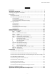
Raster Command Reference Contents Introduction ······························································································ 1 About Raster Commands ············································································ 2 1. Printing Using Raster Commands ····························································· 3 2. Print Data ······························································································ 5 2.
Raster Command Reference Introduction This material provides the necessary information for directly controlling the Brother printer QL-XXX (where “XXX” is the model name). This information is provided assuming that the user has full understanding of the operating system being used and basic mastery of USB and networks in a developer's environment. Details concerning the USB interface are not described in this material.
Raster Command Reference About Raster Commands Using raster commands a QL-XXX printer (where “XXX” is the model name) can be used to print without using our printer driver. This operation is useful in the following situations. ⚫ When printing from an operating system other than Windows (Example: When printing from a Linux computer or mobile terminal) ⚫ When adding print functions to an existing system In addition, printing can be performed with advanced settings.
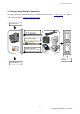
Raster Command Reference 1. Printing Using Raster Commands The printing procedure is described below. For detailed flow charts, refer to “5. Flow Charts”. For details on each command, refer to “4. Printing Command Details”. (1) Open the port Port (2) Receive the status (Confirm the printer status.) At your side (プリンタの状態を確認) (3) Send the print data (5) Receive the status (Confirm that printing is completed.) Computer, mobile terminal, etc. Your printer (4) Print (6) Close the port - 3 1.
Raster Command Reference (1) Open the USB/serial/network port Open the USB/serial/network port in the operating environment. The procedure for opening the USB/serial/network port is not described in this material. (2) Confirm the printer status sent from the printer The “status information request” command is sent to the printer, the status information received from the printer is analyzed, and then the status of the printer is determined.
Raster Command Reference 2. Print Data 2.1 Print data overview The print data is constructed of the following: (1) initialization commands, (2) control codes, (3) raster data, and (4) print commands. If the print job consists of multiple pages, (2) through (4) are repeated. (1) Initialization commands Specified only once at the beginning of the job. Sequence Command Name Description/Example 1 Invalidate Sends a 400-byte invalidate command, and then resets the printer to the receiving state.
Raster Command Reference mode To send the data compressed to TIFF format: 4Dh, 02h - 6 2.
Raster Command Reference (3) Raster data Repeated for each page in the print job. Sequence Command Name Description/Example - Raster graphics transfer Sends image data as commands. - Two-color raster graphics transfer Sends image data as commands for red-black printing. - Zero raster graphics Sends image data for 1 blank line as a compression command. (Valid only when TIFF is selected as the compression mode) 5Ah (Fixed) (4) Print commands Specified at the end of the page.
Raster Command Reference 2.2 Sample (analyzing the print data of the test page) Based on print data created by the printer driver, descriptions of the commands introduced in the previous chapter are provided here. As an example, we will check the print data created when the [Print Test Page] button in the printer Properties dialog box is clicked to print the test page.
Raster Command Reference Step 1: Change the port of the printer to “FILE:”. Open the Printers and Faxes folder, and then right-click the printer to display the Properties dialog box. In the Properties dialog box, click the [Ports] tab, select the “FILE:” check box, and then click the [Apply] button. [Ports] tab of the printer Properties dialog box Step 2: Print the item (in this case, the test page), and then specify the file name.
Raster Command Reference When the test page is printed with the printer, a dialog box appears so that the file name can be specified. (Refer to the illustration below.) After a file name is typed in and the [OK] button is clicked, the printer driver creates the print data and saves it in a file with the specified name. Dialog box for specifying the file name Step 3: Open the print data in the binary file editor. Open the saved file in the binary file editor.
Raster Command Reference 2.2.3 Explanation of print data for the test page The print data for the test page outputted in the previous section is described below. The following illustration shows the print data created in section “2.2.1 Preparation” opened in the binary file editor. 1 2 3 5 4 6 7 8 9 10 11 12 13 Print data - 11 2.
Raster Command Reference Descriptions for the numbers in the print data on the previous page are provided in the following table. For details on each command, refer to “4. Printing Command Details”. No. Command Name Description 1 Invalidate A 400-byte invalidate command is sent. 2 Initialize The “initialize” command is sent. 3 Switch dynamic command mode The printer is switched to raster mode. Send this command before sending raster data to the printer.
Raster Command Reference 2.3 Page data details 2.3.1 Resolution Resolution Height-to-Width Proportion 300 dpi high, 300 dpi wide 1:1 600 dpi high, 300 dpi wide 2:1 2.3.
Raster Command Reference 264 38mm 38 mm 1.4" 38.0 mm 449 dots →2.3.4 35.0 mm 413 dots →2.3.4 1.5 mm 18 dots →2.3.3 262 50 mm 50 mm 1.9" 50.0 mm 590 dots →2.3.4 46.9 mm 554 dots →2.3.4 1.5 mm 18 dots →2.3.3 261 54 mm 54 mm 2.1" 53.8 mm 636 dots →2.3.4 50.0 mm 590 dots →2.3.4 1.9 mm 23 dots →2.3.3 259 62 mm 62 mm 2.4" 62.0 mm 732 dots →2.3.4 58.9 mm 696 dots →2.3.4 1.5 mm 18 dots →2.3.3 - 14 2.
Raster Command Reference (b) Die-cut labels 1 1 5 3 5 3 6 6 8 Print area 10 2 2 4 4 Print area 7 Number ID 9 1 Width 2 Length 3 Print area width (maximum printing width) 4 Print area length 5 Width offset 6 Length offset 7 Width offset of masked area 8 Length offset of masked area 9 Width of masked area 10 Length of masked area Label Size 1 2 3 4 5 6 269 17 mm x 54 mm 0.66" x 2.1" 17.0 mm 201 dots 53.9 mm 636 dots 14.0 mm 165 dots 47.9 mm 566 dots 1.
Raster Command Reference 383 60 mm x 86 mm 2.3" x 3.4" 60.0 mm 708 dots 86.8 mm 1024 dots 56.9 mm 672 dots 80.8 mm 954 dots 1.5 mm 18 dots 3.0 mm 35 dots 274 62 mm x 29 mm 2.4" x 1.1" 62.0 mm 732 dots 28.9 mm 341 dots 58.9 mm 696 dots 22.9 mm 271 dots 1.5 mm 18 dots 3.0 mm 35 dots 388 62 mm x 60 mm 2.4" x 2.3" 62.0 mm 732 dots 60.6 mm 716 dots 58.9 mm 696 dots 54.6 mm 645 dots 1.5 mm 18 dots 3.0 mm 35 dots 389 62 mm x 75 mm 2.4" x 2.9" 62.0 mm 732 dots 75.4 mm 891 dots 58.
Raster Command Reference Continuous length tape 12.7 mm 150 dots 1000 mm 11811 dots Die-cut labels Fixed Fixed *1 The number of dots in the table is for 300 dpi; it is difference in the high-resolution mode. - 17 2.
Raster Command Reference 2.3.5 Raster line As shown below, the parts with data to be printed are converted with “raster graphics transfer”, and the parts with no data are converted with “zero raster graphics”. On the actual tape, margins (feed) are added specified with “various mode” at the beginning and the end.
Raster Command Reference Total number of pins: 720 pins Number of pins for right margin Raster line Left and right margins First byte Number of print area pins Total number of pins Print area Last byte 0 pin Number of pins for left margin Feeding direction Pins on print head Continuous length tape: Tape Size Number of Pins for Left Margin Number of Print Area Pins Number of Pins for Right Margin Number of Bytes for Raster Graphics Transfer 12 mm 585 106 29 90 29 mm 408 306 6 90 38 mm
Raster Command Reference 23mm x 23mm 442 236 42 90 29mm x 42mm 408 306 6 90 29mm x 90mm 408 306 6 90 38mm x 90mm 295 413 12 90 39mm x 48mm 289 425 6 90 52mm x 29mm 142 578 0 90 54mm x 29mm 59 602 59 90 60mm x 86mm 24 672 24 90 62mm x 29mm 12 696 12 90 62mm x 100mm 12 696 12 90 12mm Dia 513 94 113 90 24mm Dia 442 236 42 90 58mm Dia 51 618 51 90 - 20 2.
Raster Command Reference 3.
Raster Command Reference 4. Printing Command Details NULL Invalidate ASCII: NULL Hexadecimal: 00 Description ⚫ Skipped ⚫ If data transmission is to be stopped midway, send the “initialize” command after sending the “invalidate” command for the appropriate number of bytes to return to the receiving state, where the print buffer is cleared.
Raster Command Reference Number Offset Size Name Value/Reference 1 0 1 Print head mark Fixed at 80h 2 1 1 Size Fixed at 20h 3 2 1 Reserved Fixed at “B” (42h) 4 3 1 Series code Fixed at “4” (34h) 5 4 1 Model code QL-800 “8” (38h) QL-810W “9” (39h) QL-820NWB “A” (41h) 6 5 1 Reserved Fixed at “0” (30h) 7 6 1 Reserved Fixed at “0” (30h) 8 7 1 Reserved Fixed at “00h” 9 8 1 Error information 1 Refer to table (1) below.
Raster Command Reference (1) Error information 1 Flag Mask Definition Bit 0 01h “No media” error Bit 1 02h “End of media” error (only for die-cut labels) Bit 2 04h Cutter jam Bit 3 08h (Not used) Bit 4 10h Printer in use Bit 5 20h Printer turned off Bit 6 40h High-voltage adapter (not used) Bit 7 80h Fan motor error (not used) (2) Error information 2 Flag Mask Definition Bit 0 01h “Replace media” error Bit 1 02h “Expansion buffer full” error Bit 2 04h Communication err
Raster Command Reference (3) Media width and length The media width and length is described in millimeters. 0~255 (0 to FFh) (a) Continuous length tape * Media Width: The tape width is indicated in millimeters. * Media Length: Fixed at 00h Media Media Width Media Length 12 mm 12 0 29 mm 29 0 38 mm 38 0 50 mm 50 0 54 mm 54 0 62 mm 62 0 (b) Die-cut labels * Media Width: The width of the die-cut section is indicated. * Media Length: The length of the die-cut section is indicated.
Raster Command Reference (4) Media type Media Type Value Description No media 00h Used as print information when the media type is not indicated. Continuous length tape 4Ah Used for both paper and film. Die-cut labels 4Bh Used for both paper and film.
Raster Command Reference (6) Phase type and phase number If the phase number is not used, both are fixed at 00h. Phase State Phase Type Receiving state 00h Printing state 01h Receiving state Phase Value (Dec.) Higher Order Bytes Lower Order Bytes Waiting to receive 0 00h 00h Phase Value (Dec.) Higher Order Bytes Lower Order Bytes Printing 0 00h 00h Printing state ⚫ When the printer is turned on, it is in the receiving state.
Raster Command Reference ESC @ Initialize ASCII: ESC @ Hexadecimal: 1B 40 Description ⚫ Initializes mode settings. ⚫ Also used to cancel printing. ESC i d Specify margin amount (feed amount) ASCII: ESC Hexadecimal: 1B i d {n1} {n2} 69 64 {n1} {n2} Description ⚫ Specifies the amount of the margins. ⚫ Margin amount (dots)=n1+n2*256 ⚫ With die-cut labels, the margin amount at the ends of the printed area is 0.
Raster Command Reference ESC i a ASCII: Switch dynamic command mode ESC Hexadecimal: 1B i a {n1} 69 61 {n1} Parameters Definitions of {n}: 0: ESC/P mode (default) 1: Raster mode (Be sure to switch to this mode.) 3: P-touch Template mode Description ⚫ Dynamically switches between the printer's command modes. A printer that receives this command operates in the specified command mode until the printer is turned off. ⚫ The printer must be switched to raster mode before raster data is sent to it.
Raster Command Reference ESC i ! Switch automatic status notification mode ASCII: ESC Hexadecimal: 1B i ! {n1} 69 21 {n1} Parameters Definitions of {n1} 0:Notify. (default) 1:Do not notify. Description ⚫ Dynamically switches whether the automatic status notification is given during printing. A printer that receives this command operates in the specified command mode until the printer is turned off.
Raster Command Reference Z Zero raster graphics ASCII: Z Hexadecimal: 5A Description ⚫ Fills raster line with 0 data. * The QL-800 does not support this command. FF Print command ASCII: FF Hexadecimal: 0C Description ⚫ Used as a print command at the end of pages other than the last page when multiple pages are printed. Control-Z ASCII: Print command with feeding Control-Z Hexadecimal: 1A Description ⚫ Used as a print command at the end of the last page. - 31 4.
Raster Command Reference ESC i z Print information command ASCII: ESC Hexadecimal: 1B i z {n1} {n2} {n3} {n4} {n5} {n6} {n7} {n8} {n9} {n10} 69 7A {n1} {n2} {n3} {n4} {n5} {n6} {n7} {n8} {n9} {n10} Description ⚫ Specifies the print information.
Raster Command Reference M Select compression mode ASCII: M Hexadecimal: 4D {n} {n} Parameters Definitions of {n} 0 No-compression mode (Enabled) 1 Reserved (Disabled) 2 TIFF (Enabled) Description ⚫ Selects the compression mode. Data compression is available only for data in raster graphic transfer. * The QL-800 does not support the compression mode. [TIFF(Pack Bits)] ⚫ 1-byte units ⚫ If the same data is repeated, the number of data units and that 1 byte of data are specified.
Raster Command Reference Explanation of “TIFF compression mode” With compression, the data for the “raster graphics transfer” command is based on 90 bytes of the total number of pins (720). As shown below, with no compression, the sum of the number of offset pins and the number of pins within the print area is the byte data. However, with compression, the number of unused pins is also added to the data.
Raster Command Reference ESC i M Various mode ASCII: ESC Hexadecimal: 1B i M {n} 69 4D {n} Parameters Definitions of {n} The meaning of each bit in a 1-byte parameter is described below. 1 ~ 6bit: Not used 7bit: Auto cut 1: Auto cut 0:No auto cut 8bit: Not used ESC i K Expanded mode ASCII: ESC Hexadecimal: 1B i K {n} 69 4B {n} Parameters Definitions of {n} The meaning of each bit in a 1-byte parameter is described below.
Raster Command Reference 5. Flow Charts 5.1 Normal flow for USB connection Printer Computer (host) The printer is initialized. Initialize If there are no problems with the printer status (media, etc.), the data is READ transmitted. If there is a problem, an error appears. Displaying sending Status information request Status (response to status information request) The status of the printer (media, etc.) is checked and a response is sent. Data received.
Raster Command Reference 5.2 Error flow for USB connection (when feeding at the end of the page) Computer (host) Printer The printer is initialized. Initialize If there are no problems with the printer status (media, READ etc.), the data is transmitted. If there is a problem, an error appears. Displaying sending Status information request Status (response to status information request) Sending control codes The status of the printer (media, etc.) is checked and a response is sent. Data received.
Raster Command Reference 5.3 Error flow for USB connection (with a concurrent printing error such as end of tape) Computer (host) If there are no problems with the printer status (media, etc.), the data is transmitted. If there is a problem, an error appears. Printer Initialize The printer is initialized. Status information request READ Status (response to status information request) Displaying sending Any jobs with errors remaining in the printer are cleared.
Raster Command Reference 5.4 Cooling flow for USB connection Computer (host) Printer Any jobs with errors remaining in the printer are cleared. Initialize If there are no problems with the printer status (media, etc.), the READ data is transmitted. If there is a problem, an error appears. Displaying sending The printer is initialized. The status of the printer (media, etc.) is checked and a response is sent. Status information request Status (response to status information request) Data received.
Raster Command Reference 5.5 Flow for setting serial connection baud rate Computer (host) Printer Specify baud rate Printer waiting to recover from 3000 ms Sleep “Specify baud rate completed” status (normal status) Old baud rate New baud rate Status information request Status (response to status information request) * The request/response at the new baud rate are simply to verify that communication is possible and may be omitted. - 40 5.
Raster Command Reference 5.6 Normal flow for serial connection Computer (host) Printer Initialize If there are no problems with the printer status (media, READ etc.), the data is transmitted. If there is a problem, an error appears. Displaying sending Status information request Status (response to status information request) Sending control codes The printer is initialized. The status of the printer (media, etc.) is checked and a response is sent. Data received.
Raster Command Reference 5.7 Error flow for serial connection Computer (host) Printer Initialize If there are no problems with the printer status READ (media, etc.), the data is transmitted. If there is a problem, an error appears. Displaying sending Status information request Status (response to status information request) or an error is displayed Sending control codes The printer is Initialized. The status of the printer (media, etc.) is checked and a response is sent. Data received.
Raster Command Reference 5.8 Cleaning flow for serial connection Computer (host) Printer Initialize If there are no problems with the printer status READ (media, etc.), the data is transmitted. If there is a problem, an error appears. Displaying sending Status information request The printer is initialized. Status (response to status request) Status (response to status information request) Sending control codes Data received.
Raster Command Reference 5.9 Normal Flow for Network (Standard TCP/IP port) Connection *With a network connection, print data from the operating system’s port monitor is simply sent as is. When it prints 2 pages data Printer Computer (host) Divide print data into particular size, and send it.
Raster Command Reference Appendix A: USB Specifications USB specifications 1.
Raster Command Reference Appendix B: Introducing the Brother Developer Center Useful information for developers, such as applications, tools, SDKs as well as FAQs, are provided in the Brother Developer Center. http://www.brother.com/product/dev/index.