Software Developer's Manual Raster Command Reference RJ-4250WB/4230B/3230B/3250WB/3050/3150/ 2030/2050/2140/2150 Version 1.
The Brother logo is a registered trademark of Brother Industries, Ltd. Brother is a registered trademark of Brother Industries, Ltd. © 2014-2021 Brother Industries, Ltd. All rights reserved. Each owner whose software title is mentioned in this document has a Software License Agreement specific to its proprietary programs.
IMPORTANT - PLEASE READ CAREFULLY Note This documentation (“Documentation”) provides information that will assist you in controlling your Printer RJ-XXXX (where “XXXX” is the model name). You may use the Documentation only if you first agree to the following conditions. If you do not agree to the following conditions, you may not use the Documentation. Condition of Use You may use and reproduce the Documentation to the extent necessary for your own use of your Printer Model (“Purpose”).
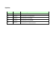
Updates Version Date Contents changed 1.00 7/11/2014 Initial version for RJ-3000 Series 1.01 10/4/2016 Add information of RJ-2000 Series 1.02 4/16/2018 Add information of RJ-4230B 1.03 8/27/2018 Add information of RJ-4250WB 1.
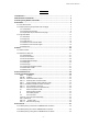
Raster Command Reference Contents 1. Introduction ··························································································· 1 2. About Raster Commands ········································································· 2 3. Printing Using Raster Commands ····························································· 3 4. Print Data ······························································································ 5 4.
Raster Command Reference 8.4 Buffered printing waiting for peeling/resumed flow for USB/Bluetooth connection······· 51 8.
Raster Command Reference 1. Introduction This material provides the necessary information for directly controlling the Brother printer RJ-XXXX (where “XXXX” is the model name). This information is provided assuming that the user has full understanding of the operating system being used and basic mastery of USB and networks in a developer's environment. Details concerning the USB interface are not described in this material.
Raster Command Reference 2. About Raster Commands Using raster commands an RJ-XXXX printer (where “XXXX” is the model name) can be used to print without using our printer driver. This operation is useful in the following situations. ⚫ When printing from an operating system other than Windows (Example: When printing from a Linux computer or mobile terminal) ⚫ When adding print functions to an existing system In addition, printing can be performed with advanced settings.
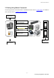
Raster Command Reference 3. Printing Using Raster Commands The printing procedure is described below. For detailed flow charts, refer to “8. Flow Charts”. For details on each command, refer to “7. Printing Command Details”. (1) Open the port Port (2) Send the status (Confirm the printer status.) At your side (プリンタの状態を確認) (3) Send the print data (5) Send the status (Confirm that printing is completed.) Computer, mobile terminal, etc. Your printer (4) Print (6) Close the port - 3 3.
Raster Command Reference (1) Open the USB/network port Open the USB/network port in the operating environment. The procedure for opening the USB/network port is not described in this material. (2) Confirm the printer status sent from the printer The “status information request” command is sent to the printer, the status information received from the printer is analyzed, and then the status of the printer is determined.
Raster Command Reference 4. Print Data 4.1 Print data overview The print data is constructed of the following: (1) initialization commands, (2) control codes, (3) raster data, and (4) print commands. If the print job consists of multiple pages, (2) through (4) are repeated. (1) Initialization commands Specified only once at the beginning of the job.
Raster Command Reference 7 Specify margin amount Specifies amount of margin. For 3 mm margin: 1Bh, 69h, 64h, 18h, 00h 8 Select compression mode Selects the compression mode for raster graphics. To send the data compressed to TIFF format: 4Dh, 02h - 6 4.
Raster Command Reference (3) Raster data Repeated for each page in the print job. Sequence Command Name Description/Example - Raster graphics transfer Sends a raster line that contains data with pixels set to “ON”. - Zero raster graphics Sends a raster line with all pixels set to “0”. 5Ah (Fixed) (4) Print commands Specified at the end of the page. Sequence Command Name Description/Example - Print command Specifies at the end of a page that is not the last page.
Raster Command Reference 4.2 Sample (analyzing the print data of the test page) The print data created by the printer driver is described here. As an example, we will check the print data created when the [Print Test Page] button in the printer Properties dialog box is clicked to print the test page. Since the print data differs depending on the print settings of the printer, refer to this procedure and try creating print data with various print settings.
Raster Command Reference 3: Open the path below in TreeView on the left-side of the Registry Editor. RJ-4250WB: \HKEY_LOCAL_MACHINE\SOFTWARE\Brother Industries, Ltd.\P-touch\Driver\3.0\Brother RJ-4250WB RJ-4230B: \HKEY_LOCAL_MACHINE\SOFTWARE\Brother Industries, Ltd.\P-touch\Driver\3.0\Brother RJ-4230B RJ-3250WB: \HKEY_LOCAL_MACHINE\SOFTWARE\Brother Industries, Ltd.\P-touch\Driver\3.0\Brother RJ-3250WB RJ-3230B: \HKEY_LOCAL_MACHINE\SOFTWARE\Brother Industries, Ltd.\P-touch\Driver\3.0\Brother RJ-3230B 4: R
Raster Command Reference Step 1: Change the port of the printer to “FILE:”. Open the [Devices and Printers] window, right-click the printer, and then display the printer’s Properties dialog box. Click the [Ports] tab in the printer’s Properties dialog box, select the “FILE:” check box, and then click the [Apply] button. [Ports] tab of the printer Properties dialog box Step 2: Print the item (in this case, the test page), and then specify the file name.
Raster Command Reference When the test page is printed with the printer, a dialog box appears so that the file name can be specified. (Refer to the illustration below.) After a file name is typed in and the [OK] button is clicked, the printer driver creates the print data and saves it in a file with the specified name. Dialog box for specifying the file name Step 3: Open the print data in the binary file editor. Open the saved file in the binary file editor.
Raster Command Reference 4.2.3 Explanation of print data for the test page The print data for the test page outputted in the previous section is described below. The following illustration shows the print data created in section “4.2.1 Preparation” opened in the binary file editor. Print data (Left: RJ-3000 and RJ-2000, Right: RJ-4200) - 12 4.
Raster Command Reference Descriptions for the numbers in the print data on the previous page are provided in the following table. For details on each command, refer to “7. Printing Command Details”. No. Command Name Description 1 Invalidate A 350-byte invalidate command is sent. (With the RJ-2000, a 200-byte invalidate command is sent.) 2 Initialize The “initialize” command is sent. 3 Switch dynamic command mode The printer is switched to raster mode.
Raster Command Reference 4.3 Page data details 4.3.1 Resolution Resolution Height-to-Width Proportion 203 dpi high, 203 dpi wide 1:1 4.3.2 Page size (a) Continuous length tape 1 5 3 6 Feeding direction 2 Print area 2 6 4 4 5 1 3 Print area Feeding direction Landscape Number Portrait 1 Width 2 Length 3 Print area width (maximum printing width) 4 Print area length 5 Width offset 6 Length offset RJ-2000 ID 442 426 Tape Size 1 RD 50 mm 50.0 mm RD 1.9" 400 dots RD 58 mm 58.
Raster Command Reference RJ-3050/3150 ID 442 426 439 441 Tape Size 1 RD 50 mm 50.0 mm RD 1.9" 400 dots RD 58 mm 58.0 mm RD 2.2" 464 dots RD 76 mm 76.2 mm RD 3.0" 610 dots RD 80 mm 80.0 mm RD 3.15" 640 dots 2 →4.3.4 →4.3.4 →4.3.4 →4.3.4 3 47.0 mm 376 dots 55.1 mm 440 dots 72.1 mm 576 dots 72.1 mm 576 dots 4 →4.3.5 →4.3.5 →4.3.5 →4.3.5 5 1.5 mm 12 dots 1.5 mm 12 dots 2.1 mm 17 dots 4.0 mm 32 dots 6 →4.3.3 →4.3.3 →4.3.3 →4.3.
Raster Command Reference (b) Die-cut labels 1 5 3 6 2 Number 4 Print area 1 Width 2 Length 3 Print area width (maximum printing width) 4 Print area length 5 Width offset 6 Length offset RJ-2000 ID 427 422 446 Label Size 1 2 3 4 5 6 RD 50 mm x 85 mm 50.0 mm 85.0 mm 47.0 mm 79.0 mm 1.5 mm 3.0 mm RD 1.9" x 3.3" 400 dots 679 dots 376 dots 632 dots 12 dots 24 dots RD 51 mm x 26 mm 50.8 mm 25.6 mm 47.8 mm 19.6 mm 1.5 mm 3.0 mm RD 2.0" x 1.
Raster Command Reference RJ-3230B/RJ-3250WB ID 447 427 446 428 443 Label Size 1 2 3 4 5 6 RD 50mm x 25mm 50.8 mm 25.6 mm 47.8 mm 19.6 mm 1.5 mm 3.0 mm RD 1.9" x 1" 406 dots 204 dots 382 dots 156 dots 12 dots 24 dots RD 50 mm x 85 mm 50.0 mm 85.0 mm 47.0 mm 79.0 mm 1.5 mm 3.0 mm RD 1.9" x 3.3" 400 dots 679 dots 376 dots 632 dots 12 dots 24 dots RD 55mm × 40mm 55.0 mm 40.0 mm 52.0 mm 34.0 mm 1.5 mm 3.0 mm RD 2.1" x 1.
Raster Command Reference 4.3.3 Feed amount The feed amount (left and right margins) is defined below. Type Minimum Margin Setting Maximum Margin Setting Continuous length tape 3.0 mm 0.12" 24 dots 127.0 mm 5" 1015 dots Die-cut labels The length offset indicated in “(b) Die-cut labels” of “4.3.2 Page size” is used. However, set “0” as the value of the “specify margin amount” command. - 18 4.
Raster Command Reference 4.3.4 Maximum and minimum widths The maximum and minimum printable widths are defined below. Type Minimum Width Maximum Width RJ-2000 RJ-3000/RJ-3200 RJ-4200 0.47" 58.0 mm 72.0.mm 104.1 mm 96dots 2.28" 2.83" 4.09" 432 dots 576 dots 832 dots Continuous length 12.0mm tape Die-cut labels 4.3.5 Maximum and minimum lengths The maximum and minimum printable lengths are defined below. Type Minimum Length Continuous length tape 12.0 mm 0.
Raster Command Reference 4.3.6 Raster line As shown below, the parts with data to be printed are converted with “raster graphics transfer”, and the parts with no data are converted with “zero raster graphics”. On the actual tape, margins (feed) are added specified with “various mode settings” at the beginning and the end.
Raster Command Reference RJ-2000 Total number of pins: 432 pins Number of pins for right margin Raster line Left and right margins First byte Number of print area pins Total number of pins Print area Last byte 0 pin Number of pins for left margin Feeding direction Pins on print head Continuous length tape: Number of Pins Number of Print Number of Pins for Number of Bytes for for Left Margin Area Pins Right Margin Raster Graphics Transfer 50 mm 25 382 25 54 58 mm 0 432 0 54 Number
Raster Command Reference RJ-3000/RJ-3200 Total number of pins: 576 pins Number of pins for right margin Raster line Left and right margins First byte Number of print area pins Total number of pins Print area Last byte 0 pin Number of pins for left margin Feeding direction Pins on print head Continuous length tape: Number of Pins Number of Print Number of Pins for Number of Bytes for for Left Margin Area Pins Right Margin Raster Graphics Transfer 50 mm(RJ-3000) 100 376 100 72 50 mm(RJ-3
Raster Command Reference Die-cut labels: RJ-3050/3150 Number of Pins Number of Print Number of Pins for Number of Bytes for for Left Margin Area Pins Right Margin Raster Graphics Transfer 50 mm x 85 mm 100 376 100 72 60 mm x 92 mm 60 456 60 72 76 mm x 44 mm 0 576 0 72 Label Size Die-cut labels RJ-3230B/RJ-3250WB Label Size Number of Pins for Left Margin Number of Print Area Pins Number of Pins Number of Bytes for for Right Margin Raster Graphics Transfer 50mm x 25mm 97 382
Raster Command Reference RJ-4200 Total number of pins: 832 pins Number of pins for right margin Raster line Left and right margins First byte Number of print area pins Total number of pins Print area Last byte 0 pin Number of pins for left margin Feeding direction Pins on print head Continuous length tape: Number of Pins Number of Print Number of Pins for Number of Bytes for for Left Margin Area Pins Right Margin Raster Graphics Transfer 50 mm 196 440 196 104 102 mm 22 788 22 104
Raster Command Reference 5. Status 5.1 Status overview The status is sent from the printer to the computer as a reply to the “status information request” command or as an error message. The size is fixed at 32 bytes. Number Offset Size Name Value/Reference 1 0 1 Print head mark Fixed at 80h 2 1 1 Size Fixed at 20h 3 2 1 Brother code Fixed at “B” (42h) 4 3 1 Series code Refer to 5.2.1 Series/model 5 4 1 Model code Refer to 5.2.
Raster Command Reference 24 23 1 Expansion area (number of bytes) Fixed at 00h 25 24 8 Reserved Fixed at 00h - 26 5.
Raster Command Reference 5.2 Definitions of each part 5.2.1 Series/model Status code Model name Series Model RJ-2030 “7” (37h) “6” (36h) RJ-2050 “7” (37h) “7” (37h) RJ-2140 “7” (37h) “8” (38h) RJ-2150 “7” (37h) “9” (39h) RJ-3050 “7” (37h) “3” (33h) RJ-3150 “7” (37h) “4” (34h) RJ-3230B “7” (37h) “E”(45h) RJ-3250WB “7” (37h) “F”(46h) RJ-4230B “7” (37h) “C” (43h) RJ-4250WB “7” (37h) “D” (44h) 5.2.
Raster Command Reference 5.2.3 Error information 2 Flag Mask Definition Bit 0 01h (Not used) Bit 1 02h “Expansion buffer full” error Bit 2 04h Communication error Bit 3 08h (Not used) Bit 4 10h “Cover open” error Bit 5 20h Overheating error Bit 6 40h Media cannot be fed (also when the media end is detected) Bit 7 80h (Not used) - 28 5.
Raster Command Reference 5.2.4 Media width and length The media width and length is described in millimeters. 0 ~ 255 (0 to FFh) (a) Continuous length tape * Media Width: The tape width is indicated in millimeters.
Raster Command Reference RJ-3000 / RJ-3200 Media Media Width Media Length 50mm x 25mm (RJ-3200) 32h 19h 50 mm x 85 mm 32h 55h 55mm × 40mm (RJ-3200) 37h 28h 60 mm x 92 mm 3Ch 5Ch 76 mm x 44 mm 4Ch 2Ch Media Media Width Media Length 50 mm x 85 mm 32h 55h 60 mm x 92 mm 3Ch 5Ch 80 mm x 115 mm 50h 73h 102 mm x 26 mm 66h 1Ah 102 mm x 50 mm 66h 32h 102 mm x 76 mm 66h 4Ch 102 mm x 102 mm 66h 66h 102 mm x 152 mm 66h 98h RJ-4200 5.2.
Raster Command Reference 5.2.6 Status type Status Type Value Reply to status request 00h Printing completed 01h Error occurred 02h Exit IF mode 03h(Not used) Turned off 04h Notification 05h Phase change 06h (Not used) 08h ~ 20h (Reserved) 21h ~ FFh 5.2.7 Phase type and phase number If the phase number is not used, both are fixed at 00h. Phase type Value Receiving state 00h Printing state 01h Receiving state Phase Value (Dec.
Raster Command Reference 5.2.8 Notification number Notification Value Not available 00h Cooling (started) 03h Cooling (finished) 04h Waiting for peeling 05h - 32 5.
Raster Command Reference 5.2.
Raster Command Reference 6.
Raster Command Reference 7. Printing Command Details NULL Invalidate ASCII: NULL Hexadecimal: 00 Description ⚫ Skipped ⚫ The specified number of bytes depending on the model will be sent. (RJ-4200 / RJ-3000 / RJ-3200: 350 bytes, RJ-2000: 200 bytes) ESC @ ASCII: Initialize ESC Hexadecimal: 1B @ 40 Description ⚫ Initializes mode settings. ⚫ Also used to cancel printing.
Raster Command Reference ESC i a ASCII: Switch dynamic command mode ESC Hexadecimal: 1B i a {n1} 69 61 {n1} Parameters Definitions of {n}: 0: ESC/P mode 1: Raster mode (Be sure to switch to this mode.) 3: P-touch Template mode (default) 4: CPCL Page Mode 5: CPCL Line Mode FF: Mode set as default Description ⚫ Dynamically switches between the printer's command modes. A printer that receives this command operates in the specified command mode until the printer is turned off.
Raster Command Reference ESC i U w ASCII: Additional media information command ESC Hexadecimal: 1B i U w 1 {d1...d127} 69 55 77 01 {d1...d127} Description ⚫ Updates the media information for the printer. ⚫ Send to the printer the commands outputted with the “Save Paper Size Commands” function of Paper Size Setup. Note If the media information is the same as when printing was last performed, it is unnecessary to send the additional media information command.
Raster Command Reference 2. Open the [Devices and Printers] window, right-click the printer, and then display the Printing Preferences dialog box. Click the [Paper Size Setup] button on the [Basic] tab to display the Paper Size Setup dialog box. (Refer to the illustration below.) Click [Save Paper Size Commands] from the [Option] button to display a dialog box for creating a file for saving the paper size commands, and then save them in a file with the specified name. 3.
Raster Command Reference ESC i z Print information command ASCII: ESC Hexadecimal: 1B i z {n1} {n2} {n3} {n4} {n5} {n6} {n7} {n8} {n9} {n10} 69 7A {n1} {n2} {n3} {n4} {n5} {n6} {n7} {n8} {n9} {n10} Description ⚫ Specifies the print information.
Raster Command Reference ESC i d Specify margin amount (feed amount) ASCII: ESC Hexadecimal: 1B i d {n1} {n2} 69 64 {n1} {n2} Description ⚫ Specifies the amount of the margins. ⚫ Margin amount (dots) = n1 + n2*256 ⚫ With die-cut labels, the margin amount at the ends of the printed area is 0. (a) Continuous length tape Paper Tape Print area Margin amount Cut line (b) Die-cut labels Paper Label Print area Margin amount (only “0” is available) Cut line - 40 7.
Raster Command Reference M Select compression mode ASCII: M Hexadecimal: 4D {n} {n} Parameters Definitions of {n} 0 No-compression mode (Enabled) 1 Reserved (Disabled) 2 TIFF (Enabled) Description ⚫ Selects the compression mode. Data compression is available only for data in raster graphic transfer. ⚫ Registry has to be added in order to use TIFF compression mode on RJ-4200. For details, refer to section 4.2.1 Preparation.
Raster Command Reference Continue for the remaining number of bytes for the uncompressed data. Even if 00h continues until the end, it cannot be omitted. - 42 7.
Raster Command Reference Explanation of “TIFF compression mode” With compression, the data for the “raster graphics transfer” command is based on 104bytes (RJ-4200), 72 bytes (RJ-3000/RJ3200) or 54 bytes (RJ-2000) of the total number of pins (RJ-4200: 832, RJ-3000: 576 and RJ-2000: 432). As shown below, with no compression, the sum of the number of offset pins and the number of pins within the print area is the byte data. However, with compression, the number of unused pins is also added to the data.
Raster Command Reference g Raster graphics transfer ASCII: g Hexadecimal: 67 {s} {n} {d1} ... {dn} {s} {n} {d1} ... {dn} Parameters {s} 00h {n} Number of bytes of raster data (d1 to dh) However, use the following value if no compression is specified as the compression mode. (RJ-4200: n = 104, RJ-3000/3200: n = 72, RJ-2000: n = 54) {d1~dn} Raster data. Z Zero raster graphics ASCII: Z Hexadecimal: 5A Description ⚫ Fills raster line with 0 data.
Raster Command Reference ESC i CAN Cancel RJ-4200 / RJ-3200: ASCII: ESC i Hexadecimal: 1B CAN 69 18 RJ-3000 / RJ-2000: ASCII: ESC @ Hexadecimal: 1B 40 Description ⚫ Cancel sending data while sending printing data. For no-compression mode, may cancel printing previous page depending on the cancel timing. ⚫ Printing will not be cancelled after receiving the “Control-Z Print command with feeding”. ⚫ Used to initialize mode settings for RJ-3000 and RJ-2000. For details, refer to “ESC @ Initialize”.
Raster Command Reference ESC i w Wait time after printing RJ-3200 only: ASCII: ESC i w [n1] Hexadecimal: 1B 69 77 {n1} ⚫ Waits for specified time after printing every page. ⚫ Specifies wait time in units of 0.1 [sec] (=100 [msec]). 00h: No wait / Nonstop printing enabled (default) 01h to FFh: Waits for 0.1[sec] to 25.5[sec] / Nonstop printing disabled - 46 7.
Raster Command Reference 8. Flow Charts RJ-XXXX printers perform as buffered printing. Buffered printing is a method that a print starts after one page of print data is received. . - 47 8.
Raster Command Reference 8.1 Buffered printing normal flow for USB/Bluetooth connection Computer (host) Printer Invalidate If there are no problems with the printer status (media, READ etc.), the data is transmitted. If there is a problem, an error appears. Displaying sending Initialize Status information request Status (response to status information request) Sending control codes Printer reset The printer is initialized. The status of the printer (media, etc.
Raster Command Reference 8.2 Buffered printing error flow for USB/Bluetooth connection Computer (host) Printer Invalidate Initialize If there are no problems with the printer status READ (media, etc.), the data is transmitted. If there is a problem, an error appears. Displaying sending Status information request Status (response to status information request) or error occurred Sending control codes Printer reset The printer is initialized. The status of the printer (media, etc.
Raster Command Reference 8.3 Buffered printing cooling flow for USB/Bluetooth connection Computer (host) If there are no problems with the printer status READ (media, etc.), the data is transmitted. If there is a problem, an error appears. Displaying sending Printer Invalidate Printer reset Initialize The printer is initialized. Status information request Status (response to status information request) Sending control codes The status of the printer (media, etc.
Raster Command Reference 8.4 Buffered printing waiting for peeling/resumed flow for USB/Bluetooth connection Computer (host) Printer Invalidate If there are no problems with the printer status (media, READ etc.), the data is transmitted. If there is a problem, an error appears. Displaying sending Initialize Status information request Status (response to status information request) Sending control codes The printer is reset. The printer is initialized. The status of the printer (media, etc.
Raster Command Reference 8.5 Buffered printing cancelling flow in USB/Bluetooth connection Computer (host) Printer Invalidate If there are no problems with the printer status (media, READ etc.), the data is transmitted. If there is a problem, an error appears Displaying sending Initialize Status information request Status (response to status information request) Sending control codes Printer reset The printer is initialized. The status of the printer (media, etc.
Raster Command Reference Appendix A: Introducing the Brother Developer Center Useful information for developers, such as applications, tools, SDKs as well as FAQs, are provided in the Brother Developer Center. http://www.brother.com/product/dev/index.