
Brochure


85
DesignandInstallationSuggestions
Browning Gripbelt
®
"V" Drives are primarily intended for the
transmission of power with relatively high speed driving units. Their
acceptance by industry covers a broad field of applications including
installations on a wide variety of different types of equipment, including
speed increasing drives, V-flat drives, quarter-turn drives, multiple
shaft drives and conveyors. Many such applications are regularly
being designed and installed using stock parts.
Experience has proven that most drive applications fall within the
range of the stock drives as covered by the Gripbelt Drive Selection
Tables and the Sheave and Belt specifications contained within this
catalog. For drives not falling within this category, it is necessary
to review and use the Gripbelt Drive Engineering Data. Unusual
applications should be referred to Application Engineering.
Regardless of whether drives consist of stock or special items there
are certain primary conditions to consider with respect to the design
of satisfactory drives. Those most commonly encountered are:
1. Drives should always be installed with provision for center
distance adjustment. This is essential, because an adjustment
is necessary after the belt has set and seated properly in the
groove of the sheave. If centers must be fixed, idlers should be
used.
2. If possible, centers should not exceed 3 times the sum of the
sheave diameters nor be less than the diameter of the large
sheave.
3. If possible, the arc of contact of the belt on the smaller sheave
should not be less than 120°.
4. Belt speeds with cast iron sheaves cannot exceed 6500 feet
per minute. Another type of drive is usually more desirable for
speeds under 1000 feet per minute.
5. Special or dynamic balance may need consideration for belts
speeds exceeding 5000 feet per minute.
6. Full consideration and allowance for overload capacity in drives
increases belt life and improves operation. Study the Overload
Service Factors in this section carefully.
7. Severe temperature can have a major effect on belt life. There
should be a full and free circulation of air around the drive.
All drives operating in explosive atmospheres should be well
grounded and use static conducting belts.
Watch these points particularly when installing drives:
1. Be sure that shafts are parallel and sheaves are in proper
alignment. Check after eight hours of operation.
2. Do not drive sheaves on or off shafts. Be sure shaft and keyway
are smooth and that bore and key are of correct size. Remove
burrs by dressing lightly with finishing file. Wipe shaft, key and
bore clean with oil. Tighten screws carefully. Recheck and re-
tighten after eight hours of operation.
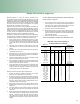
3. Belts should never be forced over sheaves. More belts are
broken from this cause than from actual failure in service. See
Table No. 1.
4. In mounting belts, be sure that the slack in each and every belt
is on the same side of the drive. This should be the slack side
of the drive.
5. Belt tension should be reasonable. When in operation the tight
side of belts should be in a straight line from sheave to sheave
and with a slight bow on the slack side. Check belt tension
after eight hours of operation. All drives should be inspected
periodically to be sure belts are under proper tension and not
slipping.
Formoredetailedtensioninginstructionsandaninexpensive
tensionchecker,seepage90.
6. Do not install new sets of belts in drives where the sheaves
have worn grooves. Such sheaves should be replaced with new
sheaves to insure a proper fit of the belts in the grooves, thus
help eliminate possibility of premature belt failure.
7. Keep belts clean. Do not use belt dressing.
8. When replacing belts on a drive, be sure to replace the entire
set with a new set of matched belts. Failure to do this will prob-
ably result in premature breakage of new (and probably shorter)
belts mixed with old ones.
9. Keep extra belts stored in a cool, dark, dry place.
Caution–Installguardsaccordingtolocalandnationalcodes.
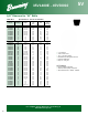
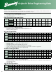
MinimumCenterDistanceAllowance
forBeltInstallationandTake-Up
Table No. 1
Allowance for
Allowance for Initial Tensioning
Belt No. Installation and Subsequent
Take-Up
A B C D All Sections
26 - 35 .8 1.0 – – 1.0
38 - 55 .8 1.0 1.5 – 1.5
60 - 85 .8 1.3 1.5 – 2.0
90 - 112 1.0 1.3 1.5 – 2.5
120 - 144 1.0 1.3 1.5 2.0 3.0
158 - 180 – 1.3 2.0 2.0 3.5
195 - 210 – 1.5 2.0 2.0 4.0
240 – 1.5 2.0 2.5 4.5
220 - 300 – 1.5 2.0 2.5 5.0
330 - 390 – – 2.0 2.5 6.0
420 and over – – 2.3 3.0 1
1
/
2
% of
Belt Length
3V 5V 8V All Sections
250 - 475 .5 – – 1.0
500 - 710 .8 1.0 – 1.2
750 - 1060 .8 1.0 1.5 1.5
1120 - 1250 .8 1.0 1.5 1.8
1320 - 1700 .8 1.0 1.5 2.2
1800 - 2000 – 1.0 1.8 2.5
2120 - 2240 – 1.2 1.8 2.8
2360 – 1.2 1.8 3.0
2500 - 2650 – 1.2 1.8 3.2
2800 - 3000 – 1.2 1.8 3.5
3150 – 1.2 1.8 4.0
3350 - 3550 – 1.5 2.0 4.0
3750 – – 2.0 4.5
4000 - 5000 – – 2.0 5.5
5600 – – 2.0 6.0
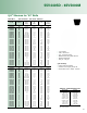
Belt No.
Allowance for
Installation (inches)
Allowance for
Initial Tensioning
and Subsequent
Take-Up (inches)
A B C D All Sections
26 - 35 0.8 1.0 – – 1
38 - 55 0.8 1.0 1.5 – 1.5
60 - 85 0.8 1.3 1.5 – 2
90 - 112 1 1.3 1.5 – 2.5
120 - 144 1 1.3 1.5 2.0 3
158 - 180 – 1.3 2.0 2.0 3.5
195 - 210 – 1.5 2.0 2.0 4
240 – 1.5 2.0 2.5 4.5
220 - 300 – 1.5 2.0 2.5 5
330 - 390 – – 2.0 2.5 6
420 and over – – 2.3 3
1 1/2% of
Belt Length
3V 5V 8V All Sections
250 - 475 0.5 – – 1.0
500 - 710 0.8 1 – 1.2
750 - 1060 0.8 1 1.5 1.5
1120 - 1250 0.8 1 1.5 1.8
1320 - 1700 0.8 1 1.5 2.2
1800 - 2000 – 1 1.8 2.5
2120 - 2240 – 1.2 1.8 2.8
2360 – 1.2 1.8 3
2500 - 2650 – 1.2 1.8 3.2
2800 - 3000 – 1.2 1.8 3.5
3150 – 1.2 1.8 4.0
3350 - 3550 – 1.5 2 4.0
3750 – – 2 4.5
4000 - 5000 – – 2 5.5
5600 – – 2 6.0