
Install Instructions
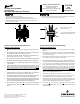

Single Groove Sheaves with Barrel Flats
Mounting and Adjusting:
1. Make sure the shaft, sheave bore and keyway are free of burrs, paint,
etc.
2. All sheaves should be mounted on the motor or driving shaft with the
end containing the setscrew “X” toward the motor.
3. Fit shaft key “D” between sheave and shaft, and lock setscrew “X” in
place. Wrench torque 110 in-lb min. - 130 in-lb max.
4. Be sure both driving and driven sheaves are in alignment and that shafts
are parallel. Total axial and parallel misalignment must not exceed 1/4°.
5. Loosen setscrew “Y” in movable ange of sheave until movable ange
is free to rotate.
6. Adjust sheave pitch diameter for desired speed by opening rotating
parts by half or full turn increments from closed position. Do not
open more than ve full turns for “A” belts or six full turns for “B” belts
(1VL34 or 1VP34, 5 turns). For other belt sections contact Application
Engineering for maximum full turns open.
7. Tighten setscrew “Y” to 110 to 130 in-lb. with set screw “Y” located over
center of cast ats on barrel of sheaves xed component.
8. Put on belts and adjust belt tension. (Do not force belts over grooves.)
A Browning
®
belt tension checker should be used to set tension.
9. Future adjustments should be made by loosening the belt tension and
increasing or decreasing the pitch diameter of the sheave by half or full
turns as required. Readjust belt tension before starting drive.
10. Be sure the key is in place and that all set screws are torqued properly
before starting drive. Check setscrews and belt tension after 24 hours
service.
F O R M
Variable Pitch VL/VM/VP
Type Sheaves
Mounting and Adjusting Instructions
3865
Revised
September 2010
Emerson Industrial Automation
7120 New Bufngton Road
Florence, KY 41042
Application Engineering: 800 626 2093
www.emerson-ept.com
• Periodic inspections should be performed. Failure to perform proper maintenance
can result in premature product failure and personal injury.
• Read and follow all instructions carefully.
• Disconnect and lock-out power before installation and maintenance.
Working on or near energized equipment can result in severe injury or death.
• Do not operate equipment without guards in place. Exposed equipment can
result in severe injury or death.
Browning Emerson, Emerson Industrial Automation are trademarks of
Emerson Electric Co. or one of its affiliated companies.
©2005, 2010 Emerson Power Transmission, All Rights Reserved.
MCIM10025 • Form 3865 • Printed in USA
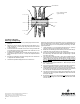
Single Groove Sheaves with Barrel Keys
Mounting and Adjusting:
1. Make sure the shaft, sheave bore, keys and keyways are free of burrs,
paint, etc.
2. All sheaves should be mounted on the motor or driving shaft with the
end containing the setscrew “X” toward the motor. Be sure setscrew
“X” is well over the shaft.
3. Fit shaft key “D” between sheave and shaft, and lock setscrew “X” in
place. Wrench torque 110 in-lb min. - 130 in-lb max.
4. Be sure both driving and driven sheaves are in alignment and that shafts
are parallel. Total axial and parallel misalignment must not exceed 1/4°.
5. Loosen set screw “Y” in movable flange of sheave and pull out external
key “E”. (This key projects a small amount to provide a grip for removing.)
6. Adjust sheave pitch diameter for desired speed by opening rotating
parts by half or full turn increments from closed position. Do not open
more than five full turns for “A” belts or six full turns for “B” or “5V” belts
(1VL34 or 1VP34, 5 turns). For other belt sections contact Application
Engineering for maximum full turns open.
7. Replace key “E” and tighten setscrew “Y” to 110 to 130 in-lb.
8. Put on belts and adjust belt tension. (Do not force belts over grooves.)
A Browning belt tension checker should be used to set tension.
9. Future adjustments should be made by loosening the belt tension and
increasing or decreasing the pitch diameter of the sheave by half or full
turns as required. Readjust belt tension before starting drive.
10. Be sure that all keys are in place and that all setscrews are torqued
properly before starting drive. Check setscrews and belt tension after
24 hours service.
X
Y
D
Y
E
D
X
Key“E” projects to provide
a grip for removing.
Do not operate sheave with flange
projecting beyond the hub end.