
Install Instructions

2
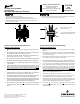
Two Groove Sheaves
Mounting and Adjusting:
1. Make sure the shaft, sheave bore, keys and keyways are free of burrs,
paint, etc.
2. Remove key “E” from sheave. Unscrew anges until setscrew “X” is
visible. If setscrew “X” is at an angle, ange may have to be removed
in order to tighten it.
3. All sheaves should be mounted on the motor or driving shaft with the
end containing the setscrew “X” toward the motor. If setscrew “X” is at
an angle, mount away from motor.
4. Fit shaft key “D” between sheave and shaft, and lock set screw “X” in
place. Wrench torque 110 in-lb min. - 130 in-lb max. Replace outboard
ange.
5. Be sure the center ange of both the driving and driven sheaves are
in alignment and shafts are parallel.
6. Total axial and parallel misalignment must not exceed 1/4°.
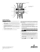
Each ange of the sheave has a small notch on the O.D. of the ange. This
mark is located directly over the keyway on the two adjustable anges and
over one of the keyways on the non-adjustable (center) ange. To obtain
proper adjustments:
7. Loosen setscrews “Y” in moving anges and pull out key “E”. (This key
projects a small amount to provide a grip for removing.)
8. Rotate both movable anges inward until they touch the center ange.
9. Locate the notch over the keyway on the center ange.
10. Open each movable ange until its notch is adjacent to the notch on
the center ange. Be certain that neither movable ange is opened
more than one full turn.
11. From the position obtained in Step 4, open each movable ange the
same number of full or half turns until the desired number of turns is
obtained. Do not open more than ve full turns for “A” belts or six full
turns for “B” belts. (2VP36 5 turns). For other belt sections contact
Application Engineering for maximum full turns open.
12. Replace key “E” and tighten setscrews “Y”. Wrench torque 110 in-lb
min. - 130 in-lb max.
13. Put on belts and adjust belt tension. (Do not force belts over anges.)
A Browning belt tension checker should be used to set tension.
14. Future adjustments should be made by loosening the belt tension and
increasing or decreasing the pitch diameter of the sheave by half or full
turns as required. Readjust belt tension before starting drive.
15. Two groove sheaves must have both halves adjusted by the same
number of turns from the position established in Step 4 to ensure the
same pitch diameter.
16. Be sure that all keys are in place and that all setscrews are torqued
properly before starting drive. Check setscrews and belt tension after
24 hours service.
Browning Emerson, Emerson Industrial Automation are trademarks of
Emerson Electric Co. or one of its affiliated companies.
©2005, 2010 Emerson Power Transmission, All Rights Reserved.
MCIM10025 • Form 3865 • Printed in USA
Y
X
Y
OD notched here.
E
D
Key“E” projects to provide
a grip for removing.