
User's Guide

BR-RC1190-Mod User Guide
92 Advance Rd. Toronto, ON. M8Z 2T7 Canada
Tel: 416 231 5535
www.broy.com
All configuration settings and RAM values are retained in sleep mode.
Interfaces
Power Supplies
Power is supplied through the VCC pin by applying 5V +-10%.
Module Reset
The module can be reset by driving the RESET pin low.
RF Antenna Interface
The BR-RC1190-Mod has been certified to be used with an external antenna (Linx p/n: ANT-916-CW-HD). The antenna connects to the
module through an RF connector.
Data Interfaces
The module features a 5V UART interface through the RXD and TXD pins. The UART interface can be used to configure the module.
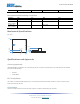
Pin Definition
Pinout
Pin Name Description
1 VCC Power pin, connect to 5V.
2 RXD UART interface (5V logic).
3 TXD UART interface (5V logic).
4 RESET Module reset (5V logic).
5 CONFIG Config pin (5V logic).
6-10, 15-22 NC Pins not connected on the module.
11-14, 23, 24 GND Connect to ground.
Electrical Specifications
Absolute Maximum Ratings
Pin Description Min Max Unit
VCC Module supply voltage -0.3 6.0 V
RXD, TXD UART interface -0.5 6.5 V