
Installation Guide


For Glue-Down Installations
• Recommended adhesive and adhesive remover
• 1/4˝ x 1/2˝ x 3/16˝ (6 mm x 13 mm x 8 mm) V-Notch
trowel (Figure 2) or other adhesive manufacturer’s
trowel
• 3M Scotch-Blue™ 2080 tape
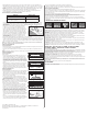
III. SUBFLOOR/UNDERLAYMENT
REQUIREMENTS
NOTE: Solid hardwood flooring can be fastened to most existing flooring materials providing they can be penetrated
with the fastener and the subfloor/underlayment materials meet or exceed the recommended subfloor/underlayment
requirements. Laminated rosin paper or 15# builders felt (tar paper) acts as a moisture retarder and may be used to
reduce movement caused by changes in subfloor moisture, thereby reducing cupping and warping. (This is especially
helpful over crawl spaces and basements.) In addition, the use of these materials can give the flooring a more solid
feeling, reduce sound transfer, prevent noise caused by minor irregularities and debris, and make it easier to slide the
hardwood together across the surface of the subfloor. Kraft paper may be used to make installation easier but DOES
NOT serve any other purpose.
Wood Subfloors and Underlayment
General: The wood subflooring materials should not exceed 12% moisture content. Using a reliable wood moisture
meter, measure the moisture content of both the subfloor and the hardwood flooring to determine proper moisture
content. The difference between the moisture content of the wood subfloor and the hardwood flooring should not
exceed 3% for strip and 2% for plank flooring. When installing parallel to the floor joists it may be necessary to stiffen
the subfloor system by installing an additional minimum of 3/8˝ (9.5 mm) approved wood underlayment. Applicable
standards and recommendations of the construction and materials industries must be met or exceeded.
NOTE: As a flooring manufacturer, we are unable to evaluate each engineered joist/subfloor system. Spacing and
spans, as well as their engineering methods are the responsibility of the builder, engineer, architect or consumer who is
better able to evaluate the expected result based on site-related conditions and performance. The general information
provided below describes common, non-engineered joist/subfloor systems. Engineered flooring joist/subfloor systems
may allow for wider joist spacing and thinner subflooring materials.
Wood Structural Panel Subfloors and Underlayment
(Non-engineered)
To act as a moisture barrier, structural panels/underlayment must be installed sealed side down. When used as a
subfloor, allow 1/8˝ (3 mm) expansion space between each panel. If spacing is inadequate, cut in with a circular saw.
Do not cut in expansion space on tongue and groove panels.
• Plywood: Should be minimum CDX grade (exposure 1) and meet US Voluntary Product Standard PS1-95
performance standard or Canadian performance standard CAN/CSA 0325-0-92. The preferred thickness is 3/4˝
(19 mm) as a subfloor [minimum 5/8˝ (16 mm)]. When using an underlayment panel a minimum 3/8˝ (9.5 mm)
thickness is recommended.
• Oriented Strand Board (OSB): Conforming to US Voluntary Product Standard PS2-92 or Canadian performance
standard CAN/CSA 0325-0-92 construction sheathing. Check the underside of the panel for codes. When used
as a subfloor, the panels must be tongue and groove, and installed sealed side down. Minimum thickness to be
23/32˝ (18 mm) thick when used as a subfloor or 3/8˝ (9.5 mm) as an underlayment. Some board manufacturers’
recommendations vary.
Solid Wood Subfloors
• Minimum 3/4˝ (19 mm) thick with a maximum width of 6˝ (15 cm) installed at a 45° angle to the floor joists.
• The subfloor must be Group 1 dense softwood (Pine, Larch, Douglas Fir etc) No. 2 common, kiln dried with all board
ends bearing on joists.
Concrete
(Requires Additional Subfloor)
NOTE: The use of a plywood subfloor when installing solid hardwood flooring over a concrete slab is highly
recommended. In a situation where you must direct glue to concrete, review the adhesive manufacturer’s
recommendation for proper application, proper adhesive and correct trowel notch and spread rate, as well as their
warranty coverage (some adhesive manufacturers have had substantial success with direct glue applications (no
plywood subfloor) using a variety of different adhesives and moisture retardant systems).
Concrete Moisture Tests
All concrete subfloors should be tested, and results documented, for moisture content. Visual checks may not be
reliable. Test several areas, especially near exterior walls and walls containing plumbing. Acceptable test methods for
subfloor moisture content include:
• Tramex Concrete Moisture Encounter Meter (Figure 3): Moisture
readings should not exceed 4.5 on the upper scale. (Figure 3 shows
an unacceptable reading of over 4.5) Concrete Moisture Meters give
qualitative reading results-not quantitative ones. These results are a
quick way to determine if further testing is required.
NOTE: To ensure appropriate moisture content, the following tests
should be conducted in all residential/commercial applications.
(Either or both tests is/are acceptable).
• Calcium Chloride Test (ASTM F 1869): The maximum moisture
transfer must not exceed 3 lbs./1000 ft.
2
in 24 hrs. With this test.
• RH Levels in Concrete Using In-situ Probes (ASTM F 2170) should
not exceed 75%.
“DRY” CONCRETE, AS DEFINED BY THESE TESTS CAN BE WET AT OTHER TIMES OF THE YEAR. THESE TESTS DO
NOT GUARANTEE A DRY SLAB.
• Moisture Retardant System: If excessive moisture is present or anticipated, use a Moisture Retardant System.
Bruce
®
Summit Select™ All In One Premium Adhesive may be used as a moisture retardant system to reduce
vapor intrusion. Apply the adhesive using the Bruce Summit trowel that is included in every pail or other adhesive
manufacturer’s trowel. Flooring can be installed immediately after applying the adhesive. No moisture test is required.
Wood/Concrete Subfloor Systems
• Fastened to concrete: Install a suitable moisture retardant followed by a plywood subfloor with a minimum of 3/8˝
(9.5mm) [1/2˝ (13 mm) preferred]. Allow 1/2˝ (13 mm) expansion space around all vertical objects and 1/8˝ (3 mm)
between all flooring panels. Install a second layer of plywood, the same thickness, at a right angle to the previous
panels, offsetting the joints 2´ (61 cm). Staple together with staples that will not penetrate the first layer of the
subfloor. The staples should have a crown width of 3/8˝ (9.5 mm) or more. Install a moisture retardant barrier with
joints lapped 6˝ (15 cm) and begin installation of flooring using 1-1/2˝ (4 cm) fasteners.
• Screeds/sleepers: NOTE: Solid hardwood flooring 4˝ (10 cm) or more in width cannot be installed directly to
screeds. Screeds should be installed 9˝ (23 cm) apart, in rivers of adhesive, at right angles to the flooring to be
installed. Do not begin installation until all adhesives are properly cured. Install moisture retardant over the screeds
prior to installation of the flooring.
IV. INSTALLING THE FLOOR
General Installation Tips
• Install the moisture retardant (if used) parallel to the flooring. Overlap
the rows 6˝ (15 cm). Overlap (top) should be on the same side as the
groove of the flooring so that the hardwood will slide smoothly into
place. Staple the moisture retardant material as necessary to prevent
excessive movement.
• Use pieces of flooring from several different cartons at the same time
to ensure good color and shade mixture and variation.
• When possible, preselect and set aside boards that blend best with all
floor mounted moldings to ensure a uniform final appearance. Install
these boards adjoining the moldings.
2
• Be attentive to staggering the ends of boards at least 4˝-6˝ (10-15 cm), when possible, in adjacent rows (Figure 4).
This staggering pattern will help ensure a more favorable overall appearance of the floor.
• When installing products of uniform length, begin the rows with starter boards cut to various lengths. Avoid
staggering the rows uniformly to prevent stair-stepping. Boards cut from the opposite end of the row may be used for
the next starter boards.
• Large spans exceeding 20´ (6 m) in hardwood flooring width, in areas of high humidity, may require the addition
of internal or field expansion. This expansion can be accomplished by using spacers, such as small washers, every
10-20 rows inserted above the tongue. Remove the spacers after several adjoining rows have been fastened. Do not
leave spacers in for more than two hours.
• Always allow a minimum 3/4˝ (19 mm) expansion around all vertical obstructions.
• Always use a protective foot on the fastening machine to prevent mallet damage and edge bruising.
General Information for “Blind Fastening” Machines
• Avoid striking the edge of prefinished products with the fastener’s
mallet, as Edge crushing can occur, causing unsightly cracks and
splinters. Use a protective foot attachment to prevent edge bruising and
finish damage.
• Improper adapter plates and air pressure settings can cause severe
damage to the hardwood flooring and reduce performance (Figure 5).
Always use an in-line regulator to control air pressure to the machine.
Set pressure at 70-75 PSI to begin with and adjust until proper fastener
setting occurs.
NOTE: SPECIAL INSTRUCTIONS FOR PLANK FLOORING
Seasonal distortion (shrinkage/cupping) in wide width flooring (4˝ (10
cm) and over) may be reduced by gluing the flooring to the subfloor,
in addition to the use of mechanical fasteners. Reminder: adhesives
used for this purpose will not perform their function when used in
conjunction with a moisture retardant. Glue assisted applications will
not be satisfactory without direct contact with the subfloor. The glue
should be a premium grade urethane construction adhesive applied in a
serpentine pattern to the back of the hardwood plank in a 1/4˝ bead as
noted in Figure 6.
STEP 1: Doorway and Wall Preparation
(All Installations)
• Undercut door casings and jambs. Remove any existing base, shoe
mold or doorway thresholds. These items can be replaced after
installation. All door casings and jambs should be undercut to avoid
difficult scribe cuts (Figure 7).
STEP 2: Establish a Starting Point
(All Installations)
• For best visual results, install flooring parallel to the longest wall;
however, the floor should always be installed perpendicular to the
flooring joists unless subfloor has been reinforced to reduce subfloor
sagging.
• When possible, begin layout or installation from the straightest wall
(generally an outside wall).
• In at least two places at least 18˝ (46 cm) from the corner, measure
out equal distance from the starting wall (Figure 8) the face width of
the starter board plus 1˝ (2.5 cm) (do not include the width of the
tongue in this measurement). Mark these points and snap a chalk line
through them. This measurement allows for the required 3/4˝ (19 mm)
expansion and the width of the tongue.
STEP 3: Installing First & Second Rows – Starting from Wall
(Mechanically Fastened/Staple-Down Installations)
• Use the longest, straightest boards available for the first two rows.
For random and alternate width products, use the widest plank for the
first row. Align tongue of first row on chalk line. The groove should be
facing the starting wall.
• Use a pneumatic finish nailer to face-nail the groove side 1/2˝ (13 mm)
from the edge at 6˝ (15 cm) intervals and 1˝-3˝ (2.5-7.6 cm) from
each end. Then, blind nail using a finishing gun held at a 45° angle.
Nail down through the nailing “pocket” on top of the tongue every 6˝-8˝
(15-20 cm) (Figure 9).
• If using finish nails, pre-drill the nail holes with a 1/32˝ (1.7 mm) bit approximately 1/2˝ (12.7 mm) from back
(groove) edge, 1˝-3˝ (2.5-7.6 cm) from each end, and at 6˝ (15 cm) intervals. Pre-drill at the same intervals at a 45°
angle down through the nailing “pocket” on top of the tongue (Figure 9). Face-nail the groove side where pre-drilled.
When complete, blind-nail at a 45° angle through the tongue of the first row. Fasten using 6 or 8d finish nails.
Countersink nails to ensure flush engagement of the groove. Avoid bruising the hardwood by using a nail set to
countersink the nails.
• Continue blind-nailing using this method with the following rows until blind nailer can be used.
STEP 2- 3 Alternative: Installing First & Second Rows – Starting from Center of Room
(Mechanically Fastened/Staple-Down Installations)
• Snap a chalk line down the center of the room.
• Install a “sacrificial row” that extends the entire length of the room on the centerline.
• Install three rows of flooring.
• Remove the sacrificial row and insert wood glue in the groove followed by a slip tongue (spline) in the exposed
groove. Always glue and nail the slip tongue in place. Installation can now continue from the center in both directions.
NOTE: Do not reuse/reinstall the boards from the sacrificial row.
STEP 4: Dry Lay (Racking) the Floor
• “Dry” lay (rack) materials to cover approximately 2/3 of the room. Begin dry laying (racking) approximately 6˝ (15
cm) from the edge of the previously installed rows. Avoid pulling boards too tightly together on the sides, as they
must move freely when fastening begins.
• Do not cut final board until row has been installed. Cutting the board in advance may result in a board that is too
short.
• Visually inspect flooring, setting aside boards that need to have natural character flaws cut out. Use these boards for
the starting and finishing rows only after objectionable characteristics have been removed.
Fastener Schedule
Width of flooring
1-1/2˝ to 3-1/2˝ (4-9 cm) 4˝ (10 cm) and over
Maximum spacing 10˝-12˝ (25-30 cm) 8˝-10˝ (20-25 cm)
Preferred spacing 8˝-10˝ (20-25 cm) 6˝-8˝ (15-20 cm)
Figure 10
STEP 5: Installing the Floor
• Use the blind nailer to fasten a sacrificial board to the floor. Check for surface damage, air pressure setting,
tongue damage, before proceeding. Make all adjustments and corrections before installation begins. Once proper
adjustments have been made, remove and destroy the board.
Figure 2
Figure 3
Figure 4
Preferred Alignment
Too Low Too High Correct
Figure 5
Figure 6
Figure 7
Figure 8
Figure 9
chalk line
1st row 1st row
2nd row
face nail every
6˝ (15 cm)
blind nail into
tongue every
6˝-8˝ (15-20 cm)
tongue