Duo Installation Instructions & Reference Guide
Table of Contents OVERVIEW ............................................................................................................................................. 1 POWER REQUIREMENTS ........................................................................................................................ 2 FCC DECLARATION OF CONFORMITY ..................................................................................................... 3 CHAPTER 1: HANG THE DISPLAYS ....................................
Creating your own NAS disk ......................................................................................................... 67 3. NETWORKING COMPUTERS .............................................................................................................. 68 Naming Conventions .................................................................................................................... 68 Setting IP Addresses ..............................................................................
Fixed IP Address .......................................................................................................................... 94 VIEWING THE SCORING LOG................................................................................................................. 94 Saving the System Log ................................................................................................................. 94 Reboot and run Check Disk ................................................................
2YHUYLHZ Thank you for purchasing the Duo Automatic Scoring system. The Duo hardware should be able to be easily installed by a team of two or three people with a reasonable degree of technical competence. The Duo system consists of three parts: 1. The Duo CPU Module, which is responsible for all communications to the front counter as well as displaying the scoregrids and exciter animations. 2.
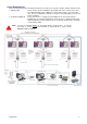
Power Requirements There are at least two power circuits that need to be present for the system to function (Shown in Pink, below): 1. Display Units. There must be a power available to the display units in the ceiling. There must be a GPO (General Purpose Outlet) for each monitor and also one for the Duo unit. There is a maximum of 8 lanes per circuit or lower, depending on your local power regulations. 2. Computer Equipment.
FCC Declaration of Conformity PRODUCT NAME: Duo MODEL NUMBER: FCC RULES: TESTED TO COMPLY WITH FCC PART 15, CLASS B OPERATING ENVIRONMENT STATEMENT: COMMERCIAL USE FCC COMPLIANCE STATEMENT: This device complies with part 15 of the FCC Rules. Operation is subject to the following two conditions: (1) This device may not cause harmful interference, and (2) this device must accept any interference received, including interference that may cause undesired operation.
&KDSWHU+DQJWKH’LVSOD\V The Duo system can be used with any type of display that can accept both a VGA and a DVI signal. This will often involve a TV that is either a Glass CRT (Cathode Ray Tube) or more commonly a TV that uses a LCD (Liquid Crystal Display) panel. Either way, you must also purchase and arrange for these displays to be hung from the ceiling.
Option2: Purchase your own displays. There are a number of manufacturers of mounting brackets for TVs and other displays that can be readily seen in Bars, Clubs and other facilities. This is a large industry, which should have a number of local suppliers who can advise you on the various methods on mounting displays onto the ceiling. Following are the web site addresses of some, but not all, of the major manufacturers of this type of equipment: www.atdec.com www.pivotelli.com www.peerlessindustries.
Connectors The image below is from a Samsung 400PX commercial display. It represents a very good display with all the connectors that you would need to correctly run the Duo, utilising all its features, with the minimum of complications. Below is a summary of the connectors used: (Like most TVs, there are some connectors that are not used.) VGA Input Plug in the Odd Lane Video output from the Duo CPU module into here, if the monitor is on the Odd Lane.
&KDSWHU5XQWKH&DEOHV There are three different methods to communicate to the Pinsetters. The manufacturer and model of the Pinsetter installed at your Bowling Center dictate which method is used and how the system is cabled: Type A This type uses the Duo Camera Module’s Machine Connection port for each machine in the pair. Machine connection relies on relays to open and close a switch contact, which is then wired into the Pinsetter’s control box to perform the required function.
Common Cables Although the cable that connects to each type of pinspotter is different, there are several cables that are used for some or all of the different classes of system. LLAN Communications Backbone The LLAN cable is used in Type A, Type B and Type C systems. The LLAN is the main communications backbone between all components of the Duo system. The LLAN cable can be of varying lengths in different situations. However, the wiring of this cable is always the same.
DCC IP Score Camera Cable The DCC cable is used in Type A and Type B systems. It is not used in Type C Systems. The DCC cable is used to carry signal from the Duo CPU module to the IP Camera at the Duo Camera module. This signal is in the form of a network connection, which is shielded to help protect from interference. The Duo Camera Module is not present in Type C systems, so the DCC and DUP cables are not used in this situation.
Optional Network Cable (DNC) The DNC cable is used in Type A, Type B and Type C systems. The Duo system is designed to have a stand alone basic scoring functionality, without the need to connect any computers at all. However, if you wish to control the lanes from a computer on the front counter, you will need to connect the Network Cable. (DNC) This cable is shown here in Blue.
Alternatively, a single switch can be used, however in this case all network cables must be run to that position. The advantage of this is that the networking is simpler and more efficient. It is for this reason that this method is the one recommended by Computer Score. The disadvantage is that there is more work involved in running the cables.
Type A Systems For each pair of lanes in a standard Type A installation there are five communications cables: 1. LLAN This cable runs from the Duo CPU module to the Duo Camera module. Another LLAN cable is then run from the Duo Camera module to the optional wired connection for the Bowler’s Keypad. This cable supplies both power and communications. 2. DCC This cable runs from the Duo CPU module to the Duo Camera module. This cable supplies video signal from the camera. 3.
Machine Connection Cable (DMO & DME) Brunswick A & A2 as well as AMF 82-30 & 82-70 Pinsetters are only capable accepting the basic on / off and cycle commands whereas all other later Pinsetter types are capable of accepting advanced commands such as 7 - 10 pick off, strike cycles and short cycles. The following Pinsetters use the Machine Connection port on the Duo Camera Module where as others use the Machine Communications port as discussed in the next section.
Chapter 2: Run the Cables – Type A 14
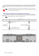
AMF 82-30 Run both the DMO-30 (Odd Lane) and DME-30 (Even Lane) cables from the Duo Camera Module, along the Ball Track, and up the kickback to the Odd and Even lane Pinsetter respectively. The Start cable is wired to the “P” Box at the front of the machine and the cycle cable is wired to the “J” Box. Again, the start contact is wired in series to the managers control switch and the cycle contact is wired in parallel to the cycle button from the ball return.
Chapter 2: Run the Cables – Type A 16
Chapter 2: Run the Cables – Type A 17
AMF 82-70 Run both the DMO-70 (Odd Lane) and DME-70 (Even Lane) cables from the Duo Camera Module, along the Ball Track, up the kickback, to the A&MC box located on the curtain wall, which is the common connection box for both lanes. Again, the start contact is wired in series to the managers control switch on AMC Pin 5 and the cycle contact is wired in parallel across AMC pins 1 & 2 to the cycle button from the ball return. The Foul signal is also wired to the AMC box across AMC pins 7 & 8.
Chapter 2: Run the Cables – Type A 19
AMF 82-70 with MP Chassis Run both the DMO-70MP (Odd Lane) and DME-70MP (Even Lane) cables from the Duo Camera Module, along the Ball Track, up the kickback. The DMO and DME cables each consist of two cables: A. One cable is then run to the A&MC box located on the curtain wall. Again, the start contact is wired in series to the managers control switch on AMC Pin 5. B. The other is run to the MP chassis.
Chapter 2: Run the Cables – Type A 21
AMF 82-70 with MK Expander Run both the DMO-70MK and DME-70MK cables from the Duo Camera Module, along the Ball Track, up the kickback. The DMO & DME cables each consist of three separate cables: A. The First cable is run to the A&MC box located on the curtain wall. Again, the start contact is wired in series to the managers control switch on AMC Pin 5 and the cycle contact is wired in parallel across AMC pins 1 & 2 to the cycle button from the ball return.
Chapter 2: Run the Cables – Type A 23
AMF 82-70 with XOP Chassis Run both the DMO-70XOP and DME-70XOP cables from the Duo Camera Module, along the Ball Track, up the kickback, to a location near the A&MC Box. The DMO & DME cables then each consist of three separate cables: A. The First cable is run to the A&MC box located on the curtain wall. Again, the start contact is wired in series to the managers control switch on AMC Pin 5 and the cycle contact is wired in parallel across AMC pins 1 & 2 to the cycle button from the ball return.
Chapter 2: Run the Cables – Type A 25
AMF 82-90 (Large Chassis) As the AMF 82-90 machine uses the same common chassis to control both the Odd and Even machines, the Duo Camera module only uses one cable to connect to this model of Pinsetter. Run the DM-90 cable from the Duo Hardware Module, along the Ball Track, up the kickback, to the 82-90 chassis at the rear of the Pinsetter, and plug into the APS connection at the back of the chassis. The DM-90 cable gives the Duo Camera Module signals for Cycle, Foul, Rake Down and Pinsetter Status.
Chapter 2: Run the Cables – Type A 27
Xima Pinsetter Run both the DMO-XM (Odd Lane) and DME-XM (Even Lane) cables from the Duo Camera Module, along the Ball Track, up the kickback, and then up to the Control box on the Odd and Even lanes respectively. Make sure you route all cables away from moving parts, so there is no chance of the cables being crushed or cut. The start contacts are connected in series to the managers control switch and the cycle contact is wired in parallel to the cycle button from the ball return.
Chapter 2: Run the Cables – Type A 29
VIA Pinsetter Run both the DMO-VIA (Odd Lane) and DME-VIA (Even Lane) cables from the Duo Camera Module, along the Ball Track, up the kickback, and then up to the cable tray at the front of the Odd and Even lanes respectively. Make sure you route all cables away from moving parts, so there is no chance of the cables being crushed or cut. All connections go to a single 15 pin plug on the MC2 Scoring Interface board, located in the cable tray.
Chapter 2: Run the Cables – Type A 31
Type B Systems For each pair of lanes in a standard Type B installation there are four communications cables: 1. LLAN This cable runs from the Duo CPU module to the Duo Camera module. Another LLAN cable is then run from the Duo Camera module to the optional wired connection for the Bowler’s Keypad. This cable supplies both power and communications. 2. DCC This cable runs from the Duo CPU module to the Duo Camera module. This cable supplies power and video signal to the camera. 3.
Machine Communications Cable (DXL) This cable will allow the Duo Camera unit to communicate with advanced Pinsetters such as the AMF 8800Gold, AMF 82-90XL and 90XLi. These machines allow the Duo to communicate with them at a software level. The Duo determines the score via the Camera and then tells the Pinsetter the score so that it can behave appropriately (Strike Cycle, 7 – 10 pickoff etc.
Chapter 2: Run the Cables – Type B 34
Type C Systems Type C systems refer to Brunswick GS Series Pinsetters which communicate directly to the Duo CPU module to tell the Duo the score, without the need for a Duo Camera Module at all. For each pair of lanes in a standard Type C installation there are three communications cables: 1. LLAN This cable runs from the Duo CPU module to the Duo LLAN Hub. Another LLAN cable is then run from the LLAN Hub to the optional wired connection for the Bowler’s Keypad. 2.
Brunswick GS-X (DGX) or Late Model GS-98 Route the DGX cable from the Duo Hub, under the capping, up the kickbacks to the GS-X Next Gen Box or GS-98 Consolidated Box control chassis.
Brunswick GS-10 / 96 / 98 with Pinsetter Interface Controller fitted (DG9). Route the DG9 cable from the Duo Hub, under the capping, up the kickbacks to the Pinsetter Interface Controller. The plug required is located inside the Pinsetter Interface Controller. Make sure you power off and disconnect BEFORE opening this box. Thread the cable through the existing stain relief clamp before connecting the 5-way connector into the J4 plug.
&KDSWHU 0RXQWWKH%RZOHU¶V.H\SDGFRQVROH The Bowler’s Keypad console must be secured to the floor very tightly, as this unit often must adsorb a large amount of abuse from the public. Even when properly secured, it is necessary to periodically check to make sure that all fittings are still tight. Vandals will exploit any looseness or slack and may result in damage to the pedestal base or the floor itself.
&KDSWHU6HFXUHWKHFDSSLQJ Perform this step ONLY if you use Type A or B connections to your Pinsetters. Skip this step if you use a Type C connection (Brunswick GS series) In order for the Duo system to consistently take accurate scores, the Camera Module MUST be securely attached to the lanes with no movement. For installation simplicity, the Duo Camera Module is designed to be screwed directly to the capping.
Note: Horizontal Bumpers. The only exception to the above steps is in the situation where swing out type bumpers has been previously installed. In this case, there is usually a gap between the existing bumper rails, at the position of the camera. A section of capping must be removed and packing timber must be secured to the sub timbers to allow the Duo Camera unit to be mounted at the correct height.
&KDSWHU$FFRXQWLQJIRU%XPSHU5DLOV Perform this step ONLY if you use Type A or B connections to your Pinsetters and you have bumper rails fitted. Skip this step if you use a Type C connection (Brunswick GS series) The Duo system relies on the ability to detect that a ball has gone past in order to start the scoring software routine. However, bumper rails can interfere with this because, if the Duo Camera unit is positioned incorrectly, the rail can cut the beam when it is raised or extended.
Vertical Bumpers and Ball Wall Bumper systems such as Brunswick’s Ball Wall & Pinball Wizard and AMF’s Duralane raise the bumper rail up from the gutter (or tilt the whole gutter in the case of Ball Wall). Therefore it is important that the Duo Camera Module be high enough so that the raised bumper rail does not cut the beam from the Ball Detector.
&KDSWHU,QVWDOOWKH’XR&DPHUD0RGXOH Perform this step ONLY if you use Type A or B connections to your Pinsetters. Skip this step if you use a Type C connection (Brunswick GS series) Secure to the Capping AMF and Brunswick Wooden and Plastic Capping Make sure that the Duo Unit is straight on the capping and in the middle. Then mount the Duo Units directly to the capping, using long screws to go right through the capping and bite into the sub timbers as well.
Mount the Reflectors Screw down the reflectors of the ball detectors on the intermediate (Thin) capping. Make sure that the reflectors are all in line and level with the ball detectors on the Duo Camera Modules. Mount Optional Camera Protector Incorrectly bowled balls, delivered by deliberately bowling down the capping between raised bumpers, can impact the Duo Camera unit and result in damage. Secure the Option Camera Protection Steelwork to the sub timbers, in front of the nearest join in the capping.
&KDSWHU3OXJ,QDQG3RZHU2Q The final step in installing the lane hardware is to plug in all the cables, power on the system and align the ball detectors. At the Duo CPU Module Plug in all your cables into their corresponding connectors on the Duo CPU Module as shown below: At the Duo Camera Module For Type A and Type B systems, install the various cables at both ends of the line as shown below. Type C systems do not require this step, as the Duo Camera Module is not present.
At the Bowler’s Keypad The Duo system has the option to communicate with the bowler’s keypads either via a wireless interface, or alternatively via an extension of the LLAN wired communications cable. Also, you have the option of either one or two keypads per lane pair. Depending on whether these options, you must set the following settings on the PC Board inside the keypad. This will tell the Keypad PCB Board how to behave when a key is pressed.
Dual Wired Keypads Remove the battery pack connector and plug in the LLAN cable from the Duo CPU Module into the LLAN IN connector on the Keyboard PCB (Printed Circuit Board) of the Odd Lane. Then, run a short LLAN cable from the LLAN OUT of the Odd Lane, through the steel keypad stand to the LLAN IN of the Even Lane’s keypad. Then you must set the Channel Number on the Rotary DIP Switches to: 01 for the Odd Lane. (Zero on the 10’s switch and One on the 1’s switch) and 02 for the Even Lane.
Wireless Keypads The advantage of wireless keypads is they allow you to have greater flexibility as to where they are located, they are also advantageous in situations where there is no cable conduit to the bowler’s score table. However you will occasionally need to change the batteries in order for them to continue to operate. For all wireless keypads, either single or dual, you must first verify that the jumper for JP2 and JP3 are set to the RIGHT.
Dual Wireless Keypads If you have dual keypads that will be used to wirelessly control one lane per keypad, then you must first set the following channel numbers: Odd Lane: Set the Channel Number on both the Rotary DIP switches to 10 (One on the 10’s switch and Zero on the 1’s switch) Even Lane: Set the Channel Number on both the Rotary DIP switches to 20 (Two on the 10’s switch and Zero on the 1’s switch) Once this is done, each keypad will send out a signal to the Duo CPU module, stating that the keystrok
Power On ! Once you have verified that all the cables are correctly plugged in and the keypad channel numbers are set correctly, you are ready to turn the system on. Turn on power via your circuit breakers and make sure that your monitors are on. Then turn on the Duo CPU module via its power switch. Duo CPU Module You should be able to hear the cooling fan in the Duo CPU Module turning and see the Duo CPU unit booting on the screens.
Adjusting the Ball Detectors The ball detectors within the Duo Camera Module are designed to validate the score so that a score is reported to the monitors only when a ball is actually bowled. Therefore, if a pinsetter is cycled from the cycle button at the ball return without bowling, no false scores will be displayed. In order to function, the ball detectors must first be adjusted so that the beam of light from the detector hits the reflector mounted on the thin capping and bounces back to the detector.
Duo Camera Module LED Indicators The LED indicators on the Duo Camera Module show the various input and outputs that are currently active and affecting the Duo Hardware. Output LEDS Outputs are defined as situations where the Duo system is telling other hardware to act. (Eg. Turn on the Machine) These LEDs are all green and are all on the bottom row. Pinsetter On This output LED signifies when the Duo Hardware has activated the machine.
&KDSWHU8VLQJWKH6HWXS:L]DUG Starting the Wizard In order for the Duo Hardware Module to start scoring, it must first be configured so that it knows what lane number it is, what type of Pinsetting machine is in the center, and the Ball Speed Detectors must be calibrated. To enter the configuration screen, do the following steps: 1. Start a game by typing the number of players present (Say 1 or 2) and pressing the Play button. 2. Accept the default player numbers by pressing Play again. 3.
Step1: Set Lane Numbers The first step of the Setup Wizard allows you to set what lane the Duo unit is on. The Duo Hardware Module must know which lane it is on in order to function in conjunction with the other lanes. There can only be one Duo unit set to any lane pair. If there are two units with the same lane numbers, then both of these units will not network to the host computers (If installed) until the lane numbers are correctly specified. To do this, type the lane number of the Odd lane of the pair.
Step 3: Set Options The third step of the Setup Wizard is the Set Options screen. The Set Options screen controls all aspects of how the Duo Unit behaves and what additional equipment is connected to the Duo unit. Each option can be toggled on and off by pressing the appropriate button for the desired option. These options include: Automatic display of the score Disabling the Automatic Scoring will cause the Duo Hardware to ignore all scores and only allow score entry from the keyboard.
Automatically Control the Bumpers This option tells the Duo software whether there are any automatic bumper systems being controlled by the system. Automatic bumpers are either controlled via a relay switch closure across pins 4 and 12 in the Machine Interface Port (Usually AMF Bumpers systems) or by a central controller connected to the host computer (Usually Brunswick Bumper systems). For more information on centrally controlling bumper systems such as Brunswick Ball Wall, see Appendix B.
The full text of this warning is as follows: Light Ball Triggering in NOT required by this Scoring System. Enabling this feature will result in the Pinsetter/Pinspotter being cycled a time delay period after the Ball Detection beam at the Score Camera has been cut. The manufacturer of this equipment does NOT require Light Ball triggering in order to determine and report the score.
Monitor Control Codes The Duo CPU Module includes the ability to send control codes to the monitor, via a RS-232 serial connection. This allows the Duo CPU to communicate to the monitor and direct it to switch inputs to and from AV1, this allows the bowlers to watch TV on the lanes, simply by pressing the T (TV) button on the bowler’s keypad. This screen shows a list of predefined control codes for various manufacturers.
Step 4: Calibrate Odd Lane Ball Speed The forth step of the Setup Wizard allows you to calibrate the Ball Detectors on the odd lane so that an accurate ball speed can be determined whenever a ball goes past the Duo Hardware Module. It is necessary to accurately calibrate the Ball Detectors, because the scoring software adjusts it’s score capture timings based upon the speed of the ball.
Step 5: Calibrate Even Lane Ball Speed The fifth step of the Setup Wizard allows you to calibrate the Ball Detectors on the even lane so that an accurate ball speed can be determined whenever a ball goes past the Duo Hardware Module. It is necessary to accurately calibrate the Ball Detectors, because the scoring software adjusts it’s score capture timings based upon the speed of the ball.
Step 6: Adjusting the Scoring Camera The sixth step in the Setup Wizard shows the current real time image from the camera and allows you to verify that the camera is positioned straight and level to the pins. The image has a cross hair superimposed over the pins. Press the C button to automatically adjust the image position to the center of the screen.
&KDSWHU6HWXSWKH2SWLRQDO&RPSXWHUVDQG3ULQWHUV The remaining Chapters in this manual are only required if you have purchased the Center Command system management software suite. If you have not purchased Center Command, then your job should now be finished and you are ready to bowl! You may have purchased system computers as part of your quote. If this is the case, then you will be supplied all the computers you will need.
Comments on purchasing Computers Again, like the purchasing of overhead monitors, price can have a large bearing on the decision for which computer to purchase to use with the system, but the following factors should also be taken into account when purchasing computers and other hardware: Quality: The cheapest computer is not necessarily the best.
Comments on purchasing Receipt Printers and Cash Drawers Receipt Printers are required only when the Point of Sale software module has been activated. They are used to print out sales receipts to your customers, either on every transaction or on demand. They also send a signal to open the Cash Drawer, which is usually plugged in to the back of the Receipt Printer. There are two types of receipt printer, Dot Matrix Impact and Thermal.
Overview of the Setup sequence Installing the software should be the LAST thing that is done when setting your system management computers. The majority of problems encountered when setting up new system management computers involve issues with Windows networking and printers. You should ONLY install the software once you have tested and verified that ALL printers will operate from ALL computers.. The basic sequence of events is as follows: 1. Run all the Network Cable and Install the Switch or Router. 2.
Single Switch Cabling (Type A System shown) What is a Switch? A network Switch was multiple connectors which allow you to plug in all the CAT5e cable from each computer, the NAS Disk and the other switch at the curtain wall (If used). This device then acts like a telephone exchange that allows data to flow from the sending to the receiving computer directly, without all other computers having to “listen in” as well.
2. Installing the NAS Disk What is a NAS Disk? NAS stands for Network Attached Storage and a NAS Disk is essentially a Hard Disk Drive that is connected to the network so that all computers can communicate with it to access the software and data files. The NAS Disk should be located in a secure position where there is no vibration and it is not in danger of being jostled or bumped.
3. Networking Computers Assuming that all your computers are set up and have windows installed and running, the next thing to do is setup networking so that the computers can share data. In order to network computers together, obviously, every computer must have a network adaptor installed. The vast majority of new computers will include this as standard. Naming Conventions Each computer must have a unique name so that you can easily identify it on the network.
The Center Command software uses several pre-defined names to specify particular roles that each computer will take. These include: Name Description Comscore The NAS Disk is always called COMSCORE. This is where all data is kept. Master If a computer is called MASTER, then it will automatically compress a copy of all the data on the Comscore NAS Disk whenever the Center Command is run. This is kept in a separate folder for each day’s backup.
4. Installing and Sharing Printers Installing and Networking Printers can be a challenging aspect to setting up computers. The following example assumes a printer is plugged in to a computer called MASTER and is to be installed on other computers on the network. Other printer situations may alter the installation process from this example. For more information on installing networked printers, consult your computer technician. 1. Install the Printer on the Local computer.
4. Then, select the desired printer from the list on detected network printers. 5. Windows should then automatically install the printer driver. 6. Set the printer as the default, only if this printer will be used to print system reports. 7. Perform a Test Print from Windows for each printer on every computer. 8. Repeat this until all computers have all shared printers installed. 6.
&KDSWHU,QVWDOODQGFRQILJXUHWKH6RIWZDUH Once all printers have been installed and tested and the networking connections have been tested on all computers, you can proceed to installing the Center Command software suite. 1. Install the Software on the Master Computer Insert the installation CD into the MASTER computer and you will be presented with the following screen. Click on the Full Program Installation button and follow the prompts to install the initial program files.
3. Install and Update the Lane Software Exit the software back to the Windows Desktop, then Re-insert the installation CD into the MASTER computer and select the Lane Server Software option. Follow the on screen prompts and complete the installation. 4. Update the Duo Hardware Modules The Duo Hardware units should be pre-installed with the latest Duo operating software, however it is a good policy to update the Duo units to ensure that this is the case.
5. Assign Printer Functions By default, most printing for the standard reports are merely printed to the Default Printer for that computer. However, it is possible to set specific printing roles to other printers that might also be installed. For example, you may have a laser printer that should be used to always print scoresheets, or you may have a custom receipt printer that also includes a Cash Drawer. It will be necessary to perform the following steps on every computer connected on the network.
A summary table of the meaning of the various printer models is as follows: Open & League Scoresheet. Model 0 Draft / Generic 1 Standard Windows 13 LX300+ 14 LX300 15 LX100 16 LX850 Description This setting will print the scoresheets by printing directly to the printer port, without any formatting. This is used mainly for older Dot Matrix printers. The Standard Windows setting is the one that is most commonly used by all Laser printers and is the recommended setting.
Cash Drawer. Model Serial Cash Drawer st 1 Cash Drawer nd 2 Cash Drawer st 1 Cash Drawer (ESC POS) nd 2 Cash Drawer (ESC POS) Description It is possible to buy stand alone Cash Drawers that do not require a connection to a receipt printer in order to function. Most are serial, but parallel interface versions also exist. Use this setting if you have this type of cash drawer.
&KDSWHU6HWXS&HQWHU&RPPDQGWRVXLW\RXUQHHGV Once you have successfully installed, updated and tested Center Command on all your computers, then you should think about what can be done to make Center Command operate the way you would like it. For more information on the day to day operation of the system, refer to the Operations Manual. The following section is intended to act as a setup guide for the center in general. Note: Center Command was designed around a touch screen interface.
Aside from your Contact and Address details, make sure that the following fields are set correctly: Field Default Setting Split 0 Country Model Bumpers USA Duo Not Available Pinsetter Lane Configuration Password AMF 82/70 1234 Show option for Multiple languages on lanes Unchecked Name Entry required after Start Open Play Zip Code required after Open Play Pin Awards – Only Highest Applicable Checked Display League Roster on Info Terminal CDE Folder Unchecked HTML Folder P:\HTML Info Terminal
Email blank SMTP blank Tax # blank Cert # Enable Point of Sale blank Checked Rounding Cents 0 Sunday to Saturday Financial Reporting Unchecked Accounting Software Quickbooks Q’Books 20 char export Checked delay others by less then 20 minutes. This allows you to overbook the center by an amount, in the knowledge that a percentage of bookings will not arrive at all. Enter the email address for the business. This will be the one used when emailing report from the system.
Open Play Tab The Open Play tab is used to define the graphics modules and the score grid color schemes to use when the lanes are in Open Play Mode. Open Exciters Select which categories of exciter graphic you would like to be played to your Open Play bowlers. By default Beer Frame (All bowlers except one close their frame) and Team Close (All bowlers bowl a closed frame) are not selected because they are not very relevant to Open Play.
Printers Tab The printers tab allows you to define up to nine customised messages for different situations. To make a customised message, click on one of the 9 different buttons in the Available Messages section and enter your message on the three message lines provided. Also type a short description in the description field above. To use a message for any of the three situations, simply select the desired message from the relevant drop down list.
Lane Options Tab The Lane Options tab determines the timing of the pinsetter’s operation as well as some miscellaneous settings for the operation of the scoregrids. Default Grid Style The scoregrids are able to display either the entire 10 frames in the game of a larger 5 frame version which scrolls across as the game progresses.
Enable No-Tap from Lanes This option will enable or disable the ability to select a No-Tap game directly from the Bowler’s Keypad on the lanes. This is done by pressing Help then 7 Scoring Options, then C Competition Play, then selecting the desired No Tap option. No-Tap from the Lanes is usually disabled by default. Even if this option is disabled here, it is still possible to set a lane into No Tap by clicking on the Play Mode tab in the Control Lanes screen and selecting the desired No-Tap game.
Menu Security Tab The Menu Security Tab only becomes visible if the Employee security system has been turned on. See: The next topic for more information on how to do this. In addition to this, if the Point of Sale module is not installed, all items relating to POS functions will be hidden from this screen, so the screen you see may differ from the one shown here. Select the desired employee level for each of the actions listed.
Field Force change of password every X days With minimum length of X characters. Default Setting 0 or Blank 0 or Blank Password must be Alphanumeric. False Comment This optional field allows you to mandate that every staff member’s password must be changes after the specified number of days since the last time that it was changed. This help reduce the common situation that staff passwords often become well known over time. To disable this feature, enter 0 days or leave the field blank.
The default Access Level for each main menu item is as follows: from the Menu Security screen.
Enable Tabs and Accounts Center Command allows you to ring up transaction (Most commonly for regular School and Corporate Groups) and place them on an account, instead of paying Cash. This account can then be paid off on another day. For more information on Tabs and Accounts, see either the Online Help system or the Operations manual. By default, the Tabs and Accounts system is disabled.
Creating pictures to customise the system. There are a number of images that can be created in order to customise the software to your center. Most of these images must be a specific size and format and must also saved as a specific file name in a specific location. The following images are not required if the Duo Units are not connected to the optional system management computers.
$SSHQGL[$ - 8VLQJWKH7URXEOHVKRRWLQJ6FUHHQV Because the Setup Wizard is designed to be a simple step by step process to enable the Duo module to start scoring quickly, there are several advanced features and diagnostic tools that are contained in the Troubleshooting screens. These tools will allow you to set and review all aspects of the Duo hardware’s behavior.
Outputs Turn Pinsetter On / Off Cycle Pinsetter Raise / Lower Bumpers Sweep can Reverse Send Miss to Pinsetter Send Strike to Pinsetter This command will turn the Pinsetter on and off when pressing the S button on the keypad. This command tests the cycle connection to the Pinsetter. Press the C button to cycle the machine. The Pinsetter must first be on to test this. This command tests the connection to Automatic Bumpers that are directly connected to the Duo units.
Reviewing the Last Score Bowled The options 3 and 4 of the Troubleshooting screen allow you to review the last ball that was scored on either the Odd or Even Lane. In this example, we will use the Even Lane on an AMF 82-70 equipped center. Save the Last Score At any time, you are able to save an animation of the score to an AVI file. This will allow you to e-mail an example of a recurring scoring problem to your sales representative so that the problem can be quickly diagnosed and corrected.
Stage 2. Score Determined The second stage represents the expiration of the Take Data Delay. This delay can be set from the Fine Tune the Scoring Setup screen and is preset for each type of Pinsetter. You should never need to change this Take Data Delay, but if it is set too long you could see an image of the Table on first ball and if it is set too short, you could see an image of the pins still falling. At this point the number of pins the Duo sees will be the score reported.
Stage 3. Setting Pins This stage represents the expiry of the Score Taken to Pins Set timer. It is at this point the Duo software will start looking to see when the image has stopped moving and the cycle has completed. Again, this timer can be adjusted from the Fine Tune the Scoring Setup screen, but they have been pre-configured for each type of Pinsetter and should not need to be altered. In this example, the default Delay from Pins Set to Pinsetter at Rest is 3.0 seconds.
Network Connection Options The Network Options screen is accessed by pressing on the N button from the Troubleshooting screen and is concerned with how the Duo Hardware Module will communicate with the lane control computers (If installed) The Duo Hardware Module uses the TCP/IP protocol and as such needs an IP address before it can communicate with others.
Fine Tuning the Scoring Setup The next option in the Troubleshooting Screen allows you to Fine Tune the Scoring Setup by modifying the timing of the scoring software. Press the F button to enter this screen. As already shown in the Reviewing the Last Score section of this manual, the scoring software relies on the expiry of three timers to help determine the correct score at the correct time in the Pinsetter’s cycle.
Synchronise the frame to 1st Ball This button will enable or disable the failsafe feature called FrameSync. FrameSync is usually set ON. FrameSync is a method of making sure that the Pinsetter and the Duo unit are both on first ball or second ball, by looking at the action of the Pinsetter to see if the Pins are picked up (First Ball) or wiped away.
Manually Moving a Pin If a pin is incorrectly detected repeatedly when doing the Automatic procedure, then it may be necessary to manually specify the Pin Position Indicator. The real cause of this is most likely due to poor lighting in the pit area. Consider swapping fluorescent tubes to white, high brightness tubes known as Triphosphorus. If this is not immediately practical, then you can manually set a pin position. To do this, press the number for the desired pin.
Player Camera The Player Camera screen is a convenient spot to allow you to point the camera in the correct direction and rotation to give a good image of the foul line as shown below. Press the Enter Key to Save the settings and return to the Troubleshooting Menu. Zoom In and Adjust position Once the correct camera orientation and rotation has been done and the camera has been secured, you can then adjust the camera zoom and position via the software.
$SSHQGL[% – $XWRPDWLF%XPSHUV AMF (and others) Automatic Bumpers The Majority of Automatic Bumpers can be activated up or down by the closure of a switch. The Duo Units include a relay for this purpose. The contacts for this replay can be found on pins 4 and 12 of the Machine Connection plugs for both the Odd and Even lanes. Run the Automatic Bumper Connection cable (SBC) from the Duo Hardware Unit to the Automatic Bumper Controller for your bumpers.
1. Setup Duo CPU Module The Duo CPU Module must be configured to control automatic bumpers. This is done from Step 3 of the Setup Wizard as described in the “Using the Setup Wizard” section of this manual. An example of this arrangement is the Qubica AMF BCUII Bumper Control Unit. The Duo Bumper contacts are wired in parallel with the pneumatic relays that are part of this controller. 2. Setup Center Command 1. 2. 3. 4. 5. 6. 7.
Brunswick Automatic Bumpers Most automatic bumper systems are designed so that they are operated by the closure of a switch contact so that when the switch is closed, the bumpers go up and when the switch is open the bumpers will go back down. The one exception to this rule is the Brunswick Automatic Bumper system, which is controlled on a communications network via a control box under the lanes.
Type C Systems Note: This method of operating Brunswick Bumpers is only valid for Pinball Wizard bumpers or later. If you have automated Ball Wall Bumpers, please contact your Computer Score support representative for advice on how to best integrate Ball Wall into Duo’s operation.
1. Configure the Brunswick Bumper Controller Each Bumper Controller, which is located under each lane pair, approx. mid way up the lane, must be configured to Frameworx mode in order to function with the Duo system. To do this, follow these steps: 1. Pull out the power cable to isolate the Brunswick Bumper Controller and make it safe to work on. 2. Remove the top cover of the Controller. 3. Set all 8 Switches on DIP Switch S1 to the OFF position. 4. Ensure jumper on JP1 is set to U (Un-terminated) 5.
2. Setup Duo CPU Module The Duo CPU Module must be configured to control automatic bumpers. This is done from Step 3 of the Setup Wizard as described in the “Using the Setup Wizard” section of this manual. 3. Setup Center Command 1. 2. 3. 4. 5. 6. 7. Make sure that the Duo units have Automatic Bumpers enabled, as described in Step 3 of the Setup Wizard. Run the Center Command software and go to the System Management menu and click on Control Setup.
Using Automatic Bumpers There a three ways of controlling the bumpers from the Center Command Software. Method 1: Via the Name Entry Screen. Bumpers can be set up or down on an individual Bowler by bowler basis. 1. Click on an individual Lane (Name entry is not valid if multiple lanes are selected) 2. Click on the Name Entry button and then select the bumper icons on the desired bowlers. This will still work even if no names have been entered yet. 3.
$SSHQGL[& – $0)0DQDJHUV&RQWURO8QLWFRQQHFWLRQ AMF 82-90, 8800 Gold and 82-90XL Pinsetters do not include a mechanism to turn the machine On or Off by way of direct connection to the pinsetter’s electronics. Instead, this model of Pinsetter in controlled via a small interface box on the Control Counter, called the Managers Control Unit (MCU). Center Command includes software to connect a USB to RS-422 serial converter from a computer to the MCU.
Note: 90XLi and 70XLi pinsetters do not require MCU connection. The machine start function is done via the Cam/Scoring plug on the XLi chassis. Other chassis do not have this facility, and so require the MCU connection as above. Note: Some MCUs that have been installed in a stand-alone center may have the LIU function turned off. Your MCU must have the LIU functionality enabled. Use Spec 10 to enable this function.
Installing the MCU Interface Controller To install the Windows Bumper Interface controller, there are three basic stages: A. Install driver for USB to RS232 converter B. Create a Startup Shortcut C. Setup the Center Command Software There are several steps in each of these stages, however anyone with a good general knowledge of Windows can perform them. A. Install driver for USB to RS232 converter 1. Insert USB plug into a free USB socket at the rear of the computer.
B. Create Startup Shortcut 1. 2. 3. 4. Right click My Computer and select properties. Click on the Device Manager task. Click on the Plus sign next to Ports (COM & LPT) Note the COM number at the end of ADAM-4561 USB to RS232/422/485 Comm Port (Usually COM3 but it can be different) 5. Exit Device manager and System Properties back to Windows Desktop. 6. Right click on the Desktop and select New Shortcut 7.
$SSHQGL[’ – 6ZLWFKLQJWRD9LGHR6RXUFH The Duo CPU Module has the ability to communicate with your monitors via an RS-232 serial link. Certain monitors include an external control port at the rear panel and upon receiving the correct control code from the Duo unit, will perform functions such as switch to and from an AV source. In order to allow this function to occur, three areas must be addressed first: 1. Your AV supplier must cable a video source to each monitor. 2.
DVT Serial Cable Unfortunately the various manufacturers of TV displays worldwide do not all adhere to any pre-set standard for external control for their products. Different manufactures use different commands to switch to another video source. The external control connecters used also differ from manufacturer to manufacturer.
Appendix D – Switching to Video Source 112
$SSHQGL[( – 6HWWLQJ%,26(QWULHVRQWKH’XR&380RGXOH What is the BIOS? The Duo CPU Module is essentially a computer, and like any computer, it has a BIOS. The BIOS is section of battery backed up memory which holds all the settings which determine how a computer should function. When would I need to set the BIOS defaults? You should not normally have to change any BIOS defaults for normal operation. However, sometimes, after a number of years the small battery that holds this BIOS memory can go flat.
Main Menu Phoenix – Award BIOS CMOS Setup Utility > Standard CMOS Defaults > Frequency / Voltage Control > Advanced BIOS Features Load Fail Safe Defaults > Advanced Chipset Features Load Optimized Defaults > Integrated Peripherals Set Supervisor Password > Power Management Setup Set User Password > PnP/PCI Configuration Save and Exit Setup > PC Health Status Exit Without Saving ESC : QUIT F10 : SAVE & EXIT SETUP 89:;6(/(&7,7(0 Time, Date, Hard Disk Type . . .
Menu Item 2: Advanced BIOS Features Phoenix – Award BIOS CMOS Setup Utility Advanced BIOS Features > > x x CPU Feature Hard Disk Boot Priority Virus Warning CPU L1 & L2 Cache CPU L3 Cache Hyper Threading Technology Quick Power On Self Test First Boot Device Second Boot Device Third Boot Device Boot Other Device Boot Up NumLock Status Gate A20 Option Typematic Rate Setting Typematic Rate (Chars/Sec) Typematic Delay (Msec) Security Option APIC Mode MPS Version Control for OS OS Select for DRAM > 64MB Report
Menu Item 4: Integrated Periphals Phoenix – Award BIOS CMOS Setup Utility Integrated Peripherals > > > [ Press Enter ] [ Press Enter ] [ Press Enter ] [ Disabled ] [ Press Enter ] On Chip IDE Device On Board Device Super IO Device Watch Dog Timer Select USB Device Setting 89:;0RYH(QWHU6HOHFW F5 : Previous Values +/-/PU/PD : Value F10 : Save F6 : Fail – Safe Defaults Item Help Menu Level > ESC : Exit F1 : General Help F7 : Optimized Defaults Menu Item 4 – 1: On Chip IDE Device Phoenix – Award BIOS CMO
Menu Item 4 – 2: Onboard Device Phoenix – Award BIOS CMOS Setup Utility Onboard Device [Auto] [ Enabled ] [ Enabled ] [ Disabled ] Azalia/AC97 Audio Select Onboard LAN1 Device Onboard LAN2 Device Onboard LAN Boot ROM 89:;0RYH(QWHU6HOHFW F5 : Previous Values +/-/PU/PD : Value F10 : Save F6 : Fail – Safe Defaults Item Help Menu Level > ESC : Exit F1 : General Help F7 : Optimized Defaults Menu Item 4 – 3: Super IO Device Phoenix – Award BIOS CMOS Setup Utility Super IO Device x Onboard Serial Port 1 On
Menu Item 4 – 4: USB Device Setting Phoenix – Award BIOS CMOS Setup Utility USB Device Setting x USB 1.0 Controller USB 2.
Menu Item 6: PnP / PCI Configuration Phoenix – Award BIOS CMOS Setup Utility PnP / PCI Configuration Init Display First Reset Configuration Data [ PCI Slot ] [ Disabled ] Resources Controlled By IRQ Resources [ Auto (ESCD) ] Press Enter PCI/VGA Palette Snoop INT Pin 1 Assignment INT Pin 2 Assignment INT Pin 3 Assignment INT Pin 4 Assignment INT Pin 5 Assignment INT Pin 6 Assignment INT Pin 7 Assignment INT Pin 8 Assignment [ Disabled ] [ Auto ] [ Auto ] [ Auto ] [ Auto ] [ Auto ] [ Auto ] [ Auto ] [ Au
$SSHQGL[) – 3UHYHQWDWLYH0DLQWHQDQFH The CPU on the Duo Hardware module is designed to throttle down in speed or even re-boot in the event of overheating in order to protect the unit from damage. The main cause of system overheating is either excessive dust build up or failure of the CPU fan. Duo CPU Module It is highly recommend that approximately every six months you should perform the following procedure: 1. Turn off the Duo CPU module with the power switch and remove the power cord. 2.