
Installation guide

Chapter 2: Run the Cables – Type A 26
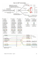
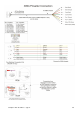
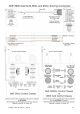
AMF 82-90 (Large Chassis)
As the AMF 82-90 machine uses the same common chassis to control both the Odd and Even machines, the
Duo Camera module only uses one cable to connect to this model of Pinsetter.
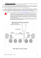
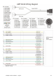
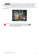
Run the DM-90 cable from the Duo Hardware Module, along the Ball Track, up the kickback, to the 82-90
chassis at the rear of the Pinsetter, and plug into the APS connection at the back of the chassis. The DM-90 cable
gives the Duo Camera Module signals for Cycle, Foul, Rake Down and Pinsetter Status.
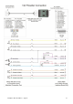
However, it DOES NOT contain signals to turn the Pinsetter On and Off from the Duo unit. To enable this
optional feature, the optional Lane Control Computers must be connected to the MCU (Managers Control Unit) and
software run to enable the MCU commands to be sent from the computer to the Pinsetter, via the MCU.
For more information on connecting the MCU to the Lane Control Computers, see Appendix C in this manual.
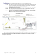
Note: The take data delay in the Fine Tune the Scoring Setup screen must be set to a
allow enough time for the score to be taken and the APS input to the 82-90 chassis to
be driven prior to the pinspotter table starting to move. The default setting is 3.0
seconds for the 82-90 pinsetter model type. The 82-90 must receive the APS scoring
input prior to the table operating, so that any advanced functions such sweep reverse
can occur if necessary. If the table starts moving, it is too late for any advanced
commands to be received.
This Take Data Delay should be set as long as possible to give the maximum time for
any unsteady pins to fall, but not too long so that the 82-90 chassis times out and
ignores 7-10 pick off or short strike cycles