
Installation guide


Chapter 7: Plug In and Setup 46
At the Bowler’s Keypad
The Duo system has the option to communicate with the bowler’s keypads either via a wireless interface, or
alternatively via an extension of the LLAN wired communications cable. Also, you have the option of either one or two
keypads per lane pair.
Depending on whether these options, you must set the following settings on the PC Board inside the keypad.
This will tell the Keypad PCB Board how to behave when a key is pressed.
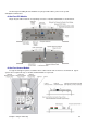
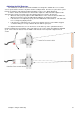
JP2
JP3
¶V
¶V
Wired
Single Keypad
Left
Left
0 (Zero)
0 (Zero)
Dual Keypads - Odd Lane
Left
Left
0 (Zero)
1 (One)
Dual Keypads - Even Lane
Left
Left
0 (Zero)
2 (Two)
Wireless
Single Keypad
Right
Right
0 (Zero)
4 (Four)
Dual Keypads - Odd Lane
Right
Right
1 (One)
0 (Zero)
Dual Keypads - Even Lane
Right
Right
2 (Two)
0 (Zero)
Please note: No other combination of channels is valid.
Wired Keypads
The advantage of wired keypads is they afford greater reliability, however there is more work to do (and
therefore expense) at the time of installation.
For all wired keypads, either single or dual, you must first verify that the jumper for JP2 and JP3 are set to the
Left. This will activate the communications drivers on the PC Board to send the signal via the LLAN cable.
Single Wired Keypads
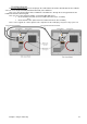
Remove the battery pack connector and plug in the LLAN cable from the Duo CPU Module into the LLAN IN
connector on the Keyboard PCB (Printed Circuit Board).
Then, set the Channel Number on both the Rotary DIP switches to 00. (Zero on the 10’s switch and Zero on
the 1’s switch) When this is done, the keypad will send out a signal to the Duo CPU module whenever a key is
pressed, without specifying Odd or Even Lane.