Aftermarket LCD Upgrade Installation Guide P/N 400-283-301 Revision A Issue Date 4/27/2009
Aftermarket LCD Upgrade Manual ii P/N 400-283-301 Rev A
Aftermarket LCD Upgrade Manual Aftermarket LCD Upgrade Manual Rev. A Part Number 400-283-301 Summary of Changes Change No. ECR No. Original 09-0112 List of Effective Pages Page All Change No.
Aftermarket LCD Upgrade Manual ALL RIGHTS RESERVED All rights to this installation guide including the diagrams, figures, and technical specifications are the property of QubicaAMF Bowling Products, Inc. Reproduction or transmission of any of the material contained in this manual without the prior written permission of QubicaAMF Bowling Products, Inc. is strictly prohibited.
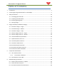
Aftermarket LCD Upgrade Manual Table of Contents 1 Introduction ................................................................................................................................. 7 2 Converting Scoring Overhead CRT’s to LCD displays ................................................................... 7 3 Safety Precautions ..................................................................................................................... 10 3.1 Discharging the CRT Tube .................
Aftermarket LCD Upgrade Manual 7 Making the Right Connections ................................................................................................... 31 7.1 Accuscore Plus No TV / No Drink Light ............................................................................. 32 7.2 AccuScore Plus (C-90) Existing Ads Channel TV ................................................................ 33 7.3 Accuscore Plus (C-90) Enhanced TV and Drink Light ...................................................
Aftermarket LCD Upgrade Manual 1 Introduction Congratulations on your purchase of this QubicaAMF Product. To begin, we will discuss the layout of this manual. Following this Introduction, the second section discusses what to expect from your upgrade to LCD displays, and important considerations you need to be aware of. The next section, Safety Precautions, contains safety instructions and procedures necessary for the removal of existing equipment and installation of your new product.
Aftermarket LCD Upgrade Manual 3) Problems you might ignore on the old CRT like a minor flicker in the display will become quite annoying with the LCD. The barely noticeable twitch becomes a twosecond blink if you don’t clean up the signal. Putting a new windshield in your car gives you a clearer view but it doesn’t stop the wheel shimmy or the engine from burning oil. Be prepared to diagnose and repair the problems that become magnified by the new display.
Aftermarket LCD Upgrade Manual electrical panel. That same ground bus should have another green wire that extends to the ground connection on the IG outlet on the curtain-wall into which the scoring is plugged. While this isolated ground stuff may seem irrelevant for utilitarian wiring, it’s very important for (especially older) scoring systems with remote video displays. Don’t plug other stuff into the scoring power.
Aftermarket LCD Upgrade Manual 3 Safety Precautions 3.1 Discharging the CRT Tube The monitor’s CRT (Cathode Ray Tube) must be discharged. Follow the steps below to discharge the CRT. CRT monitors use lethal high-voltage. Use caution when working around these tubes (especially around ladders). Read and understand all safety requirements when working on CRT monitors! Do not work on this product alone. Make certain another capable person is present to assist in the event of injury.
Aftermarket LCD Upgrade Manual 3.2 Preparing Your Work Area You will need the following items: Scaffolding with wheels (to support 400lbs) Phillips head screwdriver Flat blade screwdriver 7/16, 1/2 inch open end wrenches Wire cutters Installation instructions Large piece of cardboard to place both CRT’s Assemble scaffolding according to manufacturer’s directions. Position the scaffolding under the overhead to be changed out.
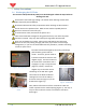
Aftermarket LCD Upgrade Manual Carefully lower the monitor from the scaffold and place front down on a piece of cardboard. Repeat this step for the other monitor. 3.1 Existing Hanger Make certain at least two people are available to support the hanger. Open the quick links on one side and carefully remove the hanger from the chain support. Repeat on the other side and lower cautiously to the floor, out of the way.
Aftermarket LCD Upgrade Manual P/N 400-283-301 Rev A 13
Aftermarket LCD Upgrade Manual 14 P/N 400-283-301 Rev A
Aftermarket LCD Upgrade Manual 4.
Aftermarket LCD Upgrade Manual 4.
Aftermarket LCD Upgrade Manual 4.
Aftermarket LCD Upgrade Manual 4.
Aftermarket LCD Upgrade Manual 4.
Aftermarket LCD Upgrade Manual 4.
Aftermarket LCD Upgrade Manual 4.
Aftermarket LCD Upgrade Manual 4.
Aftermarket LCD Upgrade Manual 4.
Aftermarket LCD Upgrade Manual 4.
Aftermarket LCD Upgrade Manual 4.
Aftermarket LCD Upgrade Manual 4.
Aftermarket LCD Upgrade Manual 5 Component Identification 5.1 LCI S-Video Interface Many of the Aftermarket LCD upgrade packages utilize an S-Video interface. If your package includes this interface, refer to the pictures on this page and also Section 7 – Making the Right Connections for hookup assistance. Figure 3 – 283-200-303 Qubica VDB Connections Figure 4 – 283-200-301 AccuScore Plus Connections 5.1.
Aftermarket LCD Upgrade Manual 5.2 Serial Monitor Control Box The Serial Monitor Control Box is used in cases where the scoring system provides control of TV (Ads) function. Connections are made from scoring control to the green terminal strip (TS) (pictured below center) and to the monitors RS-232 (SERVICE) connection (DB-9). At right is a portion of drawing 400-283-302-05, showing the connections to the serial monitor control box.
Aftermarket LCD Upgrade Manual 6 Detailed Wiring Instructions 6.1 Power Control Accuscore +/ Qubica The power plug for the monitor is connected to the power relay cable (283-200-154), which in turn is connected to the power outlet strip (283-200-019). The power control cable (283200-172) is connected at the S-Video Interface box and the monitor power relay (283-200153).
Aftermarket LCD Upgrade Manual 6.2 Power Off with Conqueror If you have QubicaAMF scoring there is a CD included (400-283-317) that will install files on your system to enable the LCD’s to power off completely. Insert this CD in your Conqueror computer and follow the prompts. This process puts an advertising file on your system and subsequently displays a help file. Follow the instructions in setting up your system to enable Conqueror to shut down your monitors. 6.
Aftermarket LCD Upgrade Manual 7 Making the Right Connections Please select the correct diagram for your application. You will use this diagram as it applies to the options you have purchased to assist you in connecting your LCD properly. Section Drawing Number 400-2837.1 302-01 Heading Title Drawing Description Page Accuscore Plus No TV / No Drink Light Replace AMF Accuscore Plus overhead with 32” or 42” LCD monitors using the 283-200-301 LCI. No TV and No Drink Light 32 7.
Aftermarket LCD Upgrade Manual 7.
Aftermarket LCD Upgrade Manual 7.
Aftermarket LCD Upgrade Manual 7.
Aftermarket LCD Upgrade Manual 7.
Aftermarket LCD Upgrade Manual 7.
Aftermarket LCD Upgrade Manual 7.
Aftermarket LCD Upgrade Manual 7.
Aftermarket LCD Upgrade Manual 7.
Aftermarket LCD Upgrade Manual 7.
Aftermarket LCD Upgrade Manual 7.
Aftermarket LCD Upgrade Manual 7.
Aftermarket LCD Upgrade Manual 7.
Aftermarket LCD Upgrade Manual 8 Power Up & Verify Operation Before applying power, double check all connections. Turn on your scoring chassis, the breaker on overhead and the power strip. The LCD will display a blue power light if the LCD has power but has not been turned on. When powering up, the LCD will display the Qubica logo screen. Once the logo has turned off, press the button on the supplied remote (or on the front of the monitor).
Aftermarket LCD Upgrade Manual 4. Go down to the Panel Size option and press the right arrow button. 5. This will bring up the screen at right. Here you will adjust the horizontal and vertical sizing using the appropriate control. Please note that if your scorer connects to the VGA connection of the monitor, these adjustments will not affect your display. 6. Once you have adjusted the image for optimum sizing, return to the second menu by pressing
Aftermarket LCD Upgrade Manual 8. Once you have satisfactorily setup the screen for size and centering, go back to the first menu and enter 9632. If you have QubicaAMF scoring, you will need to make sure the option at the bottom of this screen (Set ID), is set to 1. 9. Once you have completed these adjustments, go to 8.1.3 Common Adjustments. 8.1.2 VGA (RGB) 1. Make sure your monitor is in VGA mode (Press the button and select VGA). 2.
Aftermarket LCD Upgrade Manual 5. If you are experiencing “tearing” on the top of your screen (in VGA mode) you may need to adjust the coast start and coast end. Please follow the directions in section 8.1.1 (steps 1 & 2) to get to this screen. At the Video option, press the right arrow. Make note of what the values are for both of these settings as it is possible to over adjust them which may result in a loss of the display. If this occurs, reset the values to what they were prior to any changes.
Aftermarket LCD Upgrade Manual 9 Drink Light 48 P/N 400-283-301 Rev A
Aftermarket LCD Upgrade Manual 10 Troubleshooting LCD Issues Possible Problem Corrective Action No picture on LCD Verify the Power light is on for all components. The LCD’s and Monitor Control Box (if present) have a power indicator. Make certain the main disconnect has been turned on. Verify the power strip has power and that all items have been plugged in to the power strip. No picture on odd channel. Error message “No Signal” or “Not Supported” Flexscore CPU must have the video config set to 75.
Aftermarket LCD Upgrade Manual Hanger Issues Possible Problem Gap between LCDs is too Monitors not centered great. Monitors appear crooked 50 Hangers brackets mounted equally Corrective Action Move mounting plate on LCD.