YTL-140-701 30 Ton Log Splitter Brute is a trademark of Briggs & Stratton Power Products Group, LLC and is used under license.
Table of Contents General Warnings and Rules ................................................................................ 3 Hazard Signal Word Definitions............................................................................. 4 Controls and Features Identification ...................................................................... 5 Assembly Instructions ........................................................................................... 7 Operation Instructions .........................
GENERAL WARNINGS READ and UNDERSTAND this manual completely before using 30 Ton Log Splitter. Operator must read and understand all safety and warning information, operating instructions, maintenance and storage instructions before operating this equipment. Failure to properly operate and maintain the log splitter could result in serious injury to the operator or bystanders. Operation Warnings Do not at any time carry passengers, sit or stand on the log splitter.
Hazard Signal Word Definitions This is the safety alert symbol. It is used to alert you to potential personal injury hazards. Obey all safety messages that follow this symbol to avoid possible injury or death. DANGER DANGER indicates an imminently hazardous situation which, if not avoided, will result in death or serious injury. WARNING WARNING indicates a potentially hazardous situation which, if not avoided, could result in death or serious injury.
Controls and Features Identification Read this owner’s manual before operating the equipment. Familiarize yourself with the location and function of the controls and features. Save this manual for future reference. 1. 2” Coupler – Attaches the log splitter to the 2” ball 2. Storage Tube – Storage for Owner’s Manual and small tools 3. Hydraulic Cylinder – 4.5” x 24.5” 4. Control Valve – Controls the forward and backward movement of splitting wedge 5. 8” Wedge 6. 4-way Wedge –Optional use 7. Beam 8.
WARNING Read and follow all instructions for assembly and operation. Failure to properly assemble this equipment could result in serious injury to the user or bystanders, or cause equipment damage. Engine Shipped Without Oil. Before starting engine, fill with SAE 10W-30 motor oil. See engine manual for engine oil capacity. Hydraulic Oil Tank is Shipped Without Oil. When adding oil verify the oil level reads 1 from the top of hydraulic oil tank if marking is not shown fill to the neck.
Assembly Instructions STEP 1: Wheel Assembly 1. Attach the wheel (#35) to the oil tank axle (#44) using a conical roller bearing (#81), flat washer Ø20 (#70) and tighten the wheel with the hex slotted nut M20 (#37). Lock the hex slotted nut M20 (#37) in place using the cotter pin Ø4x36 (#73). Install the axle cap (#41) on the end using rubber hammer. Note: flat washer Ø20 (#70), hex slotted nut M20 (#37) and cotter pin Ø4x36 (#73) are already on reservoir axle (#44), need take out then to assemble.
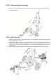
STEP 3: Attach the Beam Assembly 1. Attach the beam assembly (#17) to the hydraulic tank and secure using the hinge pin (#18) and R-Pin Ø3 (#21). STEP 4: Attach Engine 1. Install the engine place four polyurethane block (#71) and big flat washer Ø10 (#72) between the mounting plate and engine. 2. Position the engine (#33) over the blocks and secure it to the mount plate put the hex bolt M8x65 (#46) through the bottom of the plate (bolt should go through blocks, flat washer and engine base).
STEP 5: Attach Hydraulic Hose, Storage Tube, Log Cradle and Fender 1. Put O ring Ø11x2.5 (#19) on the gear pump outlet connector (#23), attach the hydraulic hose (#16) to the gear pump outlet connector (#23). 2. Put O ring Ø17x2.5 (#68) on the external filter connector (#50), attach the hydraulic hose (#7) to the connector (#50). 3. Remove the hex bolt M6x90 (#75), big flat washer Ø6 (#76) and nylon lock nut M6 (#77) from the tow bar.
STEP 6: Attach 4-way Wedge (Optional use, will not work with all wood) 1. Attach 4-way wedge (#87) to the wedge (#14), pass the steel wire rope (#89) around the piston rod and set it on the O lock ring (#88). ATTENTION: Cross wedge for HORIZONTAL SPLITTING use only STEP 7: Add Engine Oil 1. Make sure the log splitter is on a level surface. 2. Remove oil fill cap/dipstick to add oil. 3. Refer to the separate owner’s engine manual for the amount needed of SAE10W-30 engine oil; replace oil fill cap/dipstick.
CAUTION Fuel and fuel vapors are highly flammable and extremely explosive. Fire or explosion can cause severe burns or death. Unintentional startup can result in entanglement, traumatic amputation or laceration. Only use regular unleaded gasoline with a minimum 85 octane rating. DO NOT mix oil and gasoline together. Fill tank approximately ¼” below the top of the tank to allow for fuel expansion. DO NOT fill fuel tank indoors or when the engine is running or hot.
Operation Instructions WARNING Before operating or using the log splitter, review the instructions below and all safety information. Failure to follow these instructions may result in property damage or injury to the operator or bystanders WARNING ALWAYS use the log splitter for its intended use. ONLY use the log splitter to split wood logs, length wise with the grain. NEVER modify, alter or change the log splitter in anyway, modifications will void the warranty.
NOTE: Serious accidents can happen when other people are allowed inside the work zone. Keep everyone else outside the work zone while operating the control lever. 7. Always wear safety gear, eye protection, gloves and work boots when operating the log splitter. 8. Start the engine and make sure the log splitter is on level ground before operating. NOTE: The hydraulic oil needs to be above 10°F (-12C°) before starting the engine. Cold hydraulic oil can damage the hydraulic pump.
12. Make sure hands are clear from the wedge and crush hazard areas. CRUSH WARNING Wedge can cut through skin and break bones. Keep both hands away from wedge and beam slide. Serious accidents can happen when other people are allowed inside the work zone. Keep everyone else out of the work zone while operating control lever. DO NOT wear loose clothing. It can get tangled in moving parts of log splitter. Only use the log splitter in daylight so you can see what you are doing. 13.
Operation Instructions - 15 -
Maintenance and Storage CAUTION Improper maintenance and storage of the log splitter may void your warranty. MAINTENANCE Before performing maintenance, the log splitter must be placed in maintenance mode. Turn off the engine and move the control lever forward and backwards to relieve the hydraulic pressure. After performing any maintenance, make sure all guards, shields and safety features are put back in place before operating the log splitter.
Troubleshooting Problem Cylinder rod will not move SOLUTION: A,D,E,H,J Slow cylinder rod speed when extending or SOLUTION: A,B,C,H,I,K,L retracting Wood will not split or splits extremely slowly SOLUTION: A,B,C,F,I,K Engine bogs down during splitting SOLUTION: G,L Engine stalls under low load condition SOLUTION: D,E,L,M Engine starts problem SOLUTION: N Cause Solution A-Insufficient oil to pump Check oil level in reservoir B-Air in oil Check oil level in reservoir C-Excessive pump inlet vacu
Specifications Ram Force .................................................................................................... 30 Ton Cycle Time.................................................................................................... 13 Sec Wedge Size .................................................................................... 8” Harden Steel Gear Pump ..................................................................................................2-Stage Hydraulic Oil ...................
Parts Drawing & Parts List - 19 -
Parts Drawing & Parts List Ref# Drawing No. 1 9101-05010-DX8.8 2 Description Qty Hex Bolt M5x10 4 9121-06010-FH Inner Hex Cone Point Set Screw 1 3 LSP30B-03000 Cylinder 1 4 LSP25-00001-DX Metal Hydraulic Hose 1 5 LSP25-00005-DX R Pin Ø4.
Ref# Drawing No. Description 38 LSP25-00019-DX Angle Connector 1 39 LSP25-00022-DX Inner Oil Filter 1 40 9404-03030-DX Cotter Pin Ø3x30 3 41 LSP25-00009-DX Axle Cap 2 42 LSP25-00021-DX Rubber Washer 1 43 LSP25-10008-FH Wire Snap rings for shaft 1 44 LSP30MD-03000 Oil Tank 1 45 9301-06000-DX Flat Washer Ø6 6 46 9101-08065-DX8.8 Hex Bolt M8X65 4 47 9101-06020-DX8.
Ref# Drawing No. Description 76 9302-06000-DX Big Flat Washer Ø6 6 77 9206-06000-DX Nylon Lock Nut M6 3 78 9206-14000-DX Nylon Lock Nut M14 1 79 LSP25-09002 Filter 1 80 LSP25-14002 Oil Seal 2 81 L44643 Conical Roller Bearing 4 82 9101-12035-DX8.
Limited Warranty Warranty For two years from the date of purchase YTL International will replace for the original purchaser, or repair the log splitter. The warranty will not apply to any unit which was not assembled correctly, misused, overloaded or which has been used or operated contrary to our instructions, or which has been repaired or altered by anyone other than an authorized representative.