BRX2004A/BRX2008A USER GUIDE MOBILE DIGITAL VIDEO RECORDER With Advanced Analytic Software 1st Edition Thank you for purchasing D-TEG BRX2004A/BRX2008A. Please familiarize yourself with the capabilities your new Mobile DVR can provide by reading this manual carefully. Please be careful when using your new device while driving Your new device may be upgraded with new functions and features periodically, please check our website (www.d-teg.com or www.d-teg.
Preface Notice Any unauthorized use of this guide or its contents is prohibited. The contents may be changed without notice. The contents of this user guide are comprehensively designed to provide adequate information to set up and operate the purchased device. Please contact D-TEG if you have any questions or find any omissions. If you find any missing pages in this users guide, please contact your dealer or D-TEG for a replacement.
Table of Contents Safety Advice ......................................................................................................................................................... 7 1. Contents .............................................................................................................................................................. 9 2. Specifications .....................................................................................................................................
3-3.SYSTEM Settings ................................................................................................................................ 38 3-3-1. SYSTEM / DATE/TIME/LANGUAGE ............................................................................ 39 3-3-2. SYSTEM / USER MANAGEMENT .................................................................................. 40 3-3-1. SYSTEM / SERVICE .......................................................................................................
Search ............................................................................................................................................................ 58 6. 6-1. Calendar Search ................................................................................................................................ 58 6-2. Event Search ....................................................................................................................................... 58 7. Blur Function ............
Appendix D) Specifications ........................................................................................................................
Safety Advice SAFETY ADVICE CAUTION RISK OF ELECTRIC SHOCK DO NOT OPEN CAUTION: TO REDUCE THE RISK OF ELECTRIC SHOCK, DO NOT REMOVE COVER. NO USER-SERVICEABLE PARTS INSIDE. REFER SERVICING TO QUALIFIED SERVICE PERSONNEL. Please make sure you follow the safety advice/instructions given in the user guide. CAUTION RISK OF EXPLOSION IF BATTERY IS REPLACED BY AN INCORRECT TYPE. DISPOSE OF USED BATTERIES ACCORDING TO THE INSTRUCTIONS. Battery for RTC (Real Time Clock) inside.
GPS Reception 1. Activate the product in an area without large buildings to improve GPS reception. The commercial purpose GPS has the average range error of more than 15 meters and the range error could be more than 100 meters due to environmental conditions like buildings, roadside trees etc. 2. The temperature range for optimum operation of the GPS receiver in your car is -10 ~ 50°C. 3.
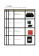
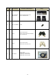
1. Contents The following items are included with the BRX2004A or BRX2008A. No.
No.
No.
2. Specifications Category Video Inputs (max) Model BRX2004A 4 Video Out Audio Inputs (max) Audio Out Video Format Audio Format Recording Resolution Recording FPS Alarm In Alarm Out LED indicators Removable Storage External Device LAN G-Sensor Serial Port Signal Port Input Interface Power Out Application Language SW Allowable Temperature Range Allowable Humidity Range Max Shock Tolerance Power/Consumption Weight (approx.) Dimensions Remarks BRX2008A 8 1 4 8 1 H.264 G.
Interfaces Removable HDD/SSD Slot SD Video Out Audio Out External Power Out LED BEEP Button IR Receiver Video Inputs Audio Input Car Signal Alarm In Alarm Out Serial Port 1 Serial Port 2 Serial Port 3 USB LAN Power In External Power Out IO – Front 2.
3. BRX2004A Overview 3-1. Front ① ② ④ SD ▼ ⑥ ⑤ ⑧ ⑦ ⑨ ① Cover Lock ② LED Indicator Lights [POWER]: Illuminated when the BRX is powered (Green LED) [REC]: Illuminated when recording (Orange LED) [ALARM]: Illuminated in any fail conditions (Red LED) [LAN]: Illuminated when connected to the network (Orange LED) At power on, the POWER LED will illuminate immediately and the BRX will go into system check. Once device is operational, the REC LED will also illuminate.
[FN] + [∧]: Upload device settings * Uploading Device set up: Store your device settings onto a SD Card or USB memory stick using the PC Viewer, plug in the memory media into the device while in operation, pressing the [FN] + [∧] together will upload and change the settings. [FN] + [∨]: Download device settings and log data * Downloading Device set up: Plug in a SD Card or USB memory and press the [FN] + [∨] together to download the settings Note 1.
“dvr_config_down”, and in the sub-folder “MAC_Mac Address“ as files: “dvrid.ini, setting.ini, version.ini, system.log” B. Uploading the setting files Set and store device setting files using the PC Viewer (For instructions refer to section 10-2) Insert the SD card until it locks and press [Fn] and [∧] simultaneously. During the upload, the device will sound three short beeps continuously Two short beeps will sound when upload is finished. One short beep will sound if there is an error.
3-2. Rear ① ② ③ ④ ⑤ ⑥ ⑦ ⑧ ⑨ ⑩ ① Power Connector Use the included power cable bundle for this connection, the battery cable connects to the battery power and the ACC cable connects to the ignition or main power switch. ② Car Signal Connector Use the car signal cable bundle for this connection. Connect the appropriate car signals to the labeled cables.
4.
4-2 Option II (Nagoya example) 19
4-3 Option III (Tokyo example) 20
Main Unit Set Up 1. Live Screen 1) The device will become operational in one to two minutes after the power on. Note 1. When the device is properly set up and powered on, power on and off can be controlled by either the main power switch or the ignition, depending on your own connection arrangement. 2. At power on, the unit will automatically self-check. If required, it may re-boot in which case it will take up to 5 minutes for the device to be operational. 3.
Video Loss, No Camera Detect Alarm in 4 Motion Detection Detect Alarm in 5 Audio Record Detect Alarm in 6 Continuous Record (RED) Detect Alarm in 7 Event Record (YELLOW) Detect Alarm in 8 Detect Alarm in 1 Activate Alarm out 1 Detect Alarm in 2 Activate Alarm out 2 Detect Alarm in 3 Detect G-sensor variability 2. Information Screen 1) Press [STA] four times to switch to the Information Screen.
i. Left turn signal: Left ii. Right turn signal: Right iii. Brake pedal: Brake iv. Reverse gear: Reverse v. Emergency: Left & Right * Multiple signal display is possible ⑨ G-Sensor * When installing your device, configuring your G-sensor is essential. Refer to Appendix B for the configuration values and select the correct angle setup for each axis. ⑩ RPM: Displays engine RPM measured by RPM pulse.
5) Within each directory, there are sub-directories that can be accessed by pressing [∨][∧] and then [MENU] 6) Press [ESC] to return to previous stage. Note The password can be changed by going to [MENU -> SYSTEM -> USER MANAGEMENT -> PASSWORD]. Press [MENU] to change the password. Use a combination of [>], [<], [∨], [∧] as a password then press [MENU] to set. If left empty, no password will be set. Repeat this process to confirm. Press [ESC] to return to previous stage and exit MENU. Note 1.
3-1. Device Setting Sub-categories are camera, signal, G-sensor, remote control, display, and external device. Press the [∨] and [∧] keys to move between selections. When the subcategory you wish to set-up is highlighted in yellow, press [MENU] to enter configuration. Press [ESC] to return to previous screen. 3-1-1. Device / Camera Move between the set-up selections using the arrow keys Channel: Select the channel for configuration using the arrow keys.
Note 1. The channels that are turned off cannot be viewed live nor will it be recorded. 2. When there is a recording failure, the video loss icon will show on the channel’s live screen and the alarm LED will light up. 3. When a channel is activated without a connected camera, the video loss icon will show on the channel’s blank screen and the alarm LED will light up. To avoid this, please turn off all channels that are not being used. Camera Title: Each camera can be named separately, e.g.
3-1-3. Device / G-sensor Depending on the installation location and slant, set the “(X), (Y), (Z)” axis angles using the information provided in REF2 below. Caution! 1. When using an HDD, postion the device in an upright positon only 2. The postions and adjustments in REF2 are ONLY for when using SSDs. The “X, Y, Z” axis angles can be set at “0/90/180/270”. Set the “Acceleration(FX), Deceleration(RX), Turn(Y), Vertical(Z)” trigger levels from “0.1G ~ 1.0G”.
“REF2. Suggested axis adjustments by device positions” ONLY for when using SSD! HDD users must postion the device upright! Driving direction F: Front B: Bottom RR: Rear R: Right-side T: Top L: Left side 1) When device is in an upright position T F R L T RR RR R B B X:0, Y:0, Z:0 X:0, Y:0, Z:180 T T F L L RR B B X:0, Y:0, Z:270 X:0, Y:0, Z:90 Caution! 1. When using an HDD, postion the device in an upright positon only 2.
2) When device is in an upside-down position B F L RR RR R T T X:180, Y:0, Z:0 X:180, Y:0, Z:180 B B F L B R R F RR T T X:180, Y:0, Z:270 X:180, Y:0, Z:90 L 3) When device is in a sideway position with the TOP to the left R F L T L RR RR T L X:270, Y:0, Z:0 R X:270, Y:180, Z:0 F RR T R R RR X:270, Y:90, Z:0 T F 29 F L
4) When device is in a sideways position with the TOP to the right L F R B RR RR B F R X:90, Y:0, Z:0 L X:90, Y:180, Z:0 F RR R B L B L RR X:90, Y:90, Z:0 R F 5) When device is in a sideway position with the TOP facing front L T F R B T R X:90, Y:0, Z:270 RR B L X:270, Y:0, Z:90 RR F T R B T RR X:180, Y:90, Z:0 30 L F B
6) When device is in a sideway position with the TOP facing rear R B F L T B L X:270, Y:0, Z:270 RR T R X:90, Y:0, Z:90 RR F B L T B R F RR X:0, Y:90, Z:0 31 TOP
CAUTION! Never install the BRX2000 device with the front facing down. This will lead to SSD recording malfunctioning and damage to the device. 3-1-4. Device / Remote Control You can activate and deactivate the remote control using the [>] and [<] keys. When activated, the remote control receiver needs to be chosen between “Internal” when using the infrared receiver on the device itself and “External” when using an optional external receiver. When a remote control is not in use, set to “OFF”.
- This sets the initial screen that will be displayed at power on and can be chosen among these options: “1 / 2 / 3 / 4 / 5 / 6 / 7 / 8 / 2×2‐1 / 2×2‐2 / 3×3” - “2×2‐1” will show channels 1 ~ 4 split into 4 screens and “2×2‐2” will show channels 5 ~ 8 split into 4 screens. EMS Alert Unit Note The EMS Alert Unit is an optional accessory and can be purchased separately. - USE: Select “ON” using the [>] and [<] keys.
Serial Port Usage * The BRX series has three serial ports: [S1/S2/S3]. S1 (Serial Port 1) is used solely for debugging and maintenance while S2 (Serial Port 2) and S3 (Serial Port 3) may be used to connect various external devices such as GPS, External IR receiver, Tachometers and the EMS Alert unit. - SERIAL2 – DEVICE and SERIAL3 – DEVICE: Use the arrow keys to select connected external device to activate.
3-2. Record Settings Sub-categories for record settings are Quality & Resolution, Channel Setup, and Record Options. Press the [∨] and [∧] keys to move between selections. When the subcategory you wish to set-up is highlighted in yellow, press [MENU] to enter configuration. Press [ESC] to return to previous screen. The total recording time depends on the size of the data storage device and record settings. Please refer to Appendix C for the recording timetable. Note 1.
3-2-1. Record Settings/ Quality & Resolution RESOLUTION: Select among “D1 (704*480), HD1 (704*240), CIF (352*240)” using the arrow keys.
3-2-2. Record Settings / Channel Set Up Set recording mode, frame rate, and audio per each channel CHANNEL - First, select the channel you wish to configure using [<] and [>] keys. - Second, use the [∨] and [∧] keys to move between “RECORD, FPS, AUDIO”, the specific settings will only apply to the selected channel. - Configure all cameras (channels) that are connected to the main unit. RECORD - Choose between “OFF/Normal/Event /Normal + Event” - If set to “OFF”, the channel will not be recorded.
Note 1. Since the total number of frames change with resolution, if the resolution is changed the total number of frames will change and the FPS will need to be re-set. To avoid redundant operations, please set the resolution before setting the FPS. 3. If the FPS is set before the resolution is set, please go back and re-set the FPS before use. Audio - All channels can record audio. - To record audio, a camera with an internal microphone should be connected to the main unit and the audio turned on.
Important configurations such as date, language, password, format, default settings can be set here. When changing certain configurations, side effects such as data loss, video loss, or limited access may occur. So please use caution when changing any system settings. 3-3-1. SYSTEM / DATE/TIME/LANGUAGE SYSTEM TIME: Configures date and time. - Press the [MENU]. When the year is highlighted in red use the [∨] and [∧] keys to change the year.
- If set for a specific time: “0~23”, time will synchronize at that time. In addition, if the GPS time cannot be found at that time, the device will automatically synchronize as soon it has reception. SPEED UNIT - This component can only be set using the PC Viewer. LANGUAGE - The BRX2000 series offers these language settings “English/ Korean/ Japanese/ Chinese/ Simplified Chinese/ Russian/ Portuguese” 3-3-2.
FORMAT - Select the data storage medium “HDD (SSD) or SD card” you wish to format and press [MENU]. There is no SSD selection. If using a SSD, select HDD. - After selecting, you will be asked, “Are you sure? NO”. Use the [>] or [<] to select “Are you sure? YES”. Then press [MENU] to start formatting. - A progress bar will show the status of the format and will close when complete. Caution! 1.
- Copy the new firmware into the “dvr_program” folder. - Extract the SD card (or USB Memory stick) and insert it into the main unit. - In the upgrade menu, choose which media “SD card/USB(Rear)”you will use to upgrade and press [MENU]. - The device will start upgrading immediately and once upgraded, the device will automatically reboot. * If both SD card and USB memory stick is inserted, priority usually goes to the SD card unless it is specifically chosen.
4. Uploading/ Downloading the Setting File 4-1. Upload The device can be configured with more options using the PC Viewer. - Using the PC Viewer, set up the configurations as needed and then save the settings to an SD card (or USB memory stick). Refer to Chapter 10 for instructions. - Insert the SD card (or USB memory stick) into the main unit and press both [FN] and [∧] together. - While uploading, you will see a progress bar and hear a sequence of three beeps until complete.
PC Viewer Software Instructions This section is about how to install the PC Viewer Software Program and instructions on how to use the program. The provided PC Viewer must be used to access the recorded data, including all video and audio data. Once accessed, the video and audio data may be converted into an AVI file for your use. 1. System Requirements For the PC Viewer to operate properly, the following system requirements need to be met. 1-1.
2. Installation of PC Viewer Software Insert the PC Viewer Software CD and run the [SETUP.EXE] file by double clicking it. Choose the language of use and follow the instructions on the screen. When complete, the [BRX2000A] execution file can be found by going to [Start], [Programs], and [DVRViewer BRX200A]. If you check the [Create a desktop icon] option during the installation, the below icon will be created on your desktop. PC Viewer Execution Icon 3.
3-1.
3-1-1.
3-1-2.
4. Playing 4-1. Connecting HDD (or SSD) Connect your removable HDD (or SSD) to your PC with the included SATA to USB adaptor. Check if the removable disk is properly connected and recognized. Caution! 1. Only use the SATA to USB adaptor provided with the BRX unit. 2.
Select the search options “Normal/ Event/ Other sub-options” from the left bottom corner. The dates that have recorded video data for that option will be filtered and are highlighted in blue. Choose the date you wish to check. The chosen date will be highlighted in yellow. * Search options - Normal: Normal recorded data - Event: Event recorded data - Motion: Data with activated motion triggers - Signal: Data with activated signal (turns, brakes, etc.
Control Buttons Indicator and Time Slide Bar Playback can be operated using the control buttons. You may also jump to different times by clicking other time slots that are highlighted in orange and by sliding the time slide bar on the bottom for more precise changes. * Refer to section 3-1-2 for more detailed description of the control buttons. You can change the date by clicking the calendar search button tool bar. It will take you back to the initial search screen.
4-3. Select Layout The BRX2008A (BRX2004A) can be connected to a maximum of 8 (4) cameras and microphones and all input data can be recorded simultaneously. Click the “Select Layout” button and choose with display layout you wish to use. The screen can be split into “2/3/4/5/5/6/8/9” sections.
You can also switch the channel views around by dragging and dropping to different locations on the screen. To access other viewing options, right-click on your mouse to open and set up. - Display ratio: Choose from “Original/TV(4:3)/Fit to Window”. - Zoom: Choose from “1x/2x/4x/8x”. The zoom will only be applied to the view that the arrow cursor was over. - Mirror Mode: The view will be flipped to reverse left and right. - Camera: Choose from channels “1∼8”.
5. View Information The BRX records not only the video and audio from the connected cameras but also GPS location information, speed, time, signals, RPM, G-sensor values, and alarms. All recorded information can be accessed and analyzed using the PC viewer. 5-1. Sensor Information While playing back the selected data, click the View Information button to view the below Sensor Information screen.
the main unit) is shown with the data reference point zero-point calibrated and positive shocks as (+) and negative shocks as (-) - Speed: GPS measured speed is displayed in red while the speed-pulse measured speed is displayed in grey. - RPM: Displayed in purple. - All triggers (signals and alarms) are displayed on the bottom of the screen with the grey bar meaning the trigger is activated.
5-2. Analyze Driving Info While playing back the selected data, click the View Information button to view the below Analyze Driving Info screen. From the calendar in the bottom right corner, choose the date you wish to inspect among the dates highlighted in blue. Dates that are not highlighted in blue, do not have the relevant data. All data from the selected date will be automatically chosen from the selection on the right. You can unselect data that you do not need. Click load for access.
5-3. Tracking During the viewing, if you click the tracking button , the below screen will pop up showing a map of the region, the route the in pink, and the location of the vehicle with an orange arrow. 5-4. PC Viewer Display The BRX PC Viewer is composed of a main screen, sensor information screen, driving analysis screen, and the tracking screen. These screens can be displayed independently and their location and size changed to improve use and management of data.
6. Search 6-1. Calendar Search Refer to section 4-2 6-2. Event Search With the BRX, searching and filtering the data is made easy. Utilizing supplementary data such as g-sensor, signals, alarms, speed, and RPM, you can find incidents and events quicker than monitoring the vast amounts of video and audio recordings. Click the Event Search button: Select the search range. Check the components: G-sensor, signals, alarms, speed, etc., that you wish to filter and click [Search].
Double click the data you wish to inspect or select the data and click the [GotoVideo] button. The data will be accessed and ready to play back.
7. Blur Function The BRX can be configured to have blurred areas for each channel which can be applied to when backing up the data as a JPG or AVI file and also when playing back on the PC Viewer. Put the video on pause and click the [Blur] button: The Blur set up screen will pop up as below. Using the scroll down, select the camera you wish to set up. On the selected camera view, blur out the area you wish to protect by leftclicking on the sections. You can select multiple areas.
61
8. Data Backup and Printing 8-1. Still frame conversion to jpg This will create a still frame jpg back up file for a certain instance. After finding the precise time you wish to save, pause the playback and click the [Save jpg] button: and the below screen will pop up. Choose the camera inputs you wish to save. Check all the information you wish to include from the options shown. The selected information will be imprinted on the image itself.
8-1. Video conversion to AVI file Pause the video at where you wish to start saving and click the Save AVI button: . Check the cameras you wish to convert into an AVI file and if you wish to include audio, check the [Audio Ch] box and scroll down to the channel you wish to include. * Multiple video channels can be converted but only one audio channel can be recorded and that one audio channel will be included in all AVI conversions. Program the period you wish to convert.
Check all camera images you wish to include in the report. Type the title of the report and any comments about the situation or other reminders. If the Apply Mosaic box is checked, the pre-set blur effect will be applied. When you click [OK], a preview of the report like the one below, will be pop up. After checking all the information, press [Print] to print the report.
9. Backup and Backup list You can back up the recorded data on your PC or other data storage medium. The BRX offers an option to store data by type to ease management of data. You can also input additional data such as DVR ID, User ID, title, and comments to help in administration. 9-1. Backup Click the Backup button: Check all the camera boxes you wish to back up. Set the time you wish to backup.
Choose the folder where the backup files are at the bottom of the screen. (It will automatically show the last folder that was accessed.) Select the report type by scrolling down the options. The files are listed showing the “Date/Time, DVR ID, User ID, Title”. Check the box next to the file you wish to play back click [OK]. The below file list will pop up. Double click the file and video files will show on the PC Viewer as below.
10. Setting Using the PC Viewer, you can configure the BRX main unit as well as the program itself. 10-1. PC Viewer set up Click the Setting Button: DVR Viewer Password:Click the [Set Password] button to set up a password for the PC Viewer. You can use any 4-digit number from 1000 to 9999. If you leave blank, no password will be set. After setting a password, whenever the PC Viewer is run, it will ask for the password. for the below setting window to pop up.
layout by clicking the default layout button: corner of the PC Viewer. on the right upper hand - Default Layout: The program will launch with the Default Layout - Last Layout: The program will launch with the same layout as it was when it was closed. - Layout Interlock: If checked the three windows (Main, Map, and Info) will lock into place and will change as one window. - Soften Image: If checked, the image will be softened when viewed.
10-2. DVR Configuration You can configure the BRX main unit with the keys on the main unit itself but for the full range of settings, you will need to use the PC Viewer. Prepare a SD card or a USB memory stick and connect it to the PC. * Refer to uploading instructions section 4-1. To upload the settings you configured with the PC Viewer. Click the Settings Button: and when the settings window pops up. Click the [NEW] button under DVR Config.
10-2-1. Device Configuration for Camera, Car Pulse, G-sensor, and External Devices. Camera Default Layout Apply Tachometer Data Remote Controller Car Pulse RPM G-Sensor Check Box Cam Title Check all the cameras you wish to use Use the alphabet and numbers to rename (max 10 digits) the cameras. The new names will be displayed on the live screen and all recordings.
B. Set the appropriate angles from “0/90/180/270”, according to the position of the main unit. - Set the trigger levels in each axis direction. These levels will be used to judge over acceleration, over deceleration, sudden turns, and excessive up-down vibrations. - Each trigger level can be set from 0.1G to 1.0G where 0.1G is more sensitive than 1.0G - The BRX has 3 serial ports of which S1 is reserved for maintenance and S2 and S3 can be used to connect other devices.
10-2-2. Record Recording setting including resolution, FPS, quality, can be configured here. Start by selecting either the SD EventRecord, Dual Record, or neither, on the right hand side, as they will influence the range of options for other settings. Then select the Resolution on the upper right side as this will set the maximum amount of Frames Per Second (FPS) on the left side. Note! The SD EventRecord and Dual Record settings decide what data and at what frequency the data is saved on the SD card.
Type total frames that can be used depending on resolution. The recording type is realted to the SD EventRecord Type on the right. You need to set this prior to selecting the Type here. To set, check the SD EventRecord, select the type from “NONE or DTEG (RESONANT is a specific type which should not be used). After selecting the SD EventRecordType, you can choose to leave the SD EventRecord on by leaving the check or off by unchecking.
Password Overwrite SD EventRecord Dual Record Pre and Post times are only valid in event recording mode. An additional password can be set for the recorded data using a 4 digit password from 1000 ~ 9999. If a password is set, keep a record in a safe place. Without the password, you will not be able to view the data. If this box is checked, when the HDD or SSD is full, it will start overwriting from the oldest data. If the box is not checked, the BRX will stop recording.
10-2-3. Event The BRX can use different signals as triggers such as Motion, Alarms, Signals, Gsensor, and speed and can also control alarm out and video out. . 10-2-3-1. Motion You can set up the whole camera view or a set region as a motion trigger. Camera Sensitivity Set Grid Select the cameras you wish to use Select from “1~5” where 1 is dull and 5 is sensitive. The default is the whole camera view but a region can be set as below. - The region can be set by using the left button on the mouse.
Record CH AlmOut1, 2 LiveoutCH/ Duration Duration buttons on the bottom. - Select the camera(s) that you wish to record when the motion sensor is triggered. - For example, you can choose camera 1 and 2 to record when motion is detected in camera 1. - The Record CH boxes: “▢▢▢▢▢▢▢▢”are Channels 1 to 8 starting from the left to the right. - Only the channels that are checked in the Device Menu can be selected. - An output alarm, such as a siren, can be used.
10-2-3-2. AlarmInput Seven additional alarm inputs can be given to the BRX. This is the configuration menu for these inputs. Input Channels Title Type Record CH AlmOut1, 2 LiveoutCH/ Duration Check the boxes for the alarms that will be used Use the alphabet and numbers to rename (max 10 digits) the alarms. The new names will be displayed on the live screen and all recordings.
Duration Select how long you wish to display from “5, 10,20, 30, 30, 50, 60, and ∞ seconds” Function 78
10-2-3-3. Signal The BRX can use the car signals as triggers such as turn lights, brake, and reverse. Title Record CH AlmOut1, 2 LiveoutCH/ Duration Duration The default title is set as Left, Right, Brake, and Reverse but this can be renamed (Max 10 digits) as required. - Select the cameras that you wish to record when the motion sensor is triggered. - For example, you can choose camera 1 and 2 to record when motion is detected in camera 1.
10-2-3-4. G-Sensor/Speed Values from the G-sensor, speed, and RPM can be used as triggers. G-Sensor GPS speed Pulse Speed Video Loss System Warning OSD Speed Source Record CH AlmOut1, 2 LiveoutCH/ Duration When the G-sensor exceeds the pre-set values, the be triggered When the GPS speed exceeds the value input here, will be triggered When the GPS speed exceeds the value input here, will be triggered When any camera losses its video, an alarm will go attention.
Duration Liveout Priority setting. Refer to section 10-2-3-5.
10-2-3-5. Liveout Priority When there are multiple triggers, this ranking will be used to decide which output will have priority. Liveout Priority This sets the priority for the 11 types of display that the BRX offers. - 1 has the highest priority and 11 has the lowest. - For example, in the above setting, if channel 3 and channel 4 are both triggered at the same time, channel 3 has priority and the monitor will show channel 3.
10-2-4. System Language Date Format Time Format Speed Format Apply DST TimeZone TimeSync(GPS) DVR ID Select from English, Korean, Japanese, Chinese, Russian, and Portuguese Select from YYYY/MM/DD, MM/DD/YYYY, or DD/MM/YYYY Select from “24H/12H am/pm”. Select from “km/h” or “mile/h”. - Check the box to apply daylight savings time. - Input the start and end date of DST.
10-2-5. EMS (Eco Management System) The data that the BRX uses the EDA (Eco Driving Analyzer) in addition to the PC Viewer to further analyze driving data. It also has an EMS Alert Unit that can be used to display alarms when driving is not economic or safe. SD Record Type Overwrite Max Size (MB) Max count EMS Device Alarm The default is set to “DTEG” and should not be changed unless advised by D-TEG or your supplier.
11. Remove Data Storage Media To safely remove the removable HDD (or SSD), Click the remove the data storage media button: instead of the PC remove hardware button. Click the "remove data storage media" button: . A list with all SSDs (or HDDs) connected with the PC will pop up. Select the data storage media you wish to safely remove. 12. About This shows the PC software version, DVR Firmware version, copyright info and hotkeys. 12-1.
12-2. Hotkeys You can utilize the hotkeys to control the Pc Viewer more efficiently. Click the “About” button: to see the below pop up. Scroll down to view all the shortcut keys.
Appendix A) Shortcut Key list Menu HDD open [F2] File open [F3] Close [F4] Information [F5] Calendar Search [F6] Event Search [F7] Blur settings [F8] Still frame conversion [F9] Video conversion [F10] Print report [F11] Settings [F12] Playback Play/ pause [Space] Play [P] Reverse play [B] Playback speed 0.1/0.
[Shift+8] 3x3 88
Appendix B) Suggested Axis Adjustments by Device Positions Caution! ONLY for when using SSD as data storage, HDD users MUST postion the device upright! Driving direction F: Front B: Bottom RR: Rear R: Right-side T: Top L: Left side 1) When device is in an upright position T F R L T RR RR R B B X:0, Y:0, Z:0 X:0, Y:0, Z:180 T T F L L RR B B X:0, Y:0, Z:270 X:0, Y:0, Z:90 89 F R
2) When device is in an upside down position B F L RR RR R T T X:180, Y:0, Z:0 X:180, Y:0, Z:180 B B F L B R R F RR T T X:180, Y:0, Z:270 X:180, Y:0, Z:90 L 3) When device is in a sideway position with the TOP to the left R F L T L RR RR T L X:270, Y:0, Z:0 R X:270, Y:180, Z:0 F RR T R R RR X:270, Y:90, Z:0 T F 90 F L
4) When device is in a sideway position with the TOP to the right L F R B RR RR B F R X:90, Y:0, Z:0 L X:90, Y:180, Z:0 F RR R B L B L RR X:90, Y:90, Z:0 R F 5) When device is in a sideway position with the TOP facing front L T F R B T R X:90, Y:0, Z:270 RR B L X:270, Y:0, Z:90 RR F T R B T RR X:180, Y:90, Z:0 91 L F B
6) When device is in a sideway position with the TOP facing rear R B F L T B L X:270, Y:0, Z:270 RR T R X:90, Y:0, Z:90 RR F B L T B R F RR X:0, Y:90, Z:0 92 TOP
Appendix C) Recording Time Table 93
Appendix D) Specifications Function Video In Video Out Audio In Audio Out Video Codec Audio Codec Recording Resolution Recording Fps Alarm In Alarm Out LED Removable Storage External Device LAN G-Sensor Serial Port GPS Port Signal Input Interface Power Out Language SW Ambient Temp. Ambient Humidity Shock Tolerance Power/Consumption Weight Dimensions Detail specification 8 Channel : power(DC 12V) included, NTSC/PAL, 1 (Front) 8 Channel 1 (Front) H.264 G.
Front/Rear: Interface Removable HDD/SSD Slot SD Video Out Audio Out External Power Out LED BEEP Button IR Receiver Video Input Audio Input Car Signal Alarm In Alarm Out Serial Port 1 Serial Port 2 Serial Port 3 USB LAN Power In External Power Out IO – Front 2.