
Operating instructions


lation, service, or maintenance may cause fuse to blow. If fuse
replacement is required, use only a fuse of identical size (3 amp)
and type. The control will flash code 24 when fuse needs
replacement.
NOTE: Use AWG No. 18 color-coded copper thermostat wire for
lengths up to 100 ft. For wire lengths over 100 ft, use AWG No.
16 wire.
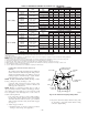
C. Accessories
1. Electronic Air Cleaner (EAC)
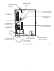
Two quick-connect terminals marked EAC-1 and EAC-2
are provided for EAC connection. (See Fig. 31.) These
terminals are energized with 115v (1.0-amp maximum)
during blower motor operation.
CAUTION: UNIT DAMAGE HAZARD
Failure to follow this caution may result in unit compo-
nent damage.
DO NOT connect furnace control HUM terminal to HUM
(humidifier) terminal on Thermidistat™, Zone Controller
or similar device. See Thermidistat™, Zone Controller,
thermostat, or controller manufacturer’s instructions for
proper connection.
2. Humidifier (HUM)
A quick-connect terminal (HUM) and screw terminal (C
OM
24-v) are provided for 24-v humidifier connection. (See Fig.
30.) HUM terminal is energized with 24v (0.5-amp maxi-
mum) when gas valve is energized.
NOTE: A field-supplied, 115-v controlled relay connected to
EAC terminals may be added if humidifier operation is desired
during blower operation.
VIII. DIRECT VENTING
The 340MAV Furnaces require a dedicated (one 340MAV furnace
only) direct-vent system. In a direct-vent system, all air for
combustion is taken directly from outdoor atmosphere, and all flue
gases are discharged to outdoor atmosphere. The venting system
shall be installed in accordance to these instructions.
A. Removal of Existing Furnaces from
Common Vent Systems
When an existing Category I furnace is removed or replaced, the
original venting system may no longer be sized to properly vent
the remaining attached appliances. An improperly sized Category
I venting system could cause the formation of condensate in the
furnace and vent, leakage of condensate and combustion products,
spillage of combustion products into the living space, etc.
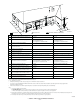
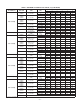
TABLE 4—ELECTRICAL DATA
UNIT
SIZE
VOLTS—
HERTZ—
PHASE
OPERATING
VOLTAGE RANGE
MAX
UNIT
AMPS
UNIT
AMPACITY†
MIN
WIRE
GAGE
MAX WIRE
LENGTH
(FT)‡
MAX FUSE
OR CKT BKR
AMPS**
Max* Min*
024040 115—60—1 127 104 6.1 8.4 14 44 15
036040 115—60—1 127 104 7.3 10.0 14 37 15
024060 115—60—1 127 104 6.1 8.4 14 44 15
036060 115—60—1 127 104 7.1 9.8 14 38 15
048060 115—60—1 127 104 9.5 12.8 14 29 15
036080 115—60—1 127 104 7.6 10.4 14 36 15
048080 115—60—1 127 104 10.0 13.4 14 28 15
060080 115—60—1 127 104 14.1 18.4 12 31 20
048100 115—60—1 127 104 10.2 13.5 14 27 15
060100 115—60—1 127 104 14.8 19.3 12 30 20
060120 115—60—1 127 104 14.6 19.1 12 30 20
060140 115—60—1 127 104 14.3 18.8 12 30 20
* Permissible limits of voltage range at which unit will operate satisfactorily.
† Unit ampacity = 125 percent of largest operating component’s full load amps plus 100 percent of all other potential operating components’ (EAC, humidifier, etc.) full load
amps.
‡ Length shown is as measured 1 way along wire path between unit and service panel for maximum 2 percent voltage drop.
** Time-delay type is recommended.
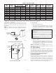
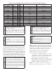
Fig. 28—Bottom Filter Arrangement
A00290
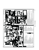
COPPER
WIRE ONLY
ELECTRIC
DISCONNECT
SWITCH
ALUMINUM
WIRE
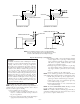
Fig. 29—Relocating J-Box
A00212
FACTORY
INSTALLED
LOCATION
ALTERNATE
FIELD
LOCATION
—21—
→