
Operating instructions


WARNING: CARBON MONOXIDE POISONING HAZARD
Failure to follow the steps outlined below for each appliance connected to the venting system being placed into operation could result
in carbon monoxide poisoning or death.
The following steps shall be followed for each appliance connected to the venting system being placed into operation, while all other
appliances connected to the venting system are not in operation:
1. Seal any unused openings in venting system.
2. Inspect the venting system for proper size and horizontal pitch, as required in the National Fuel Gas Code, ANSI Z223.1-2002/NFPA
54-2002 or the CSA B149.1, Natural Gas and Propane Installation Code and these instructions. Determine that there is no blockage
or restriction, leakage, corrosion and other deficiencies, which could cause an unsafe condition.
3. As far as practical, close all building doors and windows and all doors between the space in which the appliance(s) connected to the
venting system are located and other spaces of the building.
4. Close fireplace dampers.
5. Turn on clothes dryers and any appliance not connected to the venting system. Turn on any exhaust fans, such as range hoods and
bathroom exhausts, so they are operating at maximum speed. Do not operate a summer exhaust fan.
6. Follow the lighting instructions. Place the appliance being inspected into operation. Adjust the thermostat so appliance is operating
continuously.
7. Test for spillage from draft hood equipped appliances at the draft hood relief opening after 5 minutes of main burner operation. Use
the flame of a match or candle.
8. If improper venting is observed during any of the above tests, the venting system must be corrected in accordance with the National
Fuel Gas Code, ANSI Z223.1-2002/NFPA 54-2002 and/or CSA B149.1, Natural Gas and Propane Installation Code.
9. After it has been determined that each appliance connected to the venting system properly vents when tested as outlined above, return
doors, windows, exhaust fans, fireplace dampers and any other gas-fired appliance to their previous conditions of use.
Vent system or vent connectors may need to be resized. For any
other appliances when resizing vent systems or vent connectors,
system or connector must be sized to approach minimum size as
determined using appropriate table found in the NFGC or NSC-
NGPIC.
B. Combustion-air and Vent Piping
GENERAL
Combustion-air and vent pipe, fittings, primers, and solvents must
conform to American National Standards Institute (ANSI) stan-
dards and American Society for Testing and Materials (ASTM)
standards. See Table 6 for approved materials for use in the U.S.A.
and Canada. In Canada construct all combustion-air and vent pipes
for this unit of CSA or ULC listed schedule-40 PVC, PVC-DWV
or ABS-DWV pipe and pipe cement. SDR pipe is NOT approved
in Canada.
See Table 7 for maximum pipe lengths and Fig. 36, 37, 38, 39, and
40 for exterior piping arrangements.
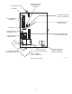
NOTE: Furnace combustion-air and vent pipe connections are
sized for 2-in. pipe. Any pipe size change should be made outside
furnace casing in vertical pipe. (See Fig. 32.) This allows proper
drainage of vent condensate.
Combustion-air and vent pipes must terminate together in same
atmospheric pressure zone, either through roof or sidewall (roof
termination preferred), using accessory termination kit.
See Table 5 for required clearances.
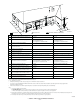
Furnace combustion-air and vent pipe connections must be at-
tached as shown in Fig. 33. Combustion-air intake plug fitting and
inducer housing alternate vent cap may need to be relocated in
some applications.
NOTE: Slope combustion-air and vent pipes a minimum of 1/4
in. per linear ft with no sags between hangers.
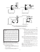
Fig. 32—Combustion-Air and Vent Pipe Diameter
Transition Location and Elbow Configuration
A93034
FURNACE
PIPE DIAMETER
TRANSITION IN
VERTICAL SECTION
NOT IN
HORIZONTAL
SECTION
Fig. 33—Combustion-Air and Vent Pipe Connections
A96187
COMBUSTION-
AIR
COMBUSTION-
AIR
AIR
FLOW
VENT
VENT
VENT
AIR
FLOW
AIR
FLOW
AIR
FLOW
UPFLOW DOWNFLOW
HORIZONTAL-LEFT DISCHARGE HORIZONTAL-RIGHT DISCHARGE
Select 1 vent pipe connection and
1 combustion-air pipe connection.
COMBUSTION-
AIR
COMBUSTION-
AIR
COMBUSTION-
AIR
COMBUSTION-
AIR
VENT
VENT
VENT
NOTE: Select 1 vent pipe connection and
1 combustion-air pipe connection.
NOTE:
—24—