
Operating instructions


3. Natural gas service pressure must not exceed 0.5 psig
(14-in. wc), but must be no less than 0.16 psig (4.5-in. wc).
4. Blower access panel must be in place to complete 115-v
electrical circuit to furnace.
CAUTION: UNIT MAY NOT OPERATE
Failure to follow this caution may result in intermittent
unit operation.
These furnaces are equipped with a manual reset limit
switch in burner box. This switch will open and shut off
power to gas control if an overheat condition (flame
rollout) occurs in burner enclosure. Correct inadequate
combustion-air supply or improper venting condition and
reset switch. DO NOT jumper this switch.
Before operating furnace, check flame rollout manual reset switch
for continuity. If necessary, press button to reset switch.
II. PRIME CONDENSATE TRAP WITH WATER
CAUTION: UNIT MAY NOT OPERATE
Failure to follow this caution may result in intermittent
unit operation.
Condensate trap must be PRIMED or proper draining
may not occur. The condensate trap has 2 internal
chambers which can ONLY be primed by pouring water
into the inducer drain side of condensate trap.
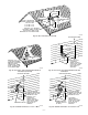
1. Remove upper inducer housing drain connection cap. (See
Fig. 48)
2. Connect field-supplied 1/2-in. ID tube to upper inducer
housing drain connection.
3. Insert field-supplied funnel into tube.
4. Pour 1 quart of water into funnel/tube. Water should run
through inducer housing, overfill condensate trap, and flow
into open field drain. (See Fig. 49.)
5. Remove funnel and tube from inducer housing and replace
drain connection cap and clamp.
Fig. 47—Condensate Trap Heat Tape
A93036
CONDENSATE TRAP
WIRE TIE(S)
HEAT TAPE
(3 WRAPS MINIMUM)
Fig. 49—Filling Condensate Trap
A99119
Fig. 48—Inducer Housing Drain Cap
A99118
—36—