
Operating instructions


c. Jumper R and W thermostat connections on control to
start furnace operation.
d. Turn adjusting screw, counterclockwise (out) to decrease
manifold pressure or clockwise (in) to increase manifold
pressure.
NOTE: This furnace has been approved for a manifold pressure
of 3.2 in. wc to 3.8 in. wc when installed at altitudes up to 2000 ft.
For altitudes above 2000 ft, the manifold pressure can be adjusted
from 2.0 in. wc to 3.8 in. wc. If manifold pressure is outside this
range, change burner orifices to obtain pressure in this range.
CAUTION: UNIT DAMAGE HAZARD
Failure to follow this caution may result in reduced
furnace life.
DO NOT bottom out gas valve regulator adjusting screw.
This will result in unregulated manifold pressure and
result in excess overfire and heat exchanger failures.
NOTE: If orifice hole appears damaged or it is suspected to have
been redrilled, check orifice hole with a numbered drill bit of
correct size. Never redrill an orifice. A burr-free and squarely
aligned orifice hole is essential for proper flame characteristics.
e. Replace gas valve regulator adjustment screw cap.
f. Replace burner enclosure front and verify adjusted gas
input rate using method outlined in item 3.
g. Look through sight glass in burner enclosure and check
burner flame. Burner flame should be clear blue, almost
transparent. (See Fig. 52.)
h. Remove jumper from R and W.
3. Verify natural gas input rate by clocking gas meter.
NOTE: Be sure all pressure tubing, combustion-air and vent
pipes, and burner enclosure front are in place when checking input
by clocking gas meter.
a. Calculate high-altitude adjustment (if required).
UNITED STATES
At altitudes above 2000 ft, this furnace has been ap-
proved for a 2% derate for each 1000 ft above sea level.
See Table 11 for derate multiplier factor.
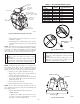
Fig. 50—Redundant Automatic Gas Valve
A03142
REGULATOR
SEAL CAP
REGULATOR
ADJUSTMENT
SCREW
REGULATOR SPRING
(PROPANE - WHITE, 6 TURNS
NATURAL - SILVER, 10 TURNS)
GAS PRESSURE
REGULATOR
ADJUSTMENT
MANIFOLD
PRESSURE TAP
INLET
PRESSURE TAP
ON/OFF SWITCH
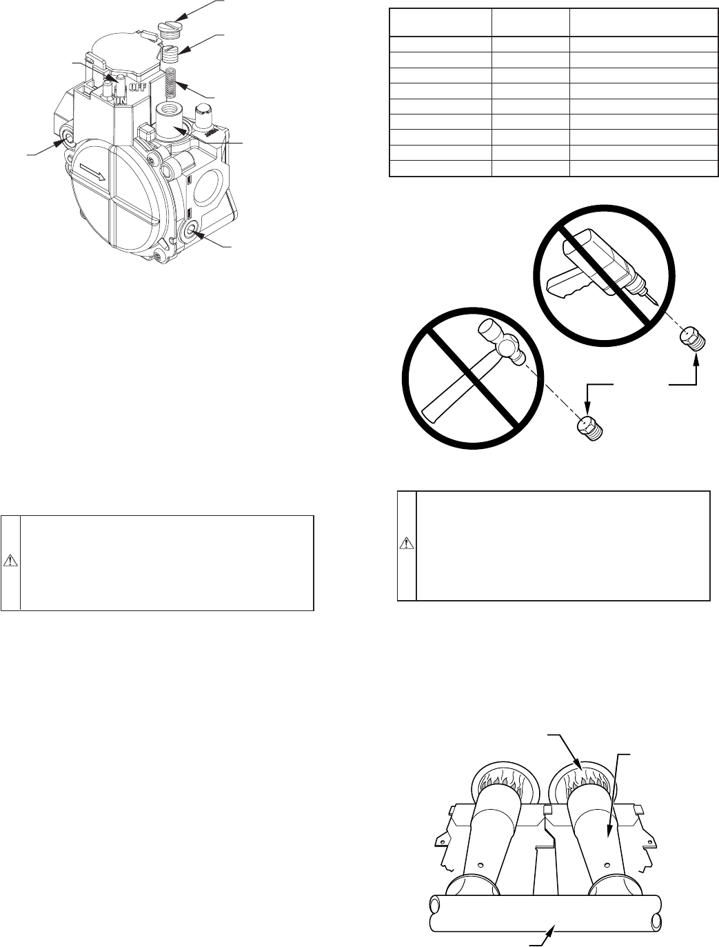
Fig. 52—Burner Flame
A89020
BURNER FLAME
BURNER
MANIFOLD
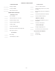
TABLE 11—ALTITUDE DERATE MULTIPLIER
ALTITUDE
(FT)
%OF
DERATE
DERATE MULTIPLIER
FACTOR FOR U.S.A.*
0—2000 0 1.00
2001—3000 4—6 0.95
3001—4000 6—8 0.93
4001—5000 8—10 0.91
5001—6000 10—12 0.89
6001—7000 12—14 0.87
7001—8000 14—16 0.85
8001—9000 16—18 0.83
9001—10,000 18—20 0.81
* Derate multiplier factor is based on midpoint altitude for altitude range.
Fig. 51—Burner Orifice
CAUTION: UNIT DAMAGE HAZARD
Failure to follow this caution may result in component
damage due to flame impingement of burners and heat
exchangers.
DO NOT redrill orifices. Improper drilling (burrs, out-of-
round holes, etc.) can cause excessive burner noise and
misdirection of burner flames. (See Fig. 51.)
A93059
BURNER
ORIFICE
—44—
→