
Operating instructions


a. Comply with all clearance requirements as stated in
Table 6.
b. Termination kit should be positioned where vent vapors
will not damage plants/shrubs or air conditioning equip-
ment.
c. Termination kit should be positioned so it will not be
affected by wind eddy (such as inside building corners)
or accumulation of airborne leaves or light snow, or
allow recirculation of flue gases.
d. Termination kit should be positioned where it will not be
damaged by or subjected to foreign objects, such as
stones, balls, etc.
e. Termination kit should be positioned where vent vapors
are not objectionable.
2. Cut one 4-in. diameter hole for 2-in. kit, or one 5-in.
diameter hole for 3-in. kit.
3. Loosely assemble concentric vent/air termination compo-
nents together using instructions in kit.
4. Slide assembled kit with rain shield REMOVED through
hole.
NOTE: Do not allow insulation or other materials to accumulate
inside of pipe assembly when installing it through hole.
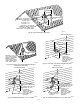
Roof terminations—Locate assembly through roof to ap-
propriate height as shown in Fig. 38.
Sidewall terminations—Locate assembly through sidewall
with rain shield positioned no more than 1-in. from wall as
shown in Fig. 38.
5. Disassemble loose pipe fittings. Clean and cement using
same procedures as used for system piping.
6. Check required dimensions as shown in Fig. 38 or 39.
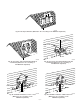
D. Multiventing and Vent Terminations
When 2 or more 355MAV Furnaces are vented near each other,
each furnace must be individually vented. NEVER common vent
or breach vent 355MAV furnaces. When 2 or more 355MAV
furnaces are vented near each other, 2 vent terminations may be
installed as shown in Fig. 42, 43, 44, 45, or 46, but next vent
termination must be at least 36 in. away from first 2 terminations.
It is important that vent terminations be made as shown to avoid
recirculation of flue gases. Dimension "A" in Fig. 42, 43, 44, 45,
and 46 represents distance between pipes or rain shields, as
touching or 2-in. maximum separation.
X. CONDENSATE DRAIN
A. General
Condensate trap is shipped installed in the blower shelf and factory
connected for UPFLOW applications. Condensate trap must be
RELOCATED for use in DOWNFLOW and HORIZONTAL
applications.
Condensate trap MUST be used for all applications.
An external trap is not required when connecting the field drain to
this condensate trap.
The field drain connection (condensate trap or drain tube coupling)
is sized for 1/2-in. CPVC, 1/2-in. PVC, or 5/8-in. ID tube
connection.
Drain pipe and fittings must conform to ANSI standards and
ASTM D1785, D2466, or D2846. CPVC or PVC cement must
conform to ASTM D2564 or F493. Primer must conform to ASTM
F656. In Canada, use CSA or ULC certified schedule 40 CPVC or
PVC drain pipe, fittings, and cement.
When a condensate pump is required, select a pump which is
approved for condensing furnace applications. To avoid conden-
sate spillage, select a pump with an overflow switch.
Furnace condensate is mildly acidic, typically in the pH range of
3.2 to 4.5. Due to corrosive nature of this condensate, a condensate
pH neutralizing filter may be desired. Check with local authorities
to determine if a pH neutralizer is required.
B. Application
The furnace, A/C, and humidifier drains may be combined and
drained together. The A/C drain must have an external, field-
supplied trap prior to the furnace drain connection. All drain
connections (furnace, A/C, or humidifier) must be terminated into
an open or vented drain as close to the respective equipment as
possible to prevent siphoning of the equipment’s drain.
See Fig. 48 for example of possible field drain attachment using
1/2-in. CPVC or PVC tee for vent and A/C or humidifier drain
connection.
Outdoor draining of the furnace is permissible if allowed by local
codes. Caution should be taken when freezing ambient may freeze
drain pipe and prohibit draining.
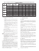
TABLE 8—MAXIMUM ALLOWABLE EXPOSED VENT PIPE LENGTH (FT) WITH INSULATION IN WINTER DESIGN
TEMPERATURE AMBIENT*
UNIT
SIZE
WINTER DESIGN
TEMPERATURE
(°F)
MAXIMUM PIPE
DIAMETER
(IN.)
INSULATION THICKNESS (IN.)†
0 3/8 1/2 3/4 1
042040
20 2 2137425057
0 2 10 22 25 30 35
-20 2 5 14 17 21 25
042060
20 2 3055617070
0 2 16 33 38 46 53
-20 2 9 23 26 33 38
042080
060080
20 2 3765707070
0 2 20 39 45 55 63
-20 2 1127313945
060100
20 2-1/2 41 70 70 70 70
0 2-1/2 21 42 48 59 68
-20 2-1/2 11 28 33 41 49
060120
20 3 4970707070
0 3 26 51 58 70 70
-20 3 1535405059
* Pipe length (ft) specified for maximum pipe lengths located in unconditioned spaces. Pipes located in unconditioned space cannot exceed total allowable pipe length as
specified in Table 7.
† Insulation thickness based on R value of 3.5 per in.
—34—