
Operating instructions


e. Turn low-heat adjusting screw (3/32 hex Allen wrench)
counterclockwise (out) to decrease input rate or clock-
wise (in) to increase input rate.
NOTE: DO NOT set low-heat manifold pressure less than 1.3-in.
wc or more than 1.7-in. wc for natural gas. If manifold pressure is
outside this range, change main burner orifices to obtain manifold
pressure in this range.
CAUTION: UNIT DAMAGE HAZARD
Failure to follow this caution may result in reduced
furnace life.
DO NOT bottom-out gas valve regulator adjusting screw.
This can result in unregulated manifold pressure and
result in excess overfire and heat exchanger failures.
NOTE: If orifice hole appears damaged or it is suspected to have
been redrilled, check orifice hole with a numbered drill bit of
correct size. Never redrill an orifice. A burr-free and squarely
aligned orifice hole is essential for proper flame characteristics.
f. Turn setup switch SW1-2 to OFF position after complet-
ing low-heat adjustment.
g. Jumper R and W/W1 and W2 thermostat connections on
furnace control. (See Fig. 32.) This keeps furnace locked
in high-heat operation.
h. Turn high-heat adjusting screw (3/32 hex Allen wrench)
counterclockwise (out) to decrease input rate or clock-
wise (in) to increase rate.
NOTE: DO NOT set high-heat manifold pressure less than 3.2-in.
wc or more than 3.8-in. wc for natural gas. If manifold pressure is
outside this range, change main burner orifices to obtain manifold
pressures in this range.
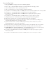
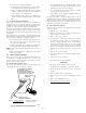
i. When correct input is obtained, replace caps that conceal
gas valve regulator adjustment screws. Main burner
flame should be clear blue, almost transparent. (See Fig.
64.)
j. Remove jumpers R-to-W/W1 and R-to-W2.
3. Verify natural gas input rate by clocking gas meter.
NOTE: Be sure all pressure tubing, combustion-air and vent
pipes, and burner enclosure front are in place when checking input
by clocking gas meter.
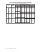
a. Calculate high-altitude adjustment (if required).
UNITED STATES
At altitudes above 2000 ft, this furnace has been ap-
proved for a 2 percent derate for each 1000 ft above sea
level. See Table 12 for derate multiplier factor and
example.
EXAMPLE: 100,000 BTUH HIGH-HEAT INPUT FURNACE IN-
STALLED AT 4300 FT.
Furnace Input Rate
at Sea Level
X
Derate
Multiplier
Factor
=
Furnace Input Rate
at Installation
Altitude
100,000 X 0.91 = 91,000
CANADA
At installation altitudes from 2000 to 4500 ft, this
furnace must be derated 5 percent by an authorized Gas
Conversion Station or Dealer. To determine correct input
rate for altitude, see example above and use 0.95 as
derate multiplier factor.
b. Reinstall burner box cover.
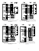
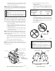
Fig. 62—Redundant Automatic Gas Valve
A04048
REGULATOR COVER SCREW
PLASTIC ADJUST SCREW
LOW STAGE
GAS PRESSURE
REGULATOR ADJUSTMENT
(
PROPANE–WHITE, 9.5 TURNS
NATURAL–SILVER,9.5 TURNS)
MANIFOLD
PRESSURE TAP
INLET
PRESSURE TAP
ON/OFF SWITCH
REGULATOR SPRING
HIGH STAGE GAS
PRESSURE REGULATOR
ADJUSTMENT
(
PROPANE–WHITE, 13.5 TURNS
NATURAL–SILVER,12 TURNS)
CAUTION: UNIT DAMAGE HAZARD
Failure to follow this caution may result in component
damage due to flame impingement of burners and heat
exchangers.
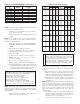
DO NOT redrill orifices. Improper drilling (burrs, out-of-
round holes, etc.) can cause excessive burner noise and
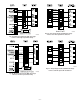
misdirection of burner flames. (See Fig. 63.)
A93059
Fig. 63—Burner Orifice
BURNER
ORIFICE
Fig. 64—Burner Flame
A89020
BURNER FLAME
BURNER
MANIFOLD
—47—
→